EP0880042A2 - A method of and a device for making bragg gratings in optical fibres or waveguides - Google Patents
A method of and a device for making bragg gratings in optical fibres or waveguides Download PDFInfo
- Publication number
- EP0880042A2 EP0880042A2 EP98108857A EP98108857A EP0880042A2 EP 0880042 A2 EP0880042 A2 EP 0880042A2 EP 98108857 A EP98108857 A EP 98108857A EP 98108857 A EP98108857 A EP 98108857A EP 0880042 A2 EP0880042 A2 EP 0880042A2
- Authority
- EP
- European Patent Office
- Prior art keywords
- waveguides
- radiation
- reciprocation
- fibres
- refractive index
- Prior art date
- Legal status (The legal status is an assumption and is not a legal conclusion. Google has not performed a legal analysis and makes no representation as to the accuracy of the status listed.)
- Granted
Links
- 230000003287 optical effect Effects 0.000 title claims abstract description 20
- 238000000034 method Methods 0.000 title claims abstract description 15
- 230000005855 radiation Effects 0.000 claims abstract description 31
- 238000009826 distribution Methods 0.000 claims abstract description 7
- 238000004519 manufacturing process Methods 0.000 claims abstract description 5
- 230000008859 change Effects 0.000 claims abstract description 4
- 230000000737 periodic effect Effects 0.000 claims description 6
- 239000007787 solid Substances 0.000 claims 1
- 239000000835 fiber Substances 0.000 abstract description 16
- 230000008878 coupling Effects 0.000 description 5
- 238000010168 coupling process Methods 0.000 description 5
- 238000005859 coupling reaction Methods 0.000 description 5
- 239000013307 optical fiber Substances 0.000 description 3
- 230000008569 process Effects 0.000 description 3
- 238000005286 illumination Methods 0.000 description 2
- 230000004044 response Effects 0.000 description 2
- 230000003595 spectral effect Effects 0.000 description 2
- 206010034972 Photosensitivity reaction Diseases 0.000 description 1
- VYPSYNLAJGMNEJ-UHFFFAOYSA-N Silicium dioxide Chemical class O=[Si]=O VYPSYNLAJGMNEJ-UHFFFAOYSA-N 0.000 description 1
- 230000005540 biological transmission Effects 0.000 description 1
- 238000005352 clarification Methods 0.000 description 1
- 230000001419 dependent effect Effects 0.000 description 1
- 230000000694 effects Effects 0.000 description 1
- 238000005516 engineering process Methods 0.000 description 1
- 238000000605 extraction Methods 0.000 description 1
- 229910052732 germanium Inorganic materials 0.000 description 1
- GNPVGFCGXDBREM-UHFFFAOYSA-N germanium atom Chemical compound [Ge] GNPVGFCGXDBREM-UHFFFAOYSA-N 0.000 description 1
- 238000001093 holography Methods 0.000 description 1
- 238000009776 industrial production Methods 0.000 description 1
- 230000010354 integration Effects 0.000 description 1
- 230000001678 irradiating effect Effects 0.000 description 1
- 238000012986 modification Methods 0.000 description 1
- 230000004048 modification Effects 0.000 description 1
- 230000036211 photosensitivity Effects 0.000 description 1
Images
Classifications
-
- G—PHYSICS
- G02—OPTICS
- G02B—OPTICAL ELEMENTS, SYSTEMS OR APPARATUS
- G02B6/00—Light guides; Structural details of arrangements comprising light guides and other optical elements, e.g. couplings
- G02B6/02—Optical fibres with cladding with or without a coating
- G02B6/02057—Optical fibres with cladding with or without a coating comprising gratings
- G02B6/02076—Refractive index modulation gratings, e.g. Bragg gratings
- G02B6/02123—Refractive index modulation gratings, e.g. Bragg gratings characterised by the method of manufacture of the grating
- G02B6/02133—Refractive index modulation gratings, e.g. Bragg gratings characterised by the method of manufacture of the grating using beam interference
- G02B6/02138—Refractive index modulation gratings, e.g. Bragg gratings characterised by the method of manufacture of the grating using beam interference based on illuminating a phase mask
-
- G—PHYSICS
- G02—OPTICS
- G02B—OPTICAL ELEMENTS, SYSTEMS OR APPARATUS
- G02B6/00—Light guides; Structural details of arrangements comprising light guides and other optical elements, e.g. couplings
- G02B6/02—Optical fibres with cladding with or without a coating
- G02B6/02057—Optical fibres with cladding with or without a coating comprising gratings
- G02B6/02076—Refractive index modulation gratings, e.g. Bragg gratings
- G02B6/02123—Refractive index modulation gratings, e.g. Bragg gratings characterised by the method of manufacture of the grating
- G02B6/02152—Refractive index modulation gratings, e.g. Bragg gratings characterised by the method of manufacture of the grating involving moving the fibre or a manufacturing element, stretching of the fibre
Definitions
- This invention relates to the fabrication of optical fibre components for optical telecommunications, and more specifically its object is to provide a method of and a device for making identical Bragg gratings in separate photosensitive optical fibres or waveguides.
- wavelength selective optical components that are based on Bragg gratings made in an optical fibre or planar waveguide and that exploit the fact that a Bragg grating with a given pitch reflects a certain wavelength and transmits the other wavelengths.
- Said gratings are made of spans of fibre or waveguide that show periodic refractive index changes along their length.
- a commonly used technique for obtaining these periodic refractive index changes is to illuminate the fibre or the waveguide with an interference fringe pattern obtained through holography or through direct interference between two UV beams or by means of a mask on which a grating has been made which spatially modulates a characteristic of the radiation sent to the fibre or waveguide, e. g. its phase.
- an optical waveguide coupler is formed by two portions of fibre or guide, which are joined in their middle part (coupling region), as depicted in Figure 1.
- a grating is made in each of the two fibre or waveguide portions (in the region where they are separate), so that the radiation at the wavelength of interest, sent through a coupler branch (for instance, branch 100A), is reflected by both gratings and goes out through one of the other branches, at the same end from which it has been launched (e. g. through branch 101B).
- branch 100A a coupler branch
- branch 101B a coupler branch
- a non-negligible percentage of such a radiation is reflected towards the input branch, causing disturbances.
- substantially identical means here that the spectral response curves must coincide to an extent greater than 90 % in the band of interest, in order to keep the unwanted reflection below 10 %.
- a different approach is to irradiate the fibres or waveguides by means of a beam that has such a width as to illuminate the cores of all fibres or waveguides. In this case, too, it appears rather difficult to ensure a uniform illumination of all fibres or waveguides by the beam. Besides, the process time becomes longer, and work bench vibrations might occur, which would affect the overall quality.
- the present invention alms to provide a method and a device which allow such uniform illumination of all fibres or guides involved in grating writing.
- the invention concerns a method wherein the optical fibres or waveguides are exposed, for a portion of their lengths, to a radiation whose intensity distribution is such as to cause periodic refractive index changes in the irradiated fibre or waveguide portion and wherein, for making identical gratings on multiple fibres or waveguides, such fibres or waveguides are located side-by-side and are jointly subjected to a reciprocation transversally to their longitudinal axis, at such a low frequency that, at each pass under the radiation, each fibre or waveguide is exposed to the radiation for a time sufficient to ensure an adequate change in their refractive index.
- the present invention also concerns a device for carrying out the process, wherein a source sends towards the fibres or waveguides, through an optical system, a radiation which at its incidence onto the fibres or waveguides shows an intensity distribution such as to originate periodic refractive index changes in the irradiated zone, and wherein, to make identical gratings on multiple fibres or waveguides, these are mounted side-by-side on a common support, associated to means for causing its reciprocation transversally to the longitudinal axis of the waveguides, at such a low frequency that, at each pass under the radiation, each waveguide remains exposed to the radiation for a time sufficient to ensure the refractive index change.
- GB-A 2283831 discloses a coupler in which gratings are made in a zone located downstream of the coupling region and states that such gratings are simultaneously written and are substantially identical or form a single grating. Nevertheless, no information is provided about the way such identity is guaranteed.
- a coupler in fibre or waveguide that can be used in grating devices, such as band pass filters or add-drop multiplexers, is formed by two portions of optical fibre or waveguide, which are joined in the central part and form the four branches 100A, 100B, 101A, 101B of the coupler.
- the central part 102 forms the coupling region.
- Both fibres or waveguides have a grating 103, 104, located downstream of coupling region 102, so that the radiation at the wavelength of interest, sent through a coupler branch (e. g. branch 100A), is reflected by both gratings 103, 104 and goes out through one of the other branches (in Figure, branch 101B), on the same side where it has been launched.
- Both gratings must be substantially identical (i. e. must have spectral response curves which, in the band of interest, coincide by more than 90 %) in order to minimise the percentage of incident radiation which is reflected towards input branch 100A, causing disturbances.
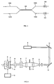
- FIG. 2 a device suitable for fabricating identical gratings on a group of fibres 1 is depicted.
- Fibres 1 are mounted in a support 2, which also carries a phase mask 3. This support must guarantee that the position of fibres 1 relative to phase mask 3 remains constant with time.
- phase mask 3 is illuminated by the UV radiation emitted by a laser 4, through an optical system capable of creating onto the phase mask an image of the source formed by a thin strip of the same length as the grating to be fabricated.
- the optical system includes, in known manner, a first lens 5 to expand the beam emitted by the source; a group of lenses 6, 7, 8 to generate a collimated beam; a diaphragm 9 between lenses 6, 7 to shape the beam, giving it for instance a Gaussian intensity distribution; a cylindrical lens 10 to form the source image on phase mask 3.
- the radiation emitted by source 4 is sent towards the optical system through a pair of mirrors 11, 12, which allow obtaining, between source 4 and phase mask 3, a sufficiently long path to make the secondary mode effect negligible and at the same time allow keeping the device to a small size.
- support 2 is mounted on a guide (not depicted), perpendicular to the longitudinal axis of the fibres, along which guide said support can be reciprocated, for instance under the control of a motor 13, so as to cause the UV radiation to scan the fibres. Scanning of the fibres determines that at each pass under the radiation said fibres substantially receive the same beam, thus obtaining the actual identity of the gratings being fabricated and avoiding problems due for instance to an alignment between fibres 1 and optical system 5 - 10 which might be not completely accurate.
- laser 4 be a continuous wave laser; also a pulsed laser can be used, such an excimer laser, but it must show a high pulse repetition rate, e. g. a rate higher than one hundred Hz (e. g. 100 - 150 Hz).
- the frequency of the reciprocation and the overall duration of irradiation are dependent on the source power, on the photosensitivy characteristics of the fibres as well as on the number of fibres into which the gratings are to be written.
- such frequency shall have to be sufficiently low as to guarantee that each fibre, at each step, remains exposed for a sufficient time such as to ensure the start of the refractive index variation: thanks to the repeated passages of each fibre before the irradiating beam, an integration in time is then obtained of the irradiated power so that at the process end the refractive index differences actually needed for a grating are obtained.
Landscapes
- Physics & Mathematics (AREA)
- Engineering & Computer Science (AREA)
- Manufacturing & Machinery (AREA)
- General Physics & Mathematics (AREA)
- Optics & Photonics (AREA)
- Diffracting Gratings Or Hologram Optical Elements (AREA)
- Optical Fibers, Optical Fiber Cores, And Optical Fiber Bundles (AREA)
- Optical Integrated Circuits (AREA)
- Glass Compositions (AREA)
Abstract
Description
- Figure 1 shows an optical coupler with gratings; and
- Figure 2 shows a device for carrying out the method according to this invention.
Claims (12)
- Method of making Bragg gratings in single mode optical waveguides (1), in which the waveguides (1) are exposed for a portion of their length to the action of a radiation with an intensity distribution such as to cause periodic refractive index changes along the irradiated zone, characterised in that, for making identical gratings on multiple waveguides (1), said waveguides (1) are located side-by-side and are jointly subjected to a reciprocation transversal to their longitudinal axis, at such a low frequency that, at each pass under the radiation, each waveguide remains exposed to the radiation for a time sufficient to start the refractive index variation.
- Method as claimed in claim 1, in which said radiation is sent onto the waveguides (1) by means of a phase mask (3), characterised in that said mask (3) is subjected to the reciprocation jointly with the waveguides (1).
- Method as claimed in claim 1 or 2, characterised in that such reciprocation has a frequency of the order of 1 Hz or less.
- Method as claimed in any of claims 1 to 3, characterised in that said radiation is a continuous radiation.
- Method as claimed in any of claims 1 to 3, characterised in that such a radiation is a pulsed radiation with a pulse repetition rate much higher than the frequency of the reciprocation.
- Method as claimed in claim 5, characterised in that the pulse repetition rate is at least 100 Hz.
- Device for making Bragg gratings in optical waveguides, in which a source (4) sends towards the waveguides (1) through an optical system (5 - 10) a radiation which at its incidence on the waveguides (1) has an intensity distribution such as to cause periodic refractive index changes in the irradiated zone, characterised in that, to make identical gratings on multiple waveguides (1), said waveguides are mounted side-by-side on a common support (2) associated with means (13) to impart it a reciprocation transversal to the longitudinal axis of the waveguides (1), at such a low frequency that, at each pass under the radiation, each waveguide remains exposed to the radiation for a sufficient time so as to start the refractive index change.
- Device as claimed in claim 7, characterised in that said support (2) also carries a phase mask (3), solid with the waveguides (1).
- Device as claimed in claim 7 or 8, characterised in that the means (13) for causing the reciprocation of said support (2) are arranged to induce a motion at a frequency of the order of 1 Hz or less.
- Device as claimed in any of claims 7 to 9, characterised in that the source (4) is a continuous wave source.
- Device as claimed in any of claims 7 to 9, characterised in that source (4) is a pulsed source, with a pulse repetition rate much higher than the frequency of the reciprocation.
- Device as claimed in claim 11, characterised in that the pulse repetition rate is at least 100 Hz.
Applications Claiming Priority (2)
| Application Number | Priority Date | Filing Date | Title |
|---|---|---|---|
| IT97TO000424A IT1292316B1 (en) | 1997-05-20 | 1997-05-20 | PROCEDURE AND DEVICE FOR THE CREATION OF FIBER BRAGG GRATINGS OR OPTICAL WAVE GUIDES. |
| ITTO970424 | 1997-05-20 |
Publications (3)
| Publication Number | Publication Date |
|---|---|
| EP0880042A2 true EP0880042A2 (en) | 1998-11-25 |
| EP0880042A3 EP0880042A3 (en) | 1999-02-24 |
| EP0880042B1 EP0880042B1 (en) | 2004-10-20 |
Family
ID=11415715
Family Applications (1)
| Application Number | Title | Priority Date | Filing Date |
|---|---|---|---|
| EP98108857A Expired - Lifetime EP0880042B1 (en) | 1997-05-20 | 1998-05-15 | A method of and a device for making bragg gratings in optical fibres or waveguides |
Country Status (6)
| Country | Link |
|---|---|
| US (1) | US5953472A (en) |
| EP (1) | EP0880042B1 (en) |
| JP (1) | JP2920762B2 (en) |
| CA (1) | CA2237963C (en) |
| DE (2) | DE880042T1 (en) |
| IT (1) | IT1292316B1 (en) |
Cited By (2)
| Publication number | Priority date | Publication date | Assignee | Title |
|---|---|---|---|---|
| EP1014124A2 (en) * | 1998-12-21 | 2000-06-28 | OTC Optical Technologies Center | Method of and device for optical fibre grating fabrication |
| EP1067411A1 (en) * | 1999-07-07 | 2001-01-10 | Samsung Electronics Co., Ltd. | Apparatus and nethod for fabricating fiber grating |
Families Citing this family (10)
| Publication number | Priority date | Publication date | Assignee | Title |
|---|---|---|---|---|
| JP2002529762A (en) * | 1998-10-30 | 2002-09-10 | コーニング インコーポレイテッド | Wavelength tuning of light-induced diffraction grating |
| US6249624B1 (en) * | 1998-12-04 | 2001-06-19 | Cidra Corporation | Method and apparatus for forming a Bragg grating with high intensity light |
| JP2000249819A (en) * | 1999-02-26 | 2000-09-14 | Mitsubishi Electric Corp | Method and device for production of grating |
| KR100334812B1 (en) | 1999-07-02 | 2002-05-02 | 윤종용 | Apodized fiber grating fabricating system |
| JP2003510854A (en) * | 1999-09-29 | 2003-03-18 | コーニング オーティーイー エッセピーアー | Fiber laser manufacturing method |
| KR100315671B1 (en) * | 1999-12-28 | 2001-11-29 | 윤종용 | Apparatus and method for fabricating multi-period optical fiber grating |
| US6522808B1 (en) * | 2000-01-15 | 2003-02-18 | Corning Incorporated | System and method for writing fiber gratings and other components |
| KR100342493B1 (en) * | 2000-07-25 | 2002-06-28 | 윤종용 | Optical fiber grating fabricating apparatus for minimizing diffraction effect |
| US6603559B2 (en) * | 2001-10-11 | 2003-08-05 | Yuan Ze University | Silicon-on-insulator optical waveguide Michelson interferometer sensor for temperature monitoring |
| DE102009005972B4 (en) | 2009-01-23 | 2011-06-16 | Laser-Laboratorium Göttingen eV | Method for generating a periodic pattern |
Citations (5)
| Publication number | Priority date | Publication date | Assignee | Title |
|---|---|---|---|---|
| US4725110A (en) * | 1984-08-13 | 1988-02-16 | United Technologies Corporation | Method for impressing gratings within fiber optics |
| EP0606726A2 (en) * | 1993-01-14 | 1994-07-20 | AT&T Corp. | Method for forming a bragg grating in an optical medium |
| WO1995012136A1 (en) * | 1993-10-29 | 1995-05-04 | Rutgers University | Coupler device used to fabricate add-drop devices |
| GB2283831A (en) * | 1993-11-10 | 1995-05-17 | Northern Telecom Ltd | 2 x 2 single mode tapered fused optical fibre coupler bearing gratings |
| EP0762158A1 (en) * | 1995-08-16 | 1997-03-12 | AT&T Corp. | Formation of gratings in polymer-coated optical fibers |
Family Cites Families (3)
| Publication number | Priority date | Publication date | Assignee | Title |
|---|---|---|---|---|
| US5093876A (en) * | 1990-07-27 | 1992-03-03 | At&T Bell Laboratories | WDM systems incorporating adiabatic reflection filters |
| GB2297656A (en) * | 1995-02-01 | 1996-08-07 | Northern Telecom Ltd | Optical filtering |
| GB2308252B (en) * | 1995-12-16 | 2000-02-23 | Northern Telecom Ltd | WDM channel insertion |
-
1997
- 1997-05-20 IT IT97TO000424A patent/IT1292316B1/en active IP Right Grant
-
1998
- 1998-04-27 US US09/067,515 patent/US5953472A/en not_active Expired - Lifetime
- 1998-05-15 JP JP10150777A patent/JP2920762B2/en not_active Expired - Fee Related
- 1998-05-15 DE DE0880042T patent/DE880042T1/en active Pending
- 1998-05-15 DE DE69827070T patent/DE69827070T2/en not_active Expired - Fee Related
- 1998-05-15 EP EP98108857A patent/EP0880042B1/en not_active Expired - Lifetime
- 1998-05-19 CA CA002237963A patent/CA2237963C/en not_active Expired - Fee Related
Patent Citations (5)
| Publication number | Priority date | Publication date | Assignee | Title |
|---|---|---|---|---|
| US4725110A (en) * | 1984-08-13 | 1988-02-16 | United Technologies Corporation | Method for impressing gratings within fiber optics |
| EP0606726A2 (en) * | 1993-01-14 | 1994-07-20 | AT&T Corp. | Method for forming a bragg grating in an optical medium |
| WO1995012136A1 (en) * | 1993-10-29 | 1995-05-04 | Rutgers University | Coupler device used to fabricate add-drop devices |
| GB2283831A (en) * | 1993-11-10 | 1995-05-17 | Northern Telecom Ltd | 2 x 2 single mode tapered fused optical fibre coupler bearing gratings |
| EP0762158A1 (en) * | 1995-08-16 | 1997-03-12 | AT&T Corp. | Formation of gratings in polymer-coated optical fibers |
Non-Patent Citations (1)
| Title |
|---|
| F. BILODEAU et al. "High- -Return-Loss Narrowband All-Fiber Bandpass Bragg Transmission Filter", IEEE Photonics Technology Letters, January 1994, Vol. 6, No. 1, pages 80-82, XP002900207 * |
Cited By (4)
| Publication number | Priority date | Publication date | Assignee | Title |
|---|---|---|---|---|
| EP1014124A2 (en) * | 1998-12-21 | 2000-06-28 | OTC Optical Technologies Center | Method of and device for optical fibre grating fabrication |
| EP1014124A3 (en) * | 1998-12-21 | 2000-10-18 | OTC Optical Technologies Center | Method of and device for optical fibre grating fabrication |
| EP1067411A1 (en) * | 1999-07-07 | 2001-01-10 | Samsung Electronics Co., Ltd. | Apparatus and nethod for fabricating fiber grating |
| US6529658B1 (en) | 1999-07-07 | 2003-03-04 | Samsung Electronics Co., Ltd. | Apparatus and method for fabricating fiber grating |
Also Published As
| Publication number | Publication date |
|---|---|
| DE880042T1 (en) | 1999-07-22 |
| CA2237963C (en) | 2002-07-09 |
| ITTO970424A0 (en) | 1997-05-20 |
| JP2920762B2 (en) | 1999-07-19 |
| JPH10319255A (en) | 1998-12-04 |
| US5953472A (en) | 1999-09-14 |
| DE69827070T2 (en) | 2006-03-09 |
| IT1292316B1 (en) | 1999-01-29 |
| ITTO970424A1 (en) | 1998-11-20 |
| EP0880042A3 (en) | 1999-02-24 |
| DE69827070D1 (en) | 2004-11-25 |
| EP0880042B1 (en) | 2004-10-20 |
| CA2237963A1 (en) | 1998-11-20 |
Similar Documents
| Publication | Publication Date | Title |
|---|---|---|
| CA2307189C (en) | Fabrication of optical waveguide gratings | |
| US5604829A (en) | Optical waveguide with diffraction grating and method of forming the same | |
| KR100425568B1 (en) | Grating | |
| CA2195259C (en) | Optical signal shaping device for complex spectral shaping applications | |
| EP1197771A1 (en) | Method of producing a Bragg grating in an optical waveguide | |
| US20010051020A1 (en) | Formation of a refractive index grating | |
| CA2211834A1 (en) | Broadband grating | |
| CA2652823A1 (en) | Optical devices and digital laser method for writing waveguides, gratings, and integrated optical circuits | |
| EP0880042B1 (en) | A method of and a device for making bragg gratings in optical fibres or waveguides | |
| EP0881515B1 (en) | Spatial filter for high power laser beam | |
| AU763596B2 (en) | Apparatus for manufacturing long-period fiber gratings and apparatus for manufacturing two-band long-period fiber gratings using the same | |
| CN212872967U (en) | Apodization long period optical fiber grating inscribing device | |
| JP2934238B2 (en) | Jig for manufacturing long-period grating filter, apparatus and method for manufacturing long-period grating filter using the same | |
| US6591039B2 (en) | Method and equipment for writing a Bragg grating in a waveguide | |
| JP2001033612A (en) | Apodized optical fiber grating producing device | |
| US6553163B2 (en) | Method and apparatus for writing a Bragg grating in a waveguide | |
| US20020076131A1 (en) | Method and apparatus for frequency tuning of an unbalanced Mach-Zehnder interferometer | |
| KR20010028469A (en) | Apparatus for fabricating long-period optical fiber grating | |
| JP4034041B2 (en) | Manufacturing method of optical waveguide grating | |
| EP1207410A1 (en) | Method and equipment for writing a bragg grating in a waveguide | |
| JP2003232942A (en) | Method and device of manufacturing optical waveguide type diffraction grating element, optical waveguide type diffraction grating element, optical component and optical communication system | |
| KR100267516B1 (en) | Method and apparatus for manufacturing rejection filters using amplitude masks | |
| JP2001141943A (en) | Method for forming grating | |
| AU678892B2 (en) | Optical grating | |
| JPH1062636A (en) | Method of forming bragg diffraction grating |
Legal Events
| Date | Code | Title | Description |
|---|---|---|---|
| PUAI | Public reference made under article 153(3) epc to a published international application that has entered the european phase |
Free format text: ORIGINAL CODE: 0009012 |
|
| AK | Designated contracting states |
Kind code of ref document: A2 Designated state(s): CH DE FR GB IT LI NL SE |
|
| AX | Request for extension of the european patent |
Free format text: AL;LT;LV;MK;RO;SI |
|
| PUAL | Search report despatched |
Free format text: ORIGINAL CODE: 0009013 |
|
| RHK1 | Main classification (correction) |
Ipc: G02B 6/34 |
|
| AK | Designated contracting states |
Kind code of ref document: A3 Designated state(s): AT BE CH CY DE DK ES FI FR GB GR IE IT LI LU MC NL PT SE |
|
| AX | Request for extension of the european patent |
Free format text: AL;LT;LV;MK;RO;SI |
|
| EL | Fr: translation of claims filed | ||
| 17P | Request for examination filed |
Effective date: 19990322 |
|
| DET | De: translation of patent claims | ||
| TCNL | Nl: translation of patent claims filed | ||
| AKX | Designation fees paid |
Free format text: CH DE FR GB IT LI NL SE |
|
| RAP1 | Party data changed (applicant data changed or rights of an application transferred) |
Owner name: OTC OPTICAL TECHNOLOGIES CENTER S.R.L. |
|
| RAP1 | Party data changed (applicant data changed or rights of an application transferred) |
Owner name: AGILENT TECHNOLOGIES INC |
|
| RAP1 | Party data changed (applicant data changed or rights of an application transferred) |
Owner name: AGILENT TECHNOLOGIES INC. |
|
| RAP1 | Party data changed (applicant data changed or rights of an application transferred) |
Owner name: AGILENT TECHNOLOGIES INC. A DELAWARE CORPORATION |
|
| RAP1 | Party data changed (applicant data changed or rights of an application transferred) |
Owner name: AGILENT TECHNOLOGIES, INC. (A DELAWARE CORPORATION |
|
| GRAP | Despatch of communication of intention to grant a patent |
Free format text: ORIGINAL CODE: EPIDOSNIGR1 |
|
| RIC1 | Information provided on ipc code assigned before grant |
Ipc: 7G 02B 6/293 B Ipc: 7G 02B 6/124 B Ipc: 7G 02B 6/34 A |
|
| GRAS | Grant fee paid |
Free format text: ORIGINAL CODE: EPIDOSNIGR3 |
|
| GRAA | (expected) grant |
Free format text: ORIGINAL CODE: 0009210 |
|
| AK | Designated contracting states |
Kind code of ref document: B1 Designated state(s): CH DE FR GB IT LI NL SE |
|
| PG25 | Lapsed in a contracting state [announced via postgrant information from national office to epo] |
Ref country code: NL Free format text: LAPSE BECAUSE OF FAILURE TO SUBMIT A TRANSLATION OF THE DESCRIPTION OR TO PAY THE FEE WITHIN THE PRESCRIBED TIME-LIMIT Effective date: 20041020 Ref country code: LI Free format text: LAPSE BECAUSE OF FAILURE TO SUBMIT A TRANSLATION OF THE DESCRIPTION OR TO PAY THE FEE WITHIN THE PRESCRIBED TIME-LIMIT Effective date: 20041020 Ref country code: IT Free format text: LAPSE BECAUSE OF FAILURE TO SUBMIT A TRANSLATION OF THE DESCRIPTION OR TO PAY THE FEE WITHIN THE PRE;WARNING: LAPSES OF ITALIAN PATENTS WITH EFFECTIVE DATE BEFORE 2007 MAY HAVE OCCURRED AT ANY TIME BEFORE 2007. THE CORRECT EFFECTIVE DATE MAY BE DIFFERENT FROM THE ONE RECORDED.SCRIBED TIME-LIMIT Effective date: 20041020 Ref country code: FR Free format text: LAPSE BECAUSE OF FAILURE TO SUBMIT A TRANSLATION OF THE DESCRIPTION OR TO PAY THE FEE WITHIN THE PRESCRIBED TIME-LIMIT Effective date: 20041020 Ref country code: CH Free format text: LAPSE BECAUSE OF FAILURE TO SUBMIT A TRANSLATION OF THE DESCRIPTION OR TO PAY THE FEE WITHIN THE PRESCRIBED TIME-LIMIT Effective date: 20041020 |
|
| REG | Reference to a national code |
Ref country code: GB Ref legal event code: FG4D |
|
| REG | Reference to a national code |
Ref country code: CH Ref legal event code: EP |
|
| REF | Corresponds to: |
Ref document number: 69827070 Country of ref document: DE Date of ref document: 20041125 Kind code of ref document: P |
|
| PG25 | Lapsed in a contracting state [announced via postgrant information from national office to epo] |
Ref country code: SE Free format text: LAPSE BECAUSE OF FAILURE TO SUBMIT A TRANSLATION OF THE DESCRIPTION OR TO PAY THE FEE WITHIN THE PRESCRIBED TIME-LIMIT Effective date: 20050120 |
|
| REG | Reference to a national code |
Ref country code: CH Ref legal event code: PL |
|
| NLV1 | Nl: lapsed or annulled due to failure to fulfill the requirements of art. 29p and 29m of the patents act | ||
| PLBE | No opposition filed within time limit |
Free format text: ORIGINAL CODE: 0009261 |
|
| STAA | Information on the status of an ep patent application or granted ep patent |
Free format text: STATUS: NO OPPOSITION FILED WITHIN TIME LIMIT |
|
| 26N | No opposition filed |
Effective date: 20050721 |
|
| EN | Fr: translation not filed | ||
| PGFP | Annual fee paid to national office [announced via postgrant information from national office to epo] |
Ref country code: GB Payment date: 20060525 Year of fee payment: 9 |
|
| GBPC | Gb: european patent ceased through non-payment of renewal fee |
Effective date: 20070515 |
|
| PG25 | Lapsed in a contracting state [announced via postgrant information from national office to epo] |
Ref country code: GB Free format text: LAPSE BECAUSE OF NON-PAYMENT OF DUE FEES Effective date: 20070515 |
|
| PGFP | Annual fee paid to national office [announced via postgrant information from national office to epo] |
Ref country code: DE Payment date: 20081128 Year of fee payment: 11 |
|
| PG25 | Lapsed in a contracting state [announced via postgrant information from national office to epo] |
Ref country code: DE Free format text: LAPSE BECAUSE OF NON-PAYMENT OF DUE FEES Effective date: 20091201 |