EP0879626A2 - Liquid distributor tray - Google Patents
Liquid distributor tray Download PDFInfo
- Publication number
- EP0879626A2 EP0879626A2 EP98303923A EP98303923A EP0879626A2 EP 0879626 A2 EP0879626 A2 EP 0879626A2 EP 98303923 A EP98303923 A EP 98303923A EP 98303923 A EP98303923 A EP 98303923A EP 0879626 A2 EP0879626 A2 EP 0879626A2
- Authority
- EP
- European Patent Office
- Prior art keywords
- tray
- liquid
- vapour
- rows
- distributor
- Prior art date
- Legal status (The legal status is an assumption and is not a legal conclusion. Google has not performed a legal analysis and makes no representation as to the accuracy of the status listed.)
- Withdrawn
Links
Images

Classifications
-
- B—PERFORMING OPERATIONS; TRANSPORTING
- B01—PHYSICAL OR CHEMICAL PROCESSES OR APPARATUS IN GENERAL
- B01D—SEPARATION
- B01D3/00—Distillation or related exchange processes in which liquids are contacted with gaseous media, e.g. stripping
- B01D3/14—Fractional distillation or use of a fractionation or rectification column
- B01D3/16—Fractionating columns in which vapour bubbles through liquid
- B01D3/18—Fractionating columns in which vapour bubbles through liquid with horizontal bubble plates
- B01D3/20—Bubble caps; Risers for vapour; Discharge pipes for liquid
-
- B—PERFORMING OPERATIONS; TRANSPORTING
- B01—PHYSICAL OR CHEMICAL PROCESSES OR APPARATUS IN GENERAL
- B01D—SEPARATION
- B01D3/00—Distillation or related exchange processes in which liquids are contacted with gaseous media, e.g. stripping
- B01D3/008—Liquid distribution
Definitions
- the present invention relates to a liquid distributor for a distillation or other liquid-vapour or liquid-gas contact column in which a descending liquid phase is collected and redistributed between beds of packing elements.
- chevron-like collector vanes are positioned to catch all descending liquid before such liquid reaches the distributor tray.
- the chevron-like collector vanes are provided with openings at opposite ends thereof to distribute liquid to a ring channel located above the distributor tray.
- the ring channel is an annular device having a central open area. Liquid overflows the ring channel and falls through the central open area onto the distributor tray.
- a collector tray arrangement is employed in which collector trays are positioned above the distributor tray.
- the collector tray has a central open area from which liquid flows to the distributor tray.
- Central distributor troughs connected and thus supported by vapour risers are employed to redistribute liquid onto the distributor tray for greater mixing of the descending liquid.
- liquid distributor trays can be fabricated by welded, stainless steel construction. Welding in and of itself can produce local deformation and distortion. This is prevented by employing relatively thick stock in the fabrication of liquid distributor trays. As a result, liquid distributor trays are often heavy, expensive fixtures.
- the present invention provides a liquid distributor tray that is designed to promote liquid mixing between beds of packing without the use of separate appliances. Additionally, the present invention incorporates such object in a liquid distributor tray design that can be inexpensively and more lightly constructed than prior art liquid distributor trays.
- the present invention provides a liquid distributor for a distillation column to distribute a descending liquid phase to be contacted with an ascending vapour phase within the distillation column.
- a tray is provided for collecting the descending liquid phase.
- the tray has rows of apertures for downward passage of the descending liquid phase.
- apertures as used herein and in the claims means openings or liquid metering tubes or like structures.
- a plurality of rows of vapour risers are located between (and, typically, alternately with) the rows of apertures for passage of the ascending vapour phase, in an upward direction, through the tray.
- a plurality of elongate liquid collectors are located above the rows of vapour risers and between the rows of apertures for collecting at least part of the descending liquid phase before the descending liquid phase reaches the tray.
- the elongate liquid collectors have central redistribution means for redistributing the said part of the descending liquid phase over a central region of the tray.
- part of the liquid descending is captured, mixed, and then redistributed over a center region.
- This is done in the present invention by appropriate design of the liquid collectors as opposed to the use of separate fixtures such as ring channels or collector trays.
- the central redistribution means can feed liquid into a distributor trough located between the central redistribution means and over the central region.
- the vapour risers can be connected to the distributor trough for adding to the structural rigidity of the distributor tray.
- the distributor trough and vapour risers can produce the structure that allows for sheet metal, riveted construction.
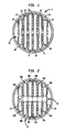
- a liquid distributor 1 is illustrated that includes a tray 10 having rows of apertures 12, 14, 16, 18, 20, 22 and 24.
- the apertures allow for downward passage of the descending liquid phase.
- a plurality of rows of pairs of vapour risers 26A,26B, 28A,28B, 30A,30B, 32A,32B, 34A,34B, and 36A,36B are provided to allow the ascending vapour phase to pass upwardly through tray 10.
- the pairs of vapour risers are arranged alternately with the rows of apertures.
- Spaced apart elongate liquid collectors 38, 40, 42, 44, 46 and 48 are provided above vapour risers 26A through 36A and 26B through 36B, and also between rows of apertures 12.
- the elongate liquid collectors 38 through 48 collect that part of the descending liquid phase which does not flow therebetween, and directs or channels it to a central region of the tray 10 via a distributor trough 50 having at its bottom rows of openings 52 through which the liquid is fed onto the tray 10.
- the tray 10 is circular so that it fits within the circular cross-section of a distillation column, not illustrated.
- the tray 10 is supported in a manner well known in the art that allows for its thermal expansion and contraction.
- the tray 10, as stated previously, is provided with rows of apertures 12 through 24 which are in the form of holes within tray 10. Liquid collects on tray 10, forms a pool and is redistributed to the next lowest bed through apertures 12.
- liquid collectors 38 through 48 are each of open, box-like construction and are provided with central rows of slots 54 to redistribute liquid into the distributor trough 50.
- the distributor trough 50 can be omitted, and in such case, liquid would simply fall onto a central region of tray 10, that is the region located beneath slots 54. Because of this, in such smaller applications, the slots in liquid collectors 38 through 48 can be replaced with openings at their bottom wall from which liquid would fall onto tray 10.
- Liquid collectors 38 through 48 also serve another function by covering (though not sealing) vapour riser pairs 26A, 26B through 36A, 36B. The vapour risers thus function as "hats".
- vapour riser pairs 26A, 26B through 36A, 36B could be separately “hatted” for the purpose of directing passage of vapour out of the risers and elongate liquid collectors 38 through 48 would simply lie across channel sections placed on the hats of vapour riser pairs 26A, 26B through 36A, 36B.
- vapour riser pairs 26A,26B through 36A, 36B are connected to distributor trough 50 to form a rigid structure that imparts rigidity or stiffness to the tray 10.
- each of vapour risers 26A,26B through 36A,36B are preferably of rectangular cross-section. Such rectangular construction acts like a box beam further to enhance the rigidity or stiffness of the tray 10.
- a combined structure is formed that is especially rigid.
- the distributor trough 50 provides a box beam at right angles or in an orthogonal direction to the rectangular cross-sections of paired vapour risers 26A,26B through 36A, 36B.
- the stiffness imparted by such construction allows for aluminum sheet metal construction with rivets, such as rivets 56 and 58, used to join the sheets together.
- elongate liquid collectors 38 through 48 are connected to vapour riser pairs 26A, 26B to 36A, 36B through sheet metal tabs 53.
- the bottom openings 52 are preferably sized larger than the apertures 12 in order to allow the redistribution of the liquid to a central part of tray 10.
- the total open area of bottom openings 52 is 60% of the entire open area provided by apertures 12.
- chevron-like collectors may be employed so that all, instead of part, of the descending liquid is caught in the collectors. In such case, all of the liquid would be directed/channeled from the collectors to a central region of the liquid distributor tray.
- a welded construction with the distributor trough 50 being connected to vapour risers such as vapour riser pairs 26A,26B through 36A,36B to support distributor trough 50 above tray 10 may be used instead.
Abstract
Description
Claims (7)
- A liquid distributor for a distillation column for distributing a descending liquid phase to be contacted with an ascending vapour phase within said distillation column, said liquid distributor comprising:a tray for collecting said descending liquid phase having rows of apertures for downward passage of said descending liquid phase;a plurality of rows of vapour risers located between said rows of apertures for passage of said ascending vapour phase. in an upward direction, through said tray; anda plurality of elongate liquid collectors, located above said rows of vapour risers and between said rows of apertures, for collecting at least part of the descending liquid phase before said descending liquid phase reaches said tray;said elongate liquid collectors having central redistribution means for redistributing the collected descending liquid phase over a central region of said tray.
- A liquid distributor according to claim 1, further comprising a distributor trough, located beneath said central redistribution means and over said central region, for collecting said part of said descending liquid phase, said trough having rows of openings for introducing the collected liquid onto said tray.
- A liquid distributor according to claim 2, wherein said distributor trough and said vapour risers are connected to one another.
- A liquid distributor according to claim 3, wherein:each of said vapour risers has a rectangular, transverse cross-section oriented at right angles to said distributor trough;said plurality of vapour risers comprise a plurality of pairs of vapour risers situated such that said distributor trough passes between said pairs of said vapour risers and is connected thereto; andthe said rectangular, transverse cross-section of said vapour risers increases in size as said vapour risers approach the diameter of said tray so that said vapour risers and said distributor trough form a structure that increases the stiffness of said tray in orthogonal directions.
- A liquid distributor according to claim 4, wherein said tray, said vapour risers, and said distributor trough are of sheet-metal construction and are riveted to one another.
- A liquid distributor according to any one of claims 2 to 5, wherein the open area of said rows of openings is about 60% of that of said rows of apertures.
- A liquid distributor tray according to any one of the preceding claims, wherein said central redistribution means comprises a central row of overflow slots defined within sidewalls of said rows of elongate liquid collectors.
Applications Claiming Priority (2)
| Application Number | Priority Date | Filing Date | Title |
|---|---|---|---|
| US08/858,643 US5935389A (en) | 1997-05-19 | 1997-05-19 | Liquid distributor tray |
| US858643 | 1997-05-19 |
Publications (2)
| Publication Number | Publication Date |
|---|---|
| EP0879626A2 true EP0879626A2 (en) | 1998-11-25 |
| EP0879626A3 EP0879626A3 (en) | 1999-07-14 |
Family
ID=25328805
Family Applications (1)
| Application Number | Title | Priority Date | Filing Date |
|---|---|---|---|
| EP98303923A Withdrawn EP0879626A3 (en) | 1997-05-19 | 1998-05-15 | Liquid distributor tray |
Country Status (3)
| Country | Link |
|---|---|
| US (1) | US5935389A (en) |
| EP (1) | EP0879626A3 (en) |
| JP (1) | JPH119901A (en) |
Cited By (5)
| Publication number | Priority date | Publication date | Assignee | Title |
|---|---|---|---|---|
| EP1345676A1 (en) * | 2000-12-21 | 2003-09-24 | Fluor Corporation | Methods and apparatus for mixing fluids |
| US7007932B2 (en) | 2003-07-25 | 2006-03-07 | Air Products And Chemicals, Inc. | Wall-flow redistributor for packed columns |
| SG150457A1 (en) * | 2007-08-21 | 2009-03-30 | Air Prod & Chem | Liquid collector and redistributor for packed columns |
| EP2826532A1 (en) | 2013-07-18 | 2015-01-21 | Sulzer Chemtech AG | A liquid mixing collector and a method for its use |
| EP3785783A1 (en) * | 2019-09-02 | 2021-03-03 | L'air Liquide, Societe Anonyme Pour L'etude Et L'exploitation Des Procedes Georges Claude | Column for separating gas/liquid containing a distribution device |
Families Citing this family (10)
| Publication number | Priority date | Publication date | Assignee | Title |
|---|---|---|---|---|
| US6749182B1 (en) * | 2002-11-25 | 2004-06-15 | Praxair Technology, Inc. | Bolted collector for vapor liquid contacting vessel |
| US7281525B2 (en) * | 2006-02-27 | 2007-10-16 | Briggs & Stratton Corporation | Filter canister family |
| CN100400132C (en) * | 2006-04-14 | 2008-07-09 | 天津大学 | Heat compensated oil collection tank |
| US7523923B2 (en) * | 2006-04-18 | 2009-04-28 | Shell Oil Company | Fluid distribution tray and method for the distribution of a highly dispersed fluid across a bed of contact material |
| KR20160052778A (en) | 2011-12-16 | 2016-05-12 | 에어 프로덕츠 앤드 케미칼스, 인코오포레이티드 | Liquid distributor with a mixer |
| US9630123B2 (en) | 2011-12-16 | 2017-04-25 | Air Products And Chemicals, Inc. | Liquid distributor with a mixer |
| KR101351638B1 (en) * | 2012-05-22 | 2014-01-16 | (주)에이엠티퍼시픽 | Liquid Splitter |
| US9004460B2 (en) | 2013-06-21 | 2015-04-14 | Praxair Technology, Inc. | Combined collector and distributor |
| FR3016533B1 (en) * | 2014-01-21 | 2016-01-15 | IFP Energies Nouvelles | DISPENSER PLATE FOR EXCHANGE COLUMN BETWEEN GAS AND LIQUID WITH LIQUID DEFLECTOR |
| CN104225947A (en) * | 2014-09-22 | 2014-12-24 | 潜江新亿宏有机化工有限公司 | Nickel-material packing rectifying tower for processing benzyl chloride |
Citations (6)
| Publication number | Priority date | Publication date | Assignee | Title |
|---|---|---|---|---|
| EP0169611A2 (en) * | 1984-07-25 | 1986-01-29 | Shell Internationale Researchmaatschappij B.V. | Column and process for gas/liquid contact |
| US5237823A (en) * | 1992-03-31 | 1993-08-24 | Praxair Technology, Inc. | Cryogenic air separation using random packing |
| WO1996026779A1 (en) * | 1995-03-02 | 1996-09-06 | Norton Chemical Process Products Corporation | High capacity trays |
| EP0736314A1 (en) * | 1995-04-04 | 1996-10-09 | L'air Liquide, Societe Anonyme Pour L'etude Et L'exploitation Des Procedes Georges Claude | Distributor for fluids |
| US5645770A (en) * | 1994-07-11 | 1997-07-08 | Koch Engineering Company, Inc. | Liquid collector-distributor device, system and method |
| DE19615645A1 (en) * | 1996-04-19 | 1997-10-23 | Bayer Ag | Device for distributing liquid in mass transfer columns |
Family Cites Families (9)
| Publication number | Priority date | Publication date | Assignee | Title |
|---|---|---|---|---|
| CH642566A5 (en) * | 1979-10-25 | 1984-04-30 | Sulzer Ag | TROUGH DEVICE FOR COLLECTING AND DISTRIBUTING THE LIQUID IN A COUNTERFLOW COLUMN. |
| US4472325A (en) * | 1983-06-13 | 1984-09-18 | The Dow Chemical Company | Liquid distributor apparatus for a vapor-liquid contact column |
| US4776989A (en) * | 1983-09-19 | 1988-10-11 | The Dow Chemical Company | Method and apparatus for liquid feed to liqiud distributors in fluid-liquid contacting towers |
| US4836989A (en) * | 1987-07-02 | 1989-06-06 | Mobil Oil Corporation | Distribution system for downflow reactors |
| US4820455A (en) * | 1987-08-13 | 1989-04-11 | Fractionation Research, Inc. | Apparatus for redistribution of vapor and liquid in a packed column |
| US4839108A (en) * | 1987-12-21 | 1989-06-13 | Mobil Oil Corp. | Liquid distribution device and pan |
| US4847430A (en) * | 1988-03-21 | 1989-07-11 | Institut Francais Du Petrole | Process for manufacturing a tertiary alkyl ether by reactive distillation |
| US5240652A (en) * | 1992-10-08 | 1993-08-31 | Praxair Technology, Inc. | Liquid distributor for a vapor-liquid contacting column |
| US5776316A (en) * | 1996-03-07 | 1998-07-07 | The Boc Group, Inc. | Liquid redistribution system |
-
1997
- 1997-05-19 US US08/858,643 patent/US5935389A/en not_active Expired - Fee Related
-
1998
- 1998-04-28 JP JP10117987A patent/JPH119901A/en not_active Withdrawn
- 1998-05-15 EP EP98303923A patent/EP0879626A3/en not_active Withdrawn
Patent Citations (6)
| Publication number | Priority date | Publication date | Assignee | Title |
|---|---|---|---|---|
| EP0169611A2 (en) * | 1984-07-25 | 1986-01-29 | Shell Internationale Researchmaatschappij B.V. | Column and process for gas/liquid contact |
| US5237823A (en) * | 1992-03-31 | 1993-08-24 | Praxair Technology, Inc. | Cryogenic air separation using random packing |
| US5645770A (en) * | 1994-07-11 | 1997-07-08 | Koch Engineering Company, Inc. | Liquid collector-distributor device, system and method |
| WO1996026779A1 (en) * | 1995-03-02 | 1996-09-06 | Norton Chemical Process Products Corporation | High capacity trays |
| EP0736314A1 (en) * | 1995-04-04 | 1996-10-09 | L'air Liquide, Societe Anonyme Pour L'etude Et L'exploitation Des Procedes Georges Claude | Distributor for fluids |
| DE19615645A1 (en) * | 1996-04-19 | 1997-10-23 | Bayer Ag | Device for distributing liquid in mass transfer columns |
Cited By (12)
| Publication number | Priority date | Publication date | Assignee | Title |
|---|---|---|---|---|
| EP1345676A1 (en) * | 2000-12-21 | 2003-09-24 | Fluor Corporation | Methods and apparatus for mixing fluids |
| EP1345676A4 (en) * | 2000-12-21 | 2006-07-05 | Fluor Corp | Methods and apparatus for mixing fluids |
| US7007932B2 (en) | 2003-07-25 | 2006-03-07 | Air Products And Chemicals, Inc. | Wall-flow redistributor for packed columns |
| SG150457A1 (en) * | 2007-08-21 | 2009-03-30 | Air Prod & Chem | Liquid collector and redistributor for packed columns |
| EP2826532A1 (en) | 2013-07-18 | 2015-01-21 | Sulzer Chemtech AG | A liquid mixing collector and a method for its use |
| WO2015007397A1 (en) | 2013-07-18 | 2015-01-22 | Sulzer Chemtech Ag | A liquid mixing collector and a method for its use |
| US9956500B2 (en) | 2013-07-18 | 2018-05-01 | Sulzer Chemtech Ag | Liquid mixing collector and a method for its use |
| EP3785783A1 (en) * | 2019-09-02 | 2021-03-03 | L'air Liquide, Societe Anonyme Pour L'etude Et L'exploitation Des Procedes Georges Claude | Column for separating gas/liquid containing a distribution device |
| CN112439225A (en) * | 2019-09-02 | 2021-03-05 | 乔治洛德方法研究和开发液化空气有限公司 | Gas/liquid separation column comprising a distribution device |
| FR3100320A1 (en) * | 2019-09-02 | 2021-03-05 | L'Air Liquide, Société Anonyme pour l'Etude et l'Exploitation des Procédés Georges Claude | Distribution device for a gas / liquid separation column |
| US11426676B2 (en) | 2019-09-02 | 2022-08-30 | L'air Liquide, Societe Anonyme Pour L'etude Et L'exploitation Des Procedes Georges Claude | Gas/liquid separation column containing a dispensing device |
| CN112439225B (en) * | 2019-09-02 | 2024-02-13 | 乔治洛德方法研究和开发液化空气有限公司 | Gas/liquid separation column comprising a distribution device |
Also Published As
| Publication number | Publication date |
|---|---|
| US5935389A (en) | 1999-08-10 |
| JPH119901A (en) | 1999-01-19 |
| EP0879626A3 (en) | 1999-07-14 |
Similar Documents
| Publication | Publication Date | Title |
|---|---|---|
| EP0737498B1 (en) | Gas-liquid contacting tray with side discharging triangular downcomers | |
| KR101044979B1 (en) | Liquid collector and redistributor for packed columns | |
| US5935389A (en) | Liquid distributor tray | |
| US6722639B2 (en) | Liquid distributor in mass transfer column and method of installation and use | |
| US5547617A (en) | Apparatus for increasing effective active area | |
| US5702647A (en) | Multiple downcomer high performance tray assembly | |
| US7007932B2 (en) | Wall-flow redistributor for packed columns | |
| US8317166B2 (en) | Liquid collection and distribution device for mass transfer column and process involving same | |
| US5707563A (en) | V-module fractionation tray | |
| JPS6349521B2 (en) | ||
| US5762668A (en) | Apparatus and method for deentrainment in a chemical process tower | |
| US9956500B2 (en) | Liquid mixing collector and a method for its use | |
| US6131891A (en) | Fractionation column containing stacked fractionation trays | |
| US6293528B1 (en) | Fractionation apparatus with low surface area grid above tray deck | |
| US8052126B2 (en) | Liquid distribution in co-current contacting apparatuses | |
| US6095504A (en) | Supports for stacked fractionation tray end pieces | |
| US6116583A (en) | Nestable fractionation tray antipenetration pans | |
| CA2146704C (en) | Gas-liquid contacting tray with side discharging triangular downcomers | |
| AU717982B2 (en) | Apparatus for increasing effective active area | |
| CA2353183A1 (en) | Fractionation apparatus with low surface area grid above tray deck |
Legal Events
| Date | Code | Title | Description |
|---|---|---|---|
| PUAI | Public reference made under article 153(3) epc to a published international application that has entered the european phase |
Free format text: ORIGINAL CODE: 0009012 |
|
| AK | Designated contracting states |
Kind code of ref document: A2 Designated state(s): DE FR GB |
|
| AX | Request for extension of the european patent |
Free format text: AL;LT;LV;MK;RO;SI |
|
| PUAL | Search report despatched |
Free format text: ORIGINAL CODE: 0009013 |
|
| AK | Designated contracting states |
Kind code of ref document: A3 Designated state(s): AT BE CH CY DE DK ES FI FR GB GR IE IT LI LU MC NL PT SE |
|
| AX | Request for extension of the european patent |
Free format text: AL;LT;LV;MK;RO;SI |
|
| 17P | Request for examination filed |
Effective date: 20000110 |
|
| AKX | Designation fees paid |
Free format text: DE FR GB |
|
| STAA | Information on the status of an ep patent application or granted ep patent |
Free format text: STATUS: THE APPLICATION IS DEEMED TO BE WITHDRAWN |
|
| 18D | Application deemed to be withdrawn |
Effective date: 20031202 |