EP0878792B1 - Coded data reading and recording apparatus - Google Patents
Coded data reading and recording apparatus Download PDFInfo
- Publication number
- EP0878792B1 EP0878792B1 EP98108820A EP98108820A EP0878792B1 EP 0878792 B1 EP0878792 B1 EP 0878792B1 EP 98108820 A EP98108820 A EP 98108820A EP 98108820 A EP98108820 A EP 98108820A EP 0878792 B1 EP0878792 B1 EP 0878792B1
- Authority
- EP
- European Patent Office
- Prior art keywords
- data
- code
- pattern image
- code pattern
- block
- Prior art date
- Legal status (The legal status is an assumption and is not a legal conclusion. Google has not performed a legal analysis and makes no representation as to the accuracy of the status listed.)
- Expired - Lifetime
Links
Images


Classifications
-
- G—PHYSICS
- G11—INFORMATION STORAGE
- G11B—INFORMATION STORAGE BASED ON RELATIVE MOVEMENT BETWEEN RECORD CARRIER AND TRANSDUCER
- G11B19/00—Driving, starting, stopping record carriers not specifically of filamentary or web form, or of supports therefor; Control thereof; Control of operating function ; Driving both disc and head
- G11B19/02—Control of operating function, e.g. switching from recording to reproducing
-
- G—PHYSICS
- G06—COMPUTING; CALCULATING OR COUNTING
- G06K—GRAPHICAL DATA READING; PRESENTATION OF DATA; RECORD CARRIERS; HANDLING RECORD CARRIERS
- G06K1/00—Methods or arrangements for marking the record carrier in digital fashion
- G06K1/12—Methods or arrangements for marking the record carrier in digital fashion otherwise than by punching
- G06K1/121—Methods or arrangements for marking the record carrier in digital fashion otherwise than by punching by printing code marks
-
- G—PHYSICS
- G06—COMPUTING; CALCULATING OR COUNTING
- G06K—GRAPHICAL DATA READING; PRESENTATION OF DATA; RECORD CARRIERS; HANDLING RECORD CARRIERS
- G06K19/00—Record carriers for use with machines and with at least a part designed to carry digital markings
- G06K19/06—Record carriers for use with machines and with at least a part designed to carry digital markings characterised by the kind of the digital marking, e.g. shape, nature, code
- G06K19/06009—Record carriers for use with machines and with at least a part designed to carry digital markings characterised by the kind of the digital marking, e.g. shape, nature, code with optically detectable marking
- G06K19/06037—Record carriers for use with machines and with at least a part designed to carry digital markings characterised by the kind of the digital marking, e.g. shape, nature, code with optically detectable marking multi-dimensional coding
-
- G—PHYSICS
- G11—INFORMATION STORAGE
- G11B—INFORMATION STORAGE BASED ON RELATIVE MOVEMENT BETWEEN RECORD CARRIER AND TRANSDUCER
- G11B19/00—Driving, starting, stopping record carriers not specifically of filamentary or web form, or of supports therefor; Control thereof; Control of operating function ; Driving both disc and head
- G11B19/02—Control of operating function, e.g. switching from recording to reproducing
- G11B19/12—Control of operating function, e.g. switching from recording to reproducing by sensing distinguishing features of or on records, e.g. diameter end mark
-
- G—PHYSICS
- G11—INFORMATION STORAGE
- G11B—INFORMATION STORAGE BASED ON RELATIVE MOVEMENT BETWEEN RECORD CARRIER AND TRANSDUCER
- G11B20/00—Signal processing not specific to the method of recording or reproducing; Circuits therefor
- G11B20/00086—Circuits for prevention of unauthorised reproduction or copying, e.g. piracy
-
- G—PHYSICS
- G11—INFORMATION STORAGE
- G11B—INFORMATION STORAGE BASED ON RELATIVE MOVEMENT BETWEEN RECORD CARRIER AND TRANSDUCER
- G11B7/00—Recording or reproducing by optical means, e.g. recording using a thermal beam of optical radiation by modifying optical properties or the physical structure, reproducing using an optical beam at lower power by sensing optical properties; Record carriers therefor
- G11B7/002—Recording, reproducing or erasing systems characterised by the shape or form of the carrier
- G11B7/0033—Recording, reproducing or erasing systems characterised by the shape or form of the carrier with cards or other card-like flat carriers, e.g. flat sheets of optical film
Definitions
- This invention relates to a code reading and recording apparatus for reading a code pattern image recorded on a recording medium as an image that can be picked up and read electronically.
- EP 0,670,555 A1 discloses a system for recording digitized data on a recording medium and reproducing the recorded data from the medium.
- data are recorded as an optically readable code pattern image on a recording medium such as a sheet of paper by printing. While this system provides a number of advantages including that the recorded data can be reproduced in a simple manner, it has its own drawbacks. For example, the recorded code pattern image can easily be copied to fraudulently use the information contained in the image and infringe the copyright on the information if the information constitutes an intellectual property unless some protective measures are taken.
- known techniques for preventing recorded information from being copied include adding a header to the information and making the header contain control data that permits or prohibits printing the information for copying. Such a technique may be applied to the above disclosed system to protect the recorded information against any fraudulent use.
- a header or a footer for permitting or prohibiting copying can be added to the proper information only at the cost of reducing the storage area for storing information and hence, in many cases, partly eliminating the information to be stored. Therefore, the use of such a header or a footer is against a maximal exploitation of the data storage capacity of a system of the type under consideration.
- the object of the present invention to provide a code reading and recording apparatus that can effectively prevent any code pattern image from being fraudulently copied and protect the copyright of the information contained in the image, if the information constitutes an intellectual property, without reducing the quantity of information to be recorded by ingeniously utilizing the format of printing a code pattern image.
- a code reading and recording apparatus comprising:
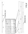
- a code pattern image 10 designed for the purpose of the invention and printed on a recording medium such as a sheet of paper comprises a plurality of regularly arranged blocks 12, each having a set of predetermined unit dots. From a macroscopic point of view, each of the blocks having a set of predetermined number of dots will be recognized as a block having a given density.
- FIG. 2 is an enlarged view of a single block of the blocks of FIG. 1.
- the block 12 contains a combination of a data dot pattern 14 arranged in accordance with the contents of the data to be recorded and a block header pattern 16 arranged with a predetermined positional relationship relative to the data dot pattern 14 and carrying information including the address of the block.
- the block is provided with markers 18 and a matching dot pattern 20 that are arranged at respective predetermined positions relative to the block.
- the markers 18 are located at the four corners of the block and the matching dot pattern 20 is positioned on the lateral boundaries separating the block from the adjacent blocks.
- the block header pattern 16 also has a predetermined positional relationship relative to the markers 18 and located at the top and the bottom of the block in FIG. 2. Note that all the dots of the matching dot pattern 20, the block header pattern 16 and the data dot pattern 14 have an identical size.
- Each of the markers 18 has an area greater than that of each of the dots.
- the markers may be in the form of a circle having a diameter five times greater than that of the dots on the recording medium.
- Modulation refers to a process of limiting the number of consecutively arranged dots so that dots and markers may be discriminated without fail. If, for example, the marker has a diameter five times greater than the dot, the number of consecutively arranged dots has to be equal to or less than four. Thus, the modulation will be a 4-5 modulation where a redundancy bit is added to each 4-bit data. Typically, a modulation table will be selected out of a number of prearranged modulation tables in order to ensure that the largest number of consecutive dots does not exceed four.
- each of the crossings where a dot is found represents "1", whereas each of the crossings where no dot is found represents "0".
- the block header pattern 16 can be made to carry information on the modulation table being used and control data in addition to the information on the block address. Therefore, the data of the block header pattern are non-modulated data.
- the code pattern image 10 will be taken up for use typically by manually scanning the image by means of a code pattern image input device (not shown).
- a code pattern image input device not shown.
- the locations of the markers 18 are detected and used as references for accurately determining the position of the code in a picked-up CCD image covering a plurality of frames before the data dot pattern 14 in the block 12 is read.
- the matching dot pattern 20 arranged between the block and the related adjacent blocks are searched to determine the values of the coordinates of the centorid of each of the dots of the matching dot pattern 20.
- FIG. 3 is a schematic block diagram of a first embodiment of code reading and recording apparatus 22 according to the invention.
- This embodiment of code reading and recording apparatus 22 comprises a code pattern image input device 24, a multiple-value-to-binary-value converter 26, a decoder 28, a reproducing unit 30, an operation control data extracting unit 32, an encoding operation controller 34, an encoder 36 and a printer 38.
- the code pattern image input device 24 may be an optical device or a CCD unit for picking up and reading a code pattern image 10.
- the multiple-value-to-binary-value converter 26 transforms the multiple-value image data picked up by the code pattern image input device 24 into binary data.
- the decoder 28 restores the original multi-media data including audio data, video data and digital code data and recorded on the recording medium as a code pattern image 10 from the binary image data produced by the multiple-value-to-binary value converter 26.
- the decoder 28 includes a dot detector 28A, a code demodulator 28B, a data deinterleaver 28C, an error corrector 28D and an expander 28E.
- the dot detector 28A detects the dots in each block of the code pattern image 10 by means of a known method from the image data that have been transformed into binary data by the multiple-value-to-binary value converter 26.
- the code demodulator 28B demodulates the dot data modulated at the time of recording and detected by the dot detector 28A.
- the data deinterleaver 28C performs deinterleaving on the data demodulated by the code demodulator 28B, which has been interleaved, when recorded, in order not to contain burst errors. The data is thereby restored to the form it has before it was subjected to interleaving.
- the term "interleaving” as used herein refers to dividing data into parts having a predetermined length and arranging them in such a way that they may be shuffled appropriately as seen from FIG. 4.
- the error corrector 28D corrects any errors in the data deinterleaved by the data deinterleaver 28C.
- the expander 28E expands the data corrected by the error corrector 28D to restore the original data because the data was compressed at the time of recording.
- the reproducing unit 30 outputs the original data including audio data, video data and digital code data that has been deinterleaved, corrected for errors and expanded by the decoder 28.
- the operation control data extracting unit 32 extracts control data from the dots detected by the dot detector 28A of the decoder 28 or the data processed in each of the processing steps as will be described hereinafter.
- the encoding operation controller 34 controls the encoder 36 and permits or prohibits an encoding operation by the encoder 36 according to the operation control data extracted by the operation control data extracting unit 32.
- the encoder 36 is adapted to perform an operation of compressing a data, adding an error correcting code to it, interleaving it and then modulating it.
- it includes a compressor 36A, an error correction code affixing unit 36B, a data interleaver 36C, a code modulator 36D and a printable image data generator 36E.
- the compressor 36A compresses the data fed from the expander 28E of the decoder 28.
- the error correction code affixing unit 36B adds an error correction code to the data compressed by the compressor 36A.
- the data interleaver 36C rearranges the data having an error correction code affixed to it by the error correction code affixing unit 36B so as to prevents any consecutive reading errors (burst error) from occurring due to smears on the printed surface of a recording medium that have been given rise to for some reason or other.
- the code modulator 36D modulates the data rearranged by the data interleaver 36C to produce a modulated data.
- the printable image data generator 36E generates a printable image data to be used for printing on a recording medium from the encoded data that has been modulated by the code modulator 36D.
- the printer 38 prints the printable image data generated by the printable image data generator 36E of the encoder 36 as a code pattern image 10 on a recording medium such as a sheet of paper.
- the encoding operation controller 34 permits or prohibits the current encoding operation of the encoder 36 according to the operation control data extracted by the operation control data extracting unit 32.
- the encoder 36 is made unoperational. Therefore, with this arrangement, the code pattern image of the data can be prevented from being copied in a simple manner.
- the encoding operation controller 34 may be made to control not only the encoder 36 but also the decoder 28 so that the data on a code pattern image will be neither decoded nor reproduced when copying the image is prohibited.
- FIG. 5 is a schematic flow chart of the above described operation of the first embodiment of code reading and recording apparatus. Note that the apparatus reads a code pattern image 10 printed on a recording medium and prints an identical code pattern image on some other recording medium.
- the code pattern image input device 24 picks up and reads the code pattern image 10 printed on a recording medium (not shown) (Step S10). Then, the multi-valued image data that has been picked up is then transformed into a binary value data by the multiple-value-to-binary value converter 26 (Step S12). The binarized image data is then fed to the dot detector 28A of the decoder 28, where the dot detectors 28A detects the dots of the code pattern image as the smallest units (Step S14).
- the operation control data extracting unit 32 extracts the operation control data contained in the image data.
- An operation control data is a data describing one or more than one characteristic aspects of the physical structure of the code pattern image 10. For example, it may be a block header pattern 16 contained in the code pattern image 10 that describes how the blocks 12 of the code pattern image are arranged as will be described in greater detail hereinafter.
- the encoding operation controller 34 determines if the operation control data permits copying the image or not according to the data on the arrangement of the blocks (Step S16). If it is determined in Step S16 that the operation control data does not permit copying the image, the entire operation will be terminated at this point.
- Step S16 If, on the other hand, it is determined in Step S16 that the operation control data permits copying the image, the code demodulator 28B of the decoder 28 demodulates the modulated data that comprised the detected dots (Step S18). Since the data has been interleaved (rearranged) in order to prevent any loss of data from taking place due to consecutive dot detection errors, the data deinterleaver 28C deinterleaves (restores the original arrangement of) the data (Step S20). Then, the error corrector 28D corrects any errors in the data (Step S22) and the expander 28E expands the data to completely restore the original multi-media data (Step S24).
- the compressor 36A compresses the restored multi-media data (Step S26) and the error correction code affixing unit 36B adds an error correction code to the data (Step S28).
- the data interleaver 36C interleaves (rearranges) the data in order to prevent an loss of data from taking place due to consecutive dot detection errors (Step S30) and the code modulator 36D modulates the code (Step S32).
- the data that has been compressed, affixed with an error correction code, rearranged and modulated is utilized by the printable image data generator 36E to produce a corresponding code pattern image containing markers in order to print the image on a recording medium (Step S34).
- the printer 38 then prints the code pattern image (Step S36).
- the one or more than one characteristic aspects of the physical structure of the picked up code pattern image may advantageously be used so that, unlike any known comparable conventional methods, the data of the code pattern image that should not be copied is exempted from the operation of being demodulated and deinterleaved to improve the overall efficiency of the embodiment.
- the code pattern image input device 24 picks up and reads the code pattern image 10 printed on the recording medium (Step S10). Then, the multi-valued image data that has been picked up is then transformed into a binary value data (Step S12). The binarized image data is then fed to the dot detector 28A, which detects the dots of the code pattern image as the smallest units (Step S14) and the data on the address arrangement of the block 12 in the code pattern image 10 is used to determine if copying the code pattern image is permitted or not (Step S16).
- Step S16 If it is determined in Step S16 that copying the code pattern image is permitted, the printable image data is directly drawn out of the data that has been subjected to a multiple-value-to-binary value transformation and used for dot detection (Step S34) and then the image will be printed (Step S36).
- the operation control data of this embodiment is a data on the arrangement of blocks obtained from the block header pattern 16 or, in other words, a data describing one or more than one characteristic aspects of the physical structure of the code pattern image so that the head or the footer does not have to contain such an operation control data as shown in FIG. 8 and hence more image data can be stored in the code pattern image.
- a code pattern image as shown in FIG. 9 comprises a total of 2 ⁇ 8 rectangularly parallelepipedic blocks containing respective addresses in the inside and that 8 blocks are used as a unit for interleaving.
- FIG. 11 shows the block arrangement for permitting copying the code pattern image only once.
- the block addresses of the third and fourth blocks of each unit of eight blocks for interleaving are inverted from the arrangement of FIG. 9 for permitting copying the code pattern image without restrictions.
- FIG. 12 shows the block arrangement for permitting copying the code pattern image twice.
- the block addresses of the fifth and sixth blocks of each unit of eight blocks for interleaving are inverted from the arrangement of FIG. 9 for permitting copying the code pattern image without restrictions.
- the encoding operation controller 34 controls the encoder 36 so as to make it rearrange the code pattern image with the block arrangement of FIG. 12 into that of FIG. 11 when reading and printing the code pattern image.
- the encoding operation controller 34 controls the encoder 36 so as to make it rearrange the code pattern image with the block arrangement of FIG. 11 into that of FIG. 10 when reading and printing the code pattern image.
- the encoding operation controller 34 forbids the encoder 36 to operate and does not allow to copy the code pattern image by printing because copying the image is prohibited.
- the operation of copying the original code pattern image can be controlled for the number of copies by unequivocally defining the arrangement of block addresses as shown in FIG. 11 or 12 that is different from the block address arrangement for permitting copying the code pattern image without restrictions and the arrangement for totally prohibiting copying the code pattern image.
- FIGS. 1 and 2 can also be used with the second embodiment.
- this second embodiment of code reading and recording apparatus according to the invention has a configuration as shown in FIG. 3 and described above for the first embodiment.
- the flow chart of the operation of reading a printed code pattern image and printing an identical code pattern image on a recording medium as illustrated in FIG. 5 is also applicable to the second embodiment.
- the block address arrangement of FIG. 14 obtained by adding "1" to each of the addresses of FIG. 9 so that the addresses are arranged in the ascending order and starts from “2” may be used to tell that copying the image is permitted for only once.
- the block address arrangement of FIG. 15 obtained by adding "2" to each of the addresses of FIG. 9 so that the addresses are arranged in the ascending order and starts from "3” may be used to tell that copying the image is permitted for twice.
- the encoding operation controller 34 controls the encoder 36 so as to make it rearrange the code pattern image with the block arrangement of FIG. 15 into that of FIG. 14 when reading and printing the code pattern image.
- the encoding operation controller 34 controls the encoder 36 so as to make it rearrange the code pattern image with the block arrangement of FIG. 14 into that of FIG. 13 when reading and printing the code pattern image.
- the encoding operation controller 34 forbids the encoder 36 to operate and does not allow to copy the code pattern image by printing because copying the image is prohibited.
- the operation of copying the original code pattern image can be controlled for the number of copies by unequivocally defining the arrangement of block addresses as shown in FIG. 14 or 15 that is different from the block address arrangement for permitting copying the code pattern image without restrictions and the arrangement for totally prohibiting copying the code pattern image.
- an operation control data can be conveyed by the arrangement of block addresses to make the code reading and recording apparatus efficiently realize a status where copying an code pattern image is permitted or prohibited without reducing the data storage area in the code pattern image.
- this third embodiment of code reading and recording apparatus has a configuration as shown in FIG. 3 and described above for the first embodiment.
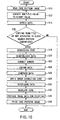
- FIG. 16 is a schematic flow chart of the operation of the third embodiment of code reading and recording apparatus. Note that the apparatus reads a code pattern image 10 printed on a recording medium and prints an identical code pattern image on some other recording medium.
- the code pattern image input device 24 picks up and reads the code pattern image 10 printed on a recording medium (not shown) (Step S10). Then, the multi-valued image data that has been picked up is then transformed into a binary value data by the multiple-value-to-binary value converter 26 (Step S12). The binarized image data is then fed to the dot detector 28A of the decoder 28, where the dot detectors 28A detects the dots of the code pattern image as the smallest units (Step S14). At this stage, the embodiment recognizes the block header pattern contained in the code pattern image.
- the block header comprises 11 bits, of which 6 bits are used for block addresses 16A and 4 bits out of the remaining 5 bits are used to indicate the number of blocks contained in an interleaved unit that have been rearranged according to a restoration parameter data (hereinafter referred to as interleaved block unit 16B).
- interleaved block unit 16B a restoration parameter data
- the interleaved block unit 16B is typically used to assign a same and identical data to all the blocks.
- a control data can be conveyed by the block header pattern and retrieved by the apparatus by placing unique data in some of the blocks that are supposed to contain a common data.
- the last bit of the 11-bit block header is used to indicate the mode of modulation 16C.
- the operation control data extracting unit 32 compares the blocks of the block header pattern with each other to detect any differences existing there in order to determine if copying the code pattern image is prohibited or permitted. If it is determined that the operation control data does not permit copying the image, the entire operation will be terminated at this point.
- the code demodulator 28B of the decoder 28 demodulates the modulated data that comprised the detected dots (Step S18). Since the data has been interleaved (rearranged) in order to prevent any loss of data from taking place due to consecutive dot detection errors, the data deinterleaver 28C deinterleaves (restores the original arrangement of) the data (Step S20). Then, the error corrector 28D corrects any errors in the data (Step S22) and the expander 28E expands the data to completely restore the original multi-media data (Step S24).
- the compressor 36A compresses the restored multi-media data (Step S26) and the error correction code affixing unit 36B adds an error correction code to the data (Step S28).
- the data interleaver 36C interleaves (rearranges) the data in order to prevent an loss of data from taking place due to consecutive dot detection errors (Step S30) and the code modulator 36D modulates the code (Step S32).
- the data that has been compressed, affixed with an error correction code, rearranged and modulated is utilized by the printable image data generator 36E to produce a corresponding code pattern image containing markers in order to print the image on a recording medium (Step S34).
- the printer 38 then prints the code pattern image (Step S36).
- the interleaved block unit 16B comprises a total of 8 blocks and, when copying a code pattern image is permitted without restrictions, a value of "8" is set in the interleaved block units 16B of all the block headers of block "1" through block "16". When, on the other hand, copying the code pattern image is prohibited, a value of "0" is set in the interleaved block unit 16B of each of the block headers of blocks "5", "6", “13", and "14" as shown in FIG. 19.
- this fourth embodiment of code reading and recording apparatus has a configuration as shown in FIG. 3 and described above for the first embodiment.
- FIG. 20 is a schematic flow chart of the operation of the fourth embodiment of code reading and recording apparatus. Note that the apparatus reads a code pattern image 10 printed on a recording medium and prints an identical code pattern image on some other recording medium.
- the code pattern image input device 24 picks up and reads the code pattern image 10 printed on a recording medium (not shown) (Step S10). Then, the multi-valued image data that has been picked up is then transformed into a binary value data by the multiple-value-to-binary value converter 26 (Step S12). The binarized image data is then fed to the dot detector 28A of the decoder 28, where the dot detectors 28A detects the dots of the code pattern image as the smallest units (Step S14). The code demodulator 28B of the decoder 28 demodulates the modulated data recognized from the detected dots (Step S18).
- the modulation table to be used is selected out of a number of tables at the time of the modulating operation according to the control data for permitting or prohibiting copying the code pattern image so that the demodulator may recognize the control data by referring to the conversion table to be referred to for the demodulating operation.
- This procedure will be described by referring to an example where code pattern is provided by transforming a 3-bit data into a redundant 5-bit data.
- a 5-bit data format can be used for 32 different data.
- a 3-bit data format can be used for 8 different data. Therefore, with this embodiment, a 3-bit to 5-bit conversion table (equivalent with a 3-bit ⁇ --> 5-bit conversion table) is used for only 8 different data although it can be used for 32 different data.
- FIG. 22 shows a 3-bit ⁇ --> 5-bit conversion table to be used for permitting copying without restrictions.
- FIG. 23 shows a 3-bit ⁇ --> 5-bit conversion table to be used for prohibiting copying a code pattern image. Since the 5-bit data to be used for permitting copying a code pattern image are totally different from those to be used for prohibiting copying the image, the two instances can be clearly discriminated by recognizing the modulated data. Note that, in FIGS. 22 and 23, it is so arranged that the largest number of consecutive "1" in the modulated data does not exceed four in order to prevent any data dots from being erroneously recognized as a marker 18 in the operation of recognizing blocks 12 by means of markers 18 as in the case of FIG. 2.
- Step S40 the operation control data extracting unit 32 determines if copying the code pattern image is permitted or prohibited by recognizing the modulated data. If it is determined in Step S40 that copying the image is prohibited, the entire operation will be terminated at this point.
- the data deinterleaver 28C deinterleaves (restores the original arrangement of) the data (Step S20). Then, the error corrector 28D corrects any errors in the data (Step S22) and the expander 28E expands the data to completely restore the original multi-media data (Step S24).
- the compressor 36A compresses the restored multi-media data (Step S26) and the error correction code affixing unit 36B adds an error correction code to the data (Step S28).
- the data interleaver 36C interleaves (rearranges) the data in order to prevent an loss of data from taking place due to consecutive dot detection errors (Step S30) and the code modulator 36D modulates the code (Step S32).
- the data that has been compressed, affixed with an error correction code, rearranged and modulated is utilized by the printable image data generator 36E to produce a corresponding code pattern image containing markers in order to print the image on a recording medium (Step S34).
- the printer 38 then prints the code pattern image (Step S36).
- two 5-bit data of (10001) 2 and (10100) 2 are used respectively for two 3-bit data of (001) 2 and (100) 2 in order to tell that copying the code pattern image is prohibited in place of (00001) 2 and (00100) 2 in FIG. 22 telling that copying the code pattern image is permitted.
- FIGS. 1 and 2 can also be used with the fifth embodiment.
- this fifth embodiment of code reading and recording apparatus according to the invention has a configuration as shown in FIG. 3 and described above for the first embodiment.
- FIG. 25 is a schematic flow chart of the operation of the fifth embodiment of code reading and recording apparatus. Note that the apparatus reads a code pattern image 10 printed on a recording medium and prints an identical code pattern image on some other recording medium.
- the code pattern image input device 24 picks up and reads the code pattern image 10 printed on a recording medium (not shown) (Step S10). Then, the multi-valued image data that has been picked up is then transformed into a binary value data by the multiple-value-to-binary value converter 26 (Step S12). The binarized image data is then fed to the dot detector 28A of the decoder 28, where the dot detectors 28A detects the dots of the code pattern image as the smallest units (Step S14).
- the markers 18 in the blocks of the code pattern image 10 are recognized. If a plurality of dot patterns are predefined for markers 18, they can be utilized for control data so that the operation of controlling the process of copying a code pattern image can be realized by looking into the dot code patterns of the markers used for the code pattern image.
- Step S42 the operation control data extracting unit 32 determines if copying the code pattern image is permitted or prohibited by recognizing the dot code patterns of the markers. If it is determined in Step S42 that copying the image is prohibited, the entire operation will be terminated at this point.
- the code demodulator 28B of the decoder 28 demodulates the modulated data that comprised the detected dots (Step S18). Since the data has been interleaved (rearranged) in order to prevent any loss of data from taking place due to consecutive dot detection errors, the data deinterleaver 28C deinterleaves (restores the original arrangement of) the data (Step S20). Then, the error corrector 28D corrects any errors in the data (Step S22) and the expander 28E expands the data to completely restore the original multi-media data (Step S24).
- the compressor 36A compresses the restored multi-media data (Step S26) and the error correction code affixing unit 36B adds an error correction code to the data (Step S28).
- the data interleaver 36C interleaves (rearranges) the data in order to prevent an loss of data from taking place due to consecutive dot detection errors (Step S30) and the code modulator 36D modulates the code (Step S32).
- the data that has been compressed, affixed with an error correction code, rearranged and modulated is utilized by the printable image data generator 36E to produce a corresponding code pattern image containing markers in order to print the image on a recording medium (Step S34).
- the printer 38 then prints the code pattern image (Step S36).
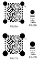
- FIGS. 26A and 26B and FIGS. 27A and 27B show examples of dot patterns that can be used for markers 18.
- each marker 18 has a diameter equal to four times of the diameter of each black dot in the blocks that represents a 1-bit data. The markers may be used to indicate that copying the code pattern image is permitted.
- each marker 18 has a diameter equal to five times of the diameter of each black dot in the blocks that represents a 1-bit data. The markers may be used to indicate that copying the code pattern image is prohibited.
- a control data can be conveyed by selecting appropriate physical structural characteristics of the code pattern image, which are the sizes of the markers contained in the code pattern image 10 in the above description, so that if copying the code pattern image is permitted or not can be determined efficiently by simply recognizing the sizes of the markers.
- the data storage area in the code pattern image is not reduced and hence can store a large volume of data.
- the sizes of the markers are used as physical structural characteristics in the above description, the gap separating the blocks, the dot size, the distance between adjacent markers an/or other physical structure characteristics may alternatively be used for the purpose of the invention.
- a code pattern image printed on a recording medium as data adapted to be picked up and read are actually picked up and read by the reading section.
- the decoder decodes the code pattern image read by the reading section and retrieves the original data.
- the encoder transforms the data retrieved by the decoder into an image data of a code pattern image and the recording section prints the transformed image data on a predetermined recording medium as code pattern image adapted to be picked up and read.
- the code pattern image is made to contain an operation data for permitting or prohibiting the operation of the encoder so that the operation control data extracting section extracts the operation data from the code pattern image read by the reading section and the operation control section permits or prohibits the operation of the encoder according to the operation data extracted by the operation control data extracting section.
- the operation control data extracting section extracts the operation control data from the code pattern image to permit or prohibit the operation of the encoder in order to properly protect the copyright of the original data.
- the apparatus can control its own operation once it realizes the physical structural characteristics of the code pattern image if it does not recognize all the internal data to consequently protect the copyright of the original data.
- the code pattern image can be thoroughly exploited for storing proper data because the operation control data does not require any data storage area.
- a code reading and recording apparatus characterized in that the code pattern image is realized by arranging a plurality of adjacently locatable blocks (12), each comprising a data dot pattern (14) of a plurality of dot arranged according to the data to be transmitted, a marker (18) for recognizing the block and a block header pattern (16) containing a block address data (16A) for indicating the address of the arranged block, the data dot pattern, the marker and the block header pattern being arranged with a predetermined positional relationship, and that physical structural characteristics of the code pattern image are used as information indicating how addresses are allocated to the blocks of the code pattern image.
- the code pattern image is realized by arranging a plurality of adjacently locatable blocks, each of which comprises a data dot pattern of a plurality of dot arranged according to the data to be transmitted, a marker for recognizing the block and a block header pattern containing a block address data for indicating the address of the block arranged, and the data dot pattern, the marker and the block header pattern are arranged with a predetermined positional relationship. Additionally, physical structural characteristics of the code pattern image as described in (2) above are used to indicate how addresses are allocated to the blocks of the code pattern image.
- the apparatus identifies the blocks by recognizing the markers and, once the apparatus recognizes the block header pattern, it can takes in the operation control data contained in the image so that it can control its own operation without recognizing the data contained in the blocks.
- the code pattern image can be thoroughly exploited for storing proper data because the operation control data does not require any data storage area.
- a code reading and recording apparatus characterized in that the information indicating how addresses are allocated is extracted at least by using as a unit of operation a deinterleaving process of restoring the original arrangement of the data for dispersing them according to a predetermined rule in the interleaving process performed at the time of printing and recording the code pattern image.
- the information indicating how block addresses are allocated as described in (3) is extracted at least for each code pattern image that corresponds to the data volume of an interleaving process of arranging the data to disperse them according to a predetermined rule performed at the time of printing and recording the code pattern image.
- the operation control data can be obtained by recognizing only the information on how block addresses are allocated in the code pattern image that corresponds to the interleaving process without recognizing the entire code pattern image.
- the code pattern image can be thoroughly exploited for storing proper data because the operation control data does not require any data storage area.
- a code reading and recording apparatus characterized in that the code pattern image is realized by arranging a plurality of adjacently locatable blocks (12), each comprising a data dot pattern (14) of a plurality of dot arranged according to the data to be transmitted, a marker (18) for recognizing the block and a block header pattern (16) containing a block address data (16A) for indicating the address of the arranged block, the data dot pattern, the marker and the block header pattern being arranged with a predetermined positional relationship, the block header pattern containing information on restoration parameters (16B) necessary for restoring the encoded data and commonly used for the block header patterns of the blocks, and that the differences among the data restoration parameters contained in each block header pattern are used as information indicating how addresses are allocated to the blocks of the code pattern image.
- the block header pattern contains information on restoration parameters necessary for restoring the encoded data and commonly used for the block header patterns of the blocks and the differences among the data restoration parameters contained in each block header pattern are used as information indicating how addresses are allocated to the blocks of the code pattern image.
- the block header pattern 16 contains the mode of modulation 16C, the interleaved block unit 16B and other information, of which the interleaved block unit shows a same and identical value for all the interleaved blocks. Therefore, the block header patterns can be made to carry an operation control data by varying the value in some of the blocks on purpose.
- the operation control data can be retrieved to control the operation of the code reading and recording apparatus by simply recognizing the differences among a plurality of block header patterns without recognizing the data contained in the blocks.
- the code pattern image can be thoroughly exploited for storing proper data because the operation control data does not require any data storage area.
- a code reading and recording apparatus characterized in that the data is a data modulated to include predetermined redundant bits and the code pattern image is printed/recorded as an image adapted to be picked up and read and corresponding to the values of the bits of the modulated data and that the data on the physical structural characteristics of the code pattern image is a data on the mode of modulation relating to how predetermined redundant bits are added to the bits of the proper data.
- the data on the physical structural characteristics of the code pattern image is a data on the mode of modulation relating to how predetermined redundant bits are added to the bits of the proper data.
- the operation control data is contained in the redundant bits of the modulated data and hence can be identified when the data is demodulated. Additionally, since the operation control data is contained in the redundant bits of the data, the data storage area of the code pattern image is not reduced by the operation control data.
- a code reading and recording apparatus characterized in that the code pattern image is realized by arranging a plurality of adjacently locatable blocks (12), each comprising a data dot pattern (14) of a plurality of dot arranged according to the data to be transmitted, a marker (18) for recognizing the block and a block header pattern (16) containing a block address data (16A) for indicating the address of the arranged block, the data dot pattern, the marker and the block header pattern being arranged with a predetermined positional relationship, the block header pattern containing information on restoration parameters (16B) necessary for restoring the encoded data and commonly used for the block header patterns of the blocks, the address data and the restoration parameters being unmodulated, and that the information on the mode of modulation contains information on the restoration parameters.
- the block header pattern contains information on restoration parameters necessary for restoring the encoded data and commonly used for the block header patterns of the blocks and the address data and the restoration parameters are unmodulated such that the information on the mode of modulation 16C is contained in the information on the restoration parameters.
- the operation control data is expressed by the way how redundant bits are added to the modulated data and hence a number of modulation modes can be used by making the information on the mode of modulation to be contained in the unmodulated restoration parameters.
- the process of demodulating the operation control data will comprise a number of steps that is less by one than the number of steps necessary for demodulating a data containing modulated restoration parameters. Still additionally, since the operation control data is contained in the redundant bits of the data, the data storage area of the code pattern image is not reduced by the operation control data.
- a code reading and recording apparatus characterized in that the information on the mode of modulation is determined from the bit arrangement pattern for each of "1"s and "0"s contained in the data to be demodulated in order to retrieve the original data by deleting the redundant bits added to the original data.
- the information on the mode of modulation as described in (6) above is determined from the bit arrangement pattern for each of "1"s and "0"s contained in the data to be demodulated in order to retrieve the original data by deleting the redundant bits added to the original data.
- a code reading and recording apparatus according to (6), (7) or (8) above, characterized in that the code pattern image is realized by arranging a plurality of adjacently locatable blocks (12), each comprising a data dot pattern (14) of a plurality of dot arranged according to the data to be transmitted, a marker (18) for recognizing the block and a block header pattern (16) containing a block address data (16A) for indicating the address of the arranged block, the data dot pattern, the marker and the block header pattern being arranged with a predetermined positional relationship, and that the modulation is such that the modulated data does not contain a number of at least consecutive "1"s or "0"s exceeding the largest number of consecutive "1"s or "0”s of the markers or that the predetermined bit arrangements of the modulated data combining "1"s and "0”s do not contain any of the predetermined bit arrangements of the markers combining "1"s and "0”s.
- the code pattern image is realized by arranging a plurality of adjacently locatable blocks, each of which comprises a data dot pattern of a plurality of dot arranged according to the data to be transmitted, a marker for recognizing the block and a block header pattern containing a block address data for indicating the address of the block arranged, and the data dot pattern, the marker and the block header pattern being arranged with a predetermined positional relationship.
- the modulation is such that the modulated data does not contain a number of at least consecutive "1"s or “0”s exceeding the largest number of consecutive "1”s or “0”s of the markers or that the predetermined bit arrangements of the modulated data combining "1"s and "0”s do not contain any of the predetermined bit arrangements of the markers combining "1"s and "0”s.
- the modulated data contains the operation control data
- the risk of mistaking part of the proper data for markers is reduced by arranging consecutive "1"s and/or "0"s in a way different from the arrangement of consecutive "1"s and/or "0" for the markers.
- the modulated data for printing a code pattern image is made to take an additional role of containing the operation control data in the redundant bits of the modulated data so that an existing code format can be utilized without modification and without reducing the data storage area for the sake of the operation control data.
Abstract
Description
- the code pattern image contains an operation data for permitting or prohibiting the operation of the encoder; and
- it further comprises:
- an operation control data extracting section (32) for extracting the operation data from the code pattern image read by the reading section; and
- an operation control section (34) for permitting or prohibiting the operation of the encoder according to the operation data extracted by the operation control data extracting section.
Claims (9)
- A code reading and recording apparatus comprising:characterized in thata reading section (24, 26) for picking up and reading a code pattern image printed/recorded on a recording medium as data adapted to be picked up and read and containing at least one of an audio data, a video data and a digital code data;a decoder (28) for decoding the code pattern image read by said reading section and retrieving the original data;an encoder (36) for transforming the data retrieved by said decoder into an image data of a code pattern image; anda recording section (38) for printing/recording the transformed image data on a predetermined recording medium as code pattern image adapted to be picked up and read,
the code pattern image contains an operation data for permitting or prohibiting the operation of the encoder, and
characterized by further comprising:an operation control data extracting section (32) for extracting the operation data from the code pattern image read by said reading section; andan operation control section (34) for permitting or prohibiting the operation of said encoder according to the operation data extracted by said operation control data extracting section. - The code reading and recording apparatus according to claim 1, characterized in that
said operation control data extracting section extracts physical structural characteristics from the code pattern image as operation control data. - The code reading and recording apparatus according to claim 2, characterized in thatthe code pattern image is realized by arranging a plurality of adjacently locatable blocks (12), each comprising a data dot pattern (14) of a plurality of dot arranged according to the data to be transmitted, a marker (18) for recognizing the block and a block header pattern (16) containing a block address data (16A) for indicating the address of the arranged block, the data dot pattern, the marker and the block header pattern being arranged with a predetermined positional relationship, andphysical structural characteristics of the code pattern image are used as information indicating how addresses are allocated to the blocks of the code pattern image.
- The code reading and recording apparatus according to claim 3, characterized in that
the information indicating how addresses are allocated is extracted at least by using as a unit of operation a deinterleaving process of restoring the original arrangement of the data for dispersing them according to a predetermined rule in the interleaving process performed at the time of printing and recording the code pattern image. - The code reading and recording apparatus according to claim 2, characterized in thatthe code pattern image is realized by arranging a plurality of adjacently locatable blocks (12), each comprising a data dot pattern (14) of a plurality of dot arranged according to the data to be transmitted, a marker (18) for recognizing the block and a block header pattern (16) containing a block address data (16A) for indicating the address of the arranged block, the data dot pattern, the marker and the block header pattern being arranged with a predetermined positional relationship, the block header pattern containing information on restoration parameters (16B) necessary for restoring the encoded data and commonly used for the block header patterns of the blocks, andthe differences among the data restoration parameters contained in each block header pattern are used as physical structural characteristics of the code pattern image.
- The code reading and recording apparatus according to claim 2, characterized in thatthe data is a data modulated to include predetermined redundant bits and the code pattern image is printed/recorded as an image adapted to be picked up and read and corresponding to the values of the bits of the modulated data, andthe data on the physical structural characteristics of the code pattern image is a data on the mode of modulation relating to how predetermined redundant bits are added to the bits of the proper data.
- The code reading and recording apparatus according to claim 6, characterized in thatthe code pattern image is realized by arranging a plurality of adjacently locatable blocks (12), each comprising a data dot pattern (14) of a plurality of dot arranged according to the data to be transmitted, a marker (18) for recognizing the block and a block header pattern (16) containing a block address data (16A) for indicating the address of the arranged block, the data dot pattern, the marker and the block header pattern being arranged with a predetermined positional relationship, the block header pattern containing information on restoration parameters (16B) necessary for restoring the encoded data and commonly used for the block header patterns of the blocks, the address data and the restoration parameters being unmodulated, andthe information on the mode of modulation contains information on the restoration parameters.
- The code reading and recording apparatus according to claim 6, characterized in that
the information on the mode of modulation is determined from the bit arrangement pattern for each of "1"s and "0"s contained in the data to be demodulated in order to retrieve the original data by deleting the redundant bits added to the original data. - The code reading and recording apparatus according to claim 6, 7 or 8, characterized in thatthe code pattern image is realized by arranging a plurality of adjacently locatable blocks (12), each comprising a data dot pattern (14) of a plurality of dot arranged according to the data to be transmitted, a marker (18) for recognizing the block and a block header pattern (16) containing a block address data (16A) for indicating the address of the arranged block, the data dot pattern, the marker and the block header pattern being arranged with a predetermined positional relationship, andthe modulation is one of such that the modulated data does not contain a number of at least consecutive "1"s or "0"s exceeding the largest number of consecutive "1"s or "0"s of the markers and such that the predetermined bit arrangements of the modulated data combining "1"s and "0"s do not contain any of the predetermined bit arrangements of the markers combining "1"s and "0"s.
Applications Claiming Priority (3)
| Application Number | Priority Date | Filing Date | Title |
|---|---|---|---|
| JP9127191A JPH10320497A (en) | 1997-05-16 | 1997-05-16 | Code reading and recording device |
| JP12719197 | 1997-05-16 | ||
| JP127191/97 | 1997-05-16 |
Publications (3)
| Publication Number | Publication Date |
|---|---|
| EP0878792A2 EP0878792A2 (en) | 1998-11-18 |
| EP0878792A3 EP0878792A3 (en) | 1998-11-25 |
| EP0878792B1 true EP0878792B1 (en) | 2002-12-04 |
Family
ID=14953949
Family Applications (1)
| Application Number | Title | Priority Date | Filing Date |
|---|---|---|---|
| EP98108820A Expired - Lifetime EP0878792B1 (en) | 1997-05-16 | 1998-05-14 | Coded data reading and recording apparatus |
Country Status (5)
| Country | Link |
|---|---|
| US (1) | US6116510A (en) |
| EP (1) | EP0878792B1 (en) |
| JP (1) | JPH10320497A (en) |
| AT (1) | ATE229217T1 (en) |
| DE (1) | DE69809838T2 (en) |
Families Citing this family (34)
| Publication number | Priority date | Publication date | Assignee | Title |
|---|---|---|---|---|
| US6786420B1 (en) | 1997-07-15 | 2004-09-07 | Silverbrook Research Pty. Ltd. | Data distribution mechanism in the form of ink dots on cards |
| US6618117B2 (en) | 1997-07-12 | 2003-09-09 | Silverbrook Research Pty Ltd | Image sensing apparatus including a microcontroller |
| US7110024B1 (en) | 1997-07-15 | 2006-09-19 | Silverbrook Research Pty Ltd | Digital camera system having motion deblurring means |
| US6879341B1 (en) | 1997-07-15 | 2005-04-12 | Silverbrook Research Pty Ltd | Digital camera system containing a VLIW vector processor |
| US6690419B1 (en) | 1997-07-15 | 2004-02-10 | Silverbrook Research Pty Ltd | Utilising eye detection methods for image processing in a digital image camera |
| US6948794B2 (en) | 1997-07-15 | 2005-09-27 | Silverbrook Reserach Pty Ltd | Printhead re-capping assembly for a print and demand digital camera system |
| US6624848B1 (en) | 1997-07-15 | 2003-09-23 | Silverbrook Research Pty Ltd | Cascading image modification using multiple digital cameras incorporating image processing |
| JP4122629B2 (en) * | 1998-09-03 | 2008-07-23 | 株式会社デンソー | 2D code generation method |
| AUPP702098A0 (en) | 1998-11-09 | 1998-12-03 | Silverbrook Research Pty Ltd | Image creation method and apparatus (ART73) |
| AUPQ056099A0 (en) | 1999-05-25 | 1999-06-17 | Silverbrook Research Pty Ltd | A method and apparatus (pprint01) |
| US6533182B1 (en) * | 1999-09-21 | 2003-03-18 | Omron Corporation | Two-dimensional dot code and reader thereof |
| JP4142223B2 (en) * | 1999-10-27 | 2008-09-03 | 東芝テック株式会社 | Image processing method and image processing apparatus |
| JP2001313820A (en) * | 2000-04-27 | 2001-11-09 | Fuji Xerox Co Ltd | Image processor, image-processing method and storage medium |
| US7107453B2 (en) * | 2000-05-25 | 2006-09-12 | Hewlett-Packard Development Company, L.P. | Authenticatable graphical bar codes |
| US6751352B1 (en) * | 2000-05-25 | 2004-06-15 | Hewlett-Packard Development Company, L.P. | Method and apparatus for generating and decoding a visually significant barcode |
| US7025279B2 (en) * | 2000-06-30 | 2006-04-11 | Silverbrook Research Pty Ltd | Method for generating tags |
| US6938017B2 (en) * | 2000-12-01 | 2005-08-30 | Hewlett-Packard Development Company, L.P. | Scalable, fraud resistant graphical payment indicia |
| US6742708B2 (en) * | 2001-06-07 | 2004-06-01 | Hewlett-Packard Development Company, L.P. | Fiducial mark patterns for graphical bar codes |
| JP3879552B2 (en) * | 2002-03-20 | 2007-02-14 | 富士ゼロックス株式会社 | Image generating apparatus, image reading apparatus, unauthorized duplication prevention system, program, and output medium manufacturing method |
| JP4039093B2 (en) * | 2002-03-20 | 2008-01-30 | 富士ゼロックス株式会社 | Image reading apparatus, copying apparatus, and program |
| JP2004164551A (en) * | 2002-06-24 | 2004-06-10 | Ricoh Co Ltd | Data recording body, recording medium reader and recording medium reading method |
| US7967217B2 (en) | 2002-09-26 | 2011-06-28 | Kenji Yoshida | Information reproduction/i/o method using dot pattern, information reproduction device, mobile information i/o device, and electronic toy |
| JP4170111B2 (en) * | 2003-02-21 | 2008-10-22 | 富士通株式会社 | Bar code reading apparatus and bar code reading method |
| US7048198B2 (en) * | 2004-04-22 | 2006-05-23 | Microsoft Corporation | Coded pattern for an optical device and a prepared surface |
| KR100858399B1 (en) * | 2004-10-15 | 2008-09-11 | 가부시키가이샤 소니 컴퓨터 엔터테인먼트 | Object, image data, image data transmission method, card, game mat, card game system, image analysis device, and image analysis method |
| CN101167084B (en) | 2005-04-28 | 2010-05-12 | 吉田健治 | Information I/O method using dot pattern |
| JP3771252B1 (en) | 2005-07-01 | 2006-04-26 | 健治 吉田 | Dot pattern |
| JP4810918B2 (en) * | 2005-08-01 | 2011-11-09 | 富士ゼロックス株式会社 | Code pattern image generating apparatus and method, code pattern image reading apparatus and method, and code pattern image medium |
| KR100729824B1 (en) | 2005-11-03 | 2007-06-18 | 주식회사 칼라짚미디어 | Appratus and method for generating a image code, and apparatus and method for decoding a image code |
| US7874496B2 (en) * | 2008-01-04 | 2011-01-25 | Microsoft Corporation | Optically readable tag |
| JP5287485B2 (en) | 2009-05-11 | 2013-09-11 | 富士ゼロックス株式会社 | Information expression image, printed matter, image processing apparatus, and image processing program |
| AU2010257220B2 (en) * | 2010-12-15 | 2014-03-06 | Canon Kabushiki Kaisha | Data block offset encoding method for coordinates |
| US8937010B2 (en) | 2013-02-27 | 2015-01-20 | International Business Machines Corporation | Information encoding using wirebonds |
| JP6024535B2 (en) * | 2013-03-14 | 2016-11-16 | 富士ゼロックス株式会社 | Image forming apparatus and program |
Family Cites Families (9)
| Publication number | Priority date | Publication date | Assignee | Title |
|---|---|---|---|---|
| US4263504A (en) * | 1979-08-01 | 1981-04-21 | Ncr Corporation | High density matrix code |
| US4866257C1 (en) * | 1987-11-19 | 2001-01-09 | Spectra Physics Scanning Syst | Bar code scanner and method |
| JP2870843B2 (en) * | 1989-08-31 | 1999-03-17 | ソニー株式会社 | Information transmission equipment |
| US5541396A (en) * | 1991-07-19 | 1996-07-30 | Rentsch; Frederic | Method of representing binary data |
| DK0670555T3 (en) * | 1992-09-28 | 2000-09-18 | Olympus Optical Co | Registration medium with bar code and information registration system |
| US5726435A (en) * | 1994-03-14 | 1998-03-10 | Nippondenso Co., Ltd. | Optically readable two-dimensional code and method and apparatus using the same |
| JPH0837567A (en) * | 1994-07-26 | 1996-02-06 | Olympus Optical Co Ltd | Information recording medium and information reproducing device |
| JP2952170B2 (en) * | 1994-12-16 | 1999-09-20 | オリンパス光学工業株式会社 | Information reproduction system |
| JP3078484B2 (en) * | 1995-10-03 | 2000-08-21 | オリンパス光学工業株式会社 | Code reader |
-
1997
- 1997-05-16 JP JP9127191A patent/JPH10320497A/en active Pending
-
1998
- 1998-05-07 US US09/074,283 patent/US6116510A/en not_active Expired - Fee Related
- 1998-05-14 DE DE69809838T patent/DE69809838T2/en not_active Expired - Fee Related
- 1998-05-14 AT AT98108820T patent/ATE229217T1/en not_active IP Right Cessation
- 1998-05-14 EP EP98108820A patent/EP0878792B1/en not_active Expired - Lifetime
Also Published As
| Publication number | Publication date |
|---|---|
| EP0878792A2 (en) | 1998-11-18 |
| JPH10320497A (en) | 1998-12-04 |
| US6116510A (en) | 2000-09-12 |
| DE69809838D1 (en) | 2003-01-16 |
| ATE229217T1 (en) | 2002-12-15 |
| DE69809838T2 (en) | 2003-11-13 |
| EP0878792A3 (en) | 1998-11-25 |
Similar Documents
| Publication | Publication Date | Title |
|---|---|---|
| EP0878792B1 (en) | Coded data reading and recording apparatus | |
| US6186405B1 (en) | Dot code and code reading apparatus | |
| EP0549315B1 (en) | Method of encoding multi-bit digital information | |
| US5897669A (en) | Information recording medium for recording multimedia information as optical readable code data thereon and information recording/reproducing system using the same | |
| US5278400A (en) | Multiple threshold encoding of machine readable code | |
| EP0493053B1 (en) | Method and means for embedding machine readable digital data in halftone images | |
| US6279830B1 (en) | Two-dimensional code, reading and producing method and recording medium storing related software | |
| US6463185B1 (en) | Information recording medium and information reproducing apparatus | |
| KR101016712B1 (en) | Watermark information detection method | |
| US20080246983A1 (en) | Printed photograph with high capacity encoded audio | |
| US7236188B2 (en) | Method and apparatus for fault tolerant program and data storage on photographs | |
| AU2002210249A1 (en) | Fault tolerant data storage on photographs | |
| EP0347934A3 (en) | Data recording and/or reproducing method and data recording medium | |
| CA2044404A1 (en) | Self-clocking glyph shape codes | |
| KR100505267B1 (en) | Method and apparatus for fault tolerant data storage on photographs | |
| US7460278B2 (en) | 3-Dimensional dot code for paper storage | |
| JPH0830977A (en) | Information recording medium and information recording and reproducing system | |
| US8005256B2 (en) | Image generation apparatus and recording medium | |
| EP0405836A2 (en) | Data encoding and demodulation system | |
| JP2001005906A (en) | Code image reader | |
| CN100498829C (en) | Media with index data and system for reading document with index data | |
| AU2004202957B2 (en) | Data storage on photographs | |
| JPH0830746A (en) | Information recording medium and information recording and reproducing system |
Legal Events
| Date | Code | Title | Description |
|---|---|---|---|
| PUAI | Public reference made under article 153(3) epc to a published international application that has entered the european phase |
Free format text: ORIGINAL CODE: 0009012 |
|
| PUAL | Search report despatched |
Free format text: ORIGINAL CODE: 0009013 |
|
| AK | Designated contracting states |
Kind code of ref document: A2 Designated state(s): AT BE CH CY DE DK ES FI FR GB GR IE IT LI LU MC NL PT SE |
|
| AX | Request for extension of the european patent |
Free format text: AL;LT;LV;MK;RO;SI |
|
| AK | Designated contracting states |
Kind code of ref document: A3 Designated state(s): AT BE CH CY DE DK ES FI FR GB GR IE IT LI LU MC NL PT SE |
|
| AX | Request for extension of the european patent |
Free format text: AL;LT;LV;MK;RO;SI |
|
| 17P | Request for examination filed |
Effective date: 19990329 |
|
| AKX | Designation fees paid |
Free format text: AT BE CH CY DE DK ES FI FR GB GR IE IT LI LU MC NL PT SE |
|
| GRAG | Despatch of communication of intention to grant |
Free format text: ORIGINAL CODE: EPIDOS AGRA |
|
| 17Q | First examination report despatched |
Effective date: 20020131 |
|
| GRAG | Despatch of communication of intention to grant |
Free format text: ORIGINAL CODE: EPIDOS AGRA |
|
| GRAG | Despatch of communication of intention to grant |
Free format text: ORIGINAL CODE: EPIDOS AGRA |
|
| GRAH | Despatch of communication of intention to grant a patent |
Free format text: ORIGINAL CODE: EPIDOS IGRA |
|
| GRAH | Despatch of communication of intention to grant a patent |
Free format text: ORIGINAL CODE: EPIDOS IGRA |
|
| GRAA | (expected) grant |
Free format text: ORIGINAL CODE: 0009210 |
|
| AK | Designated contracting states |
Kind code of ref document: B1 Designated state(s): AT BE CH CY DE DK ES FI FR GB GR IE IT LI LU MC NL PT SE |
|
| PG25 | Lapsed in a contracting state [announced via postgrant information from national office to epo] |
Ref country code: NL Free format text: LAPSE BECAUSE OF FAILURE TO SUBMIT A TRANSLATION OF THE DESCRIPTION OR TO PAY THE FEE WITHIN THE PRESCRIBED TIME-LIMIT Effective date: 20021204 Ref country code: LI Free format text: LAPSE BECAUSE OF FAILURE TO SUBMIT A TRANSLATION OF THE DESCRIPTION OR TO PAY THE FEE WITHIN THE PRESCRIBED TIME-LIMIT Effective date: 20021204 Ref country code: IT Free format text: LAPSE BECAUSE OF FAILURE TO SUBMIT A TRANSLATION OF THE DESCRIPTION OR TO PAY THE FEE WITHIN THE PRE;WARNING: LAPSES OF ITALIAN PATENTS WITH EFFECTIVE DATE BEFORE 2007 MAY HAVE OCCURRED AT ANY TIME BEFORE 2007. THE CORRECT EFFECTIVE DATE MAY BE DIFFERENT FROM THE ONE RECORDED.SCRIBED TIME-LIMIT Effective date: 20021204 Ref country code: GR Free format text: LAPSE BECAUSE OF FAILURE TO SUBMIT A TRANSLATION OF THE DESCRIPTION OR TO PAY THE FEE WITHIN THE PRESCRIBED TIME-LIMIT Effective date: 20021204 Ref country code: FI Free format text: LAPSE BECAUSE OF FAILURE TO SUBMIT A TRANSLATION OF THE DESCRIPTION OR TO PAY THE FEE WITHIN THE PRESCRIBED TIME-LIMIT Effective date: 20021204 Ref country code: CH Free format text: LAPSE BECAUSE OF FAILURE TO SUBMIT A TRANSLATION OF THE DESCRIPTION OR TO PAY THE FEE WITHIN THE PRESCRIBED TIME-LIMIT Effective date: 20021204 Ref country code: BE Free format text: LAPSE BECAUSE OF FAILURE TO SUBMIT A TRANSLATION OF THE DESCRIPTION OR TO PAY THE FEE WITHIN THE PRESCRIBED TIME-LIMIT Effective date: 20021204 Ref country code: AT Free format text: LAPSE BECAUSE OF FAILURE TO SUBMIT A TRANSLATION OF THE DESCRIPTION OR TO PAY THE FEE WITHIN THE PRESCRIBED TIME-LIMIT Effective date: 20021204 |
|
| REF | Corresponds to: |
Ref document number: 229217 Country of ref document: AT Date of ref document: 20021215 Kind code of ref document: T |
|
| REG | Reference to a national code |
Ref country code: GB Ref legal event code: FG4D |
|
| REG | Reference to a national code |
Ref country code: CH Ref legal event code: EP |
|
| REG | Reference to a national code |
Ref country code: IE Ref legal event code: FG4D |
|
| REF | Corresponds to: |
Ref document number: 69809838 Country of ref document: DE Date of ref document: 20030116 |
|
| PG25 | Lapsed in a contracting state [announced via postgrant information from national office to epo] |
Ref country code: SE Free format text: LAPSE BECAUSE OF FAILURE TO SUBMIT A TRANSLATION OF THE DESCRIPTION OR TO PAY THE FEE WITHIN THE PRESCRIBED TIME-LIMIT Effective date: 20030304 Ref country code: DK Free format text: LAPSE BECAUSE OF FAILURE TO SUBMIT A TRANSLATION OF THE DESCRIPTION OR TO PAY THE FEE WITHIN THE PRESCRIBED TIME-LIMIT Effective date: 20030304 |
|
| PG25 | Lapsed in a contracting state [announced via postgrant information from national office to epo] |
Ref country code: PT Free format text: LAPSE BECAUSE OF FAILURE TO SUBMIT A TRANSLATION OF THE DESCRIPTION OR TO PAY THE FEE WITHIN THE PRESCRIBED TIME-LIMIT Effective date: 20030305 |
|
| PGFP | Annual fee paid to national office [announced via postgrant information from national office to epo] |
Ref country code: FR Payment date: 20030417 Year of fee payment: 6 |
|
| NLV1 | Nl: lapsed or annulled due to failure to fulfill the requirements of art. 29p and 29m of the patents act | ||
| PG25 | Lapsed in a contracting state [announced via postgrant information from national office to epo] |
Ref country code: LU Free format text: LAPSE BECAUSE OF NON-PAYMENT OF DUE FEES Effective date: 20030514 Ref country code: IE Free format text: LAPSE BECAUSE OF NON-PAYMENT OF DUE FEES Effective date: 20030514 Ref country code: CY Free format text: LAPSE BECAUSE OF FAILURE TO SUBMIT A TRANSLATION OF THE DESCRIPTION OR TO PAY THE FEE WITHIN THE PRESCRIBED TIME-LIMIT Effective date: 20030514 |
|
| PGFP | Annual fee paid to national office [announced via postgrant information from national office to epo] |
Ref country code: GB Payment date: 20030514 Year of fee payment: 6 |
|
| PG25 | Lapsed in a contracting state [announced via postgrant information from national office to epo] |
Ref country code: MC Free format text: LAPSE BECAUSE OF NON-PAYMENT OF DUE FEES Effective date: 20030531 |
|
| REG | Reference to a national code |
Ref country code: CH Ref legal event code: PL |
|
| PG25 | Lapsed in a contracting state [announced via postgrant information from national office to epo] |
Ref country code: ES Free format text: LAPSE BECAUSE OF FAILURE TO SUBMIT A TRANSLATION OF THE DESCRIPTION OR TO PAY THE FEE WITHIN THE PRESCRIBED TIME-LIMIT Effective date: 20030627 |
|
| ET | Fr: translation filed | ||
| PGFP | Annual fee paid to national office [announced via postgrant information from national office to epo] |
Ref country code: DE Payment date: 20030725 Year of fee payment: 6 |
|
| PLBE | No opposition filed within time limit |
Free format text: ORIGINAL CODE: 0009261 |
|
| STAA | Information on the status of an ep patent application or granted ep patent |
Free format text: STATUS: NO OPPOSITION FILED WITHIN TIME LIMIT |
|
| 26N | No opposition filed |
Effective date: 20030905 |
|
| REG | Reference to a national code |
Ref country code: IE Ref legal event code: MM4A |
|
| PG25 | Lapsed in a contracting state [announced via postgrant information from national office to epo] |
Ref country code: GB Free format text: LAPSE BECAUSE OF NON-PAYMENT OF DUE FEES Effective date: 20040514 |
|
| PG25 | Lapsed in a contracting state [announced via postgrant information from national office to epo] |
Ref country code: DE Free format text: LAPSE BECAUSE OF NON-PAYMENT OF DUE FEES Effective date: 20041201 |
|
| GBPC | Gb: european patent ceased through non-payment of renewal fee |
Effective date: 20040514 |
|
| PG25 | Lapsed in a contracting state [announced via postgrant information from national office to epo] |
Ref country code: FR Free format text: LAPSE BECAUSE OF NON-PAYMENT OF DUE FEES Effective date: 20050131 |
|
| REG | Reference to a national code |
Ref country code: FR Ref legal event code: ST |