EP0878704A1 - Reflectance measurement apparatus - Google Patents
Reflectance measurement apparatus Download PDFInfo
- Publication number
- EP0878704A1 EP0878704A1 EP97107780A EP97107780A EP0878704A1 EP 0878704 A1 EP0878704 A1 EP 0878704A1 EP 97107780 A EP97107780 A EP 97107780A EP 97107780 A EP97107780 A EP 97107780A EP 0878704 A1 EP0878704 A1 EP 0878704A1
- Authority
- EP
- European Patent Office
- Prior art keywords
- calibration
- computer
- measurement
- values
- measuring
- Prior art date
- Legal status (The legal status is an assumption and is not a legal conclusion. Google has not performed a legal analysis and makes no representation as to the accuracy of the status listed.)
- Granted
Links
- 238000005259 measurement Methods 0.000 title claims abstract description 87
- 238000000034 method Methods 0.000 claims abstract description 15
- 230000003595 spectral effect Effects 0.000 claims description 17
- 230000003287 optical effect Effects 0.000 claims description 5
- 239000011521 glass Substances 0.000 claims description 3
- 230000001960 triggered effect Effects 0.000 claims description 3
- 238000005286 illumination Methods 0.000 claims description 2
- 239000003086 colorant Substances 0.000 claims 1
- 238000012360 testing method Methods 0.000 abstract description 3
- 230000001678 irradiating effect Effects 0.000 abstract 1
- 230000005693 optoelectronics Effects 0.000 abstract 1
- 238000012795 verification Methods 0.000 description 7
- 230000001419 dependent effect Effects 0.000 description 1
- 238000011161 development Methods 0.000 description 1
- 230000018109 developmental process Effects 0.000 description 1
- 238000010586 diagram Methods 0.000 description 1
- 238000010297 mechanical methods and process Methods 0.000 description 1
- 230000005226 mechanical processes and functions Effects 0.000 description 1
- 239000000203 mixture Substances 0.000 description 1
- 230000010287 polarization Effects 0.000 description 1
- 238000001228 spectrum Methods 0.000 description 1
Images

Classifications
-
- G—PHYSICS
- G01—MEASURING; TESTING
- G01J—MEASUREMENT OF INTENSITY, VELOCITY, SPECTRAL CONTENT, POLARISATION, PHASE OR PULSE CHARACTERISTICS OF INFRARED, VISIBLE OR ULTRAVIOLET LIGHT; COLORIMETRY; RADIATION PYROMETRY
- G01J3/00—Spectrometry; Spectrophotometry; Monochromators; Measuring colours
- G01J3/46—Measurement of colour; Colour measuring devices, e.g. colorimeters
- G01J3/50—Measurement of colour; Colour measuring devices, e.g. colorimeters using electric radiation detectors
- G01J3/51—Measurement of colour; Colour measuring devices, e.g. colorimeters using electric radiation detectors using colour filters
-
- G—PHYSICS
- G01—MEASURING; TESTING
- G01J—MEASUREMENT OF INTENSITY, VELOCITY, SPECTRAL CONTENT, POLARISATION, PHASE OR PULSE CHARACTERISTICS OF INFRARED, VISIBLE OR ULTRAVIOLET LIGHT; COLORIMETRY; RADIATION PYROMETRY
- G01J3/00—Spectrometry; Spectrophotometry; Monochromators; Measuring colours
- G01J3/46—Measurement of colour; Colour measuring devices, e.g. colorimeters
- G01J3/52—Measurement of colour; Colour measuring devices, e.g. colorimeters using colour charts
- G01J3/524—Calibration of colorimeters
-
- G—PHYSICS
- G01—MEASURING; TESTING
- G01N—INVESTIGATING OR ANALYSING MATERIALS BY DETERMINING THEIR CHEMICAL OR PHYSICAL PROPERTIES
- G01N21/00—Investigating or analysing materials by the use of optical means, i.e. using sub-millimetre waves, infrared, visible or ultraviolet light
- G01N21/17—Systems in which incident light is modified in accordance with the properties of the material investigated
- G01N21/47—Scattering, i.e. diffuse reflection
- G01N21/4738—Diffuse reflection, e.g. also for testing fluids, fibrous materials
- G01N21/474—Details of optical heads therefor, e.g. using optical fibres
-
- G—PHYSICS
- G01—MEASURING; TESTING
- G01J—MEASUREMENT OF INTENSITY, VELOCITY, SPECTRAL CONTENT, POLARISATION, PHASE OR PULSE CHARACTERISTICS OF INFRARED, VISIBLE OR ULTRAVIOLET LIGHT; COLORIMETRY; RADIATION PYROMETRY
- G01J3/00—Spectrometry; Spectrophotometry; Monochromators; Measuring colours
- G01J3/02—Details
- G01J3/0272—Handheld
Definitions
- the invention relates to a device for measuring optical reflectance values a measurement object according to the preamble of the independent claim. Especially The invention relates to a spectrophotometer.
- Typical representatives of measuring devices, in particular spectrophotometers from of the generic type are described, for example, in US Pat. Nos. 4,968,140.
- US-A-4961 646 and US-A-4 929 084 (corresponding to EP-B-0 328 483, EP-B-0331 629 and EP-B-0 327 499).
- These computer-controlled measuring devices are designed as handheld devices and have a movable measuring head that is suitable for extend the measurement process from the housing and then back into the housing is withdrawn.
- measuring devices of the generic type also have to be used regularly calibrated or e.g. checked for their spectral calibration, if the reliability of the measurement results should be guaranteed. This takes place in the As a rule, by measuring special calibration objects that are tailored to the respective measuring device (Calibration standards), which are separate parts with the measuring device to be delivered.
- the measured values determined are saved by the computer in Association with corresponding stored reference values evaluated to either a statement about the properties of the measuring device to be checked received or perform the calibration automatically, provided the measuring device is equipped with such functions.
- the present invention is now intended to be a measuring device of the generic type Kind of be improved in that the calibration and verification of the device becomes easier and more reliable for the user.
- the Users don't have to worry about calibration and verification at all, i.e. these processes are to be carried out automatically by the device.
- the measuring device thus contains at least one calibration measurement object, which is permanently installed in the device and is approached by the measuring head can.
- the or a calibration measurement object in the rest position of the measuring head.
- the measurement is done always correct and in the same way and can not be forgotten, and the calibration object or objects are always available and cannot be shared with others Similar calibration measurement objects belonging to measuring devices are confused, as with conventional measuring devices with separate calibration objects is often the case in practice.
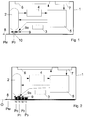
- the measuring device shown designed as a hand-held measuring device, comprises according to 1 shows an essentially cuboid housing 1, in or on which all other functional elements of the device are housed. These are in detail a movable measuring head 2, a drive device 3 for moving the measuring head 2, an optoelectric converter device 4, a computer 5, a display device 6 and controls in the form of a keyboard 7. Furthermore, the housing 1 with a Visor 8 provided, which for positioning the measuring device on a measurement object O serves. Below the measuring head 2 is a filter wheel that can move with it 9 provided, by means of which several different filters 9a selectively into the measuring beam path can be introduced.
- the measuring head 2 is in a rest position P 0 within the housing 1. If a measuring process is triggered, for example, by actuating an appropriate operating element, the measuring head 2 is moved out of the housing 1 into a measuring position P M by means of the drive device 3, in which it is located just above the visor 8. After completion of the measuring process, the measuring head 2 is pushed back into its rest position P 0 within the housing 1.
- the transducer device 4 is located with the measuring head 2 on a carriage, not shown, and is moved together with the measuring head.
- the measuring head 2 acts on one below it or below the visor 8 positioned measurement object O with a light source located in it Measuring light in a standardized angular range and catches that from the measuring object light remitted in a standardized angular range and transmits it to the converter device 4 further.
- the spectral composition of the measuring light and the collected Remitted light can be obtained by positioning one of the filters 9a of the filter wheel 9 influenced in the manner required for the selected type of measurement will. If desired, the positioning of the filters 9a can only be in the illumination beam path or only in the beam path, but only that Measuring light or only the reflected light would be affected.
- the collected light is analyzed spectrophotometrically, i.e.
- the essential difference according to the invention compared to the known measuring devices of this type is clear from the schematic representations of FIGS. 2 and 3.
- the measuring device according to the invention is equipped with a series of internal calibration measurement objects 10-13, which are arranged within the housing in corresponding calibration measurement positions P 0 -P 3 .
- one of these calibration measurement positions is at the same time the rest position of the measuring head, but need not be.
- the drive device 3 is designed such that, controlled by the computer 5, it can selectively move and position the measuring head 2 in each of these calibration measurement positions P 0 -P 3 .
- the computer 5 is designed or programmed so that it can trigger and carry out a measurement process in each of these calibration measurement positions P 0 -P 3 in the same way as in the measurement position P M.
- the calibration measurement objects 10-13 are arranged in the housing 1 such that they assume the same position relative to the measurement head located in the respective calibration measurement position as the measurement object O when the measurement head is in the measurement position P M.
- the internal calibration measurement objects arranged according to the invention in the housing 1 of the device 10-13 it can be different depending on the purpose Trade reference objects.
- a white standard is required for absolute white calibration
- Different color standards are required for checking the spectral calibration used.
- densitometric test tiles can also be used as calibration objects be used.
- the device can be designed, for example, to carry out an automatic absolute white calibration immediately before each normal measuring process. In this way, the instability of the light source in the measuring head can be corrected and the measurement values can thus be stabilized.
- the measuring process is triggered manually by the user, for example, the measuring head is initially still in the rest position P 0 above the Weiss standard 10.
- the computer 5 now initiates the measurement of the Weiss standard 10 and the automatic absolute white calibration.
- the measuring head 2 is then moved into the measuring position P M and the measurement object O is measured.
- the measuring head is then moved back to its rest position P 0 , the measurement results are calculated and displayed.
- the Weiss standard 10 is measured and the Calibration measurement values obtained in the process are stored together with the computer 5 Reference measured values in a manner known per se for automatic calibration of the device.
- the automatic calibration itself is done as already said, in a conventional manner and is not in itself the subject of the invention.
- the measurement of the Weiss standard can also be used for absolute white calibration through one or more of the filters 9a of the filter wheel 9. If the device is set correctly, e.g. before or shortly after delivery, they can do so obtained calibration measurement values also as reference measurement values for later use can be saved in the computer as described above.
- the measuring device is equipped with a corresponding operating mode.
- the setting and reliability of the measuring device is, e.g. the Weiss standard 10 to be measured by a so-called band glass provided in the filter wheel 9.
- a suitable band glass is e.g. the type BG 36 from Schott.
- the spectral remissions of the Weiss standard determined as calibration measured values and with the corresponding stored reference measured values are compared.
- a deviation value is used, e.g. as the square root of the sum the squares of the differences between the measured calibration measured values and the stored reference measured values is calculated.
- the deviation value is over a predetermined tolerance threshold, the computer 5 shows this in a suitable manner, e.g. by a corresponding alarm notification by means of the display device 6.
- the alarm notification can be made via the modern measuring devices this type of usual interface can be output to an external computer.
- the spectral calibration of the measuring device can also be based on the color standards Check 11-13.
- the color standards are measured spectrally and as Calibration measured values their respective color coordinates e.g. determined according to CIELAB.
- This Color coordinates are saved with the corresponding reference color coordinates the color standards compared and the respective color differences determined. If one or more of the color differences determined in this way above a preset tolerance threshold lies or lie, the computer 5 generates a corresponding alarm notification.
- This check can also be carried out at different positions of the filter wheel 9, so with different filters 9a.
- the filters 9a are otherwise the conventional Filters typically used in such measuring devices, for example UV cut filters, D65 filters, polarization filters and the like.
- a density step wedge (gray step wedge), which can be realized, for example, by calibration measurement objects in the form of a black, two gray and one white tile.
- the spectral remissions are measured over the visible spectral range and compared with corresponding stored reference values.
- the automatic calibration or verification of the measuring device can also be time or event controlled.
- the computer 5 be programmed to perform a check or calibration in certain time intervals or after a certain number of measurements carries out.
Landscapes
- Physics & Mathematics (AREA)
- Spectroscopy & Molecular Physics (AREA)
- General Physics & Mathematics (AREA)
- General Health & Medical Sciences (AREA)
- Analytical Chemistry (AREA)
- Biochemistry (AREA)
- Chemical & Material Sciences (AREA)
- Life Sciences & Earth Sciences (AREA)
- Immunology (AREA)
- Pathology (AREA)
- Health & Medical Sciences (AREA)
- Spectrometry And Color Measurement (AREA)
- Investigating Or Analysing Materials By Optical Means (AREA)
Abstract
Description
Die Erfindung betrifft eine Vorrichtung zur Messung von optischen Remissionswerten eines Messobjekts gemäss dem Oberbegriff des unabhängigen Anspruchs. Insbesondere betrifft die Erfindung ein Spektralphotometer.The invention relates to a device for measuring optical reflectance values a measurement object according to the preamble of the independent claim. Especially The invention relates to a spectrophotometer.
Typische Vertreter von Messvorrichtungen, insbesondere Spektralphotometern der gattungsgemässen Art sind beispielsweise in den US-Patentschriften US-A-4 968 140, US-A-4961 646 und US-A-4 929 084 (entsprechend EP-B-0 328 483, EP-B-0331 629 und EP-B-0 327 499) beschrieben. Diese rechnergesteuerten Messvorrichtungen sind als Handgeräte ausgebildet und weisen einen beweglichen Messkopf auf, der für den Messvorgang aus dem Gehäuse ausgefahren und anschliessend wieder in das Gehäuse zurückgezogen wird.Typical representatives of measuring devices, in particular spectrophotometers from of the generic type are described, for example, in US Pat. Nos. 4,968,140. US-A-4961 646 and US-A-4 929 084 (corresponding to EP-B-0 328 483, EP-B-0331 629 and EP-B-0 327 499). These computer-controlled measuring devices are designed as handheld devices and have a movable measuring head that is suitable for extend the measurement process from the housing and then back into the housing is withdrawn.
Wie viele Messgeräte müssen auch Messvorrichtungen der gattungsgemässen Art regelmässig kalibriert bzw. z.B. hinsichtlich ihrer spektralen Eichung überprüft werden, wenn die Zuverlässigkeit der Messresultate gewährleistet sein soll. Dies erfolgt in der Regel durch Ausmessen von speziellen, auf das jeweilige Messgerät abgestimmten Kalibriermessobjekten (Kalibrierstandards), die als separate Teile mit der Messvorrichtung geliefert werden. Die dabei ermittelten Messwerte werden durch den Rechner in Verbindung mit entsprechenden gespeicherten Referenzwerten ausgewertet, um entweder eine Aussage über die zu überprüfenden Eigenschaften der Messvorrichtung zu erhalten oder die Kalibration automatisch durchzuführen, sofern die Messvorrichtung mit solchen Funktionen ausgestattet ist.Like many measuring devices, measuring devices of the generic type also have to be used regularly calibrated or e.g. checked for their spectral calibration, if the reliability of the measurement results should be guaranteed. This takes place in the As a rule, by measuring special calibration objects that are tailored to the respective measuring device (Calibration standards), which are separate parts with the measuring device to be delivered. The measured values determined are saved by the computer in Association with corresponding stored reference values evaluated to either a statement about the properties of the measuring device to be checked received or perform the calibration automatically, provided the measuring device is equipped with such functions.
Diese Kalibrier- und Überprüfungsvorgänge bedürfen einer speziellen Sorgfalt und Regelmässigkeit. So müssen diese Vorgänge in den vorgeschriebenen Zeitintervallen durchgeführt werden, und die Positionierung der Messvorrichtung bzw. ihres Messkopfs relativ zum Kalibriermessobjekt muss korrekt sein, um die Messresultate nicht negativ zu beeinflussen.These calibration and verification processes require special care and Regularity. So these processes have to be in the prescribed time intervals be carried out, and the positioning of the measuring device or its measuring head relative to the calibration object must be correct in order not to the measurement results to affect negatively.
Durch die vorliegende Erfindung soll nun eine Messvorrichtung der gattungsgemässen Art dahingehend verbessert werden, dass die Kalibrierung und Überprüfung der Vorrichtung für den Benutzer einfacher und zuverlässiger wird. Insbesondere soll sich der Benutzer um die Kalibrierung und die Überprüfung überhaupt nicht kümmern müssen, d.h. diese Vorgänge sollen durch die Vorrichtung selbsttätig erfolgen.The present invention is now intended to be a measuring device of the generic type Kind of be improved in that the calibration and verification of the device becomes easier and more reliable for the user. In particular, the Users don't have to worry about calibration and verification at all, i.e. these processes are to be carried out automatically by the device.
Die Lösung dieser der Erfindung zugrundeliegenden Aufgabe ergibt sich aus den im
kennzeichnenden Teil des unabhängigen Anspruchs 1 beschriebenen Merkmalen. Besonders
vorteilhafte Ausgestaltungen und Weiterbildungen sind Gegenstand der abhängigen
Ansprüche 2-13.The solution to this problem underlying the invention results from the im
characterizing part of the
Die erfindungsgemässe Messvorrichtung enthält also mindestens ein Kalibriermessobjekt, welches fest in die Vorrichtung eingebaut ist und vom Messkopf angefahren werden kann. Beispielsweise kann das oder ein Kalibriermessobjekt in der Ruheposition des Messkopfs angeordnet sein. Auf diese Weise ist es möglich, das oder die Kalibriermessobjekte selbsttätig nach einem vorgegebenen Programm auszumessen und die entsprechenden Kalibrier- oder Überprüfungsvorgänge durchzuführen. Die Messung erfolgt dabei stets korrekt und in derselben Weise und kann nicht vergessen werden, und das oder die Kalibriermessobjekte sind stets verfügbar und können nicht mit zu anderen Messvorrichtungen gehörenden ähnlichen Kalibriermessobjekten verwechselt werden, wie dies bei herkömmlichen Messvorrichtungen mit separaten Kalibriermessobjekten in der Praxis häufig der Fall ist.The measuring device according to the invention thus contains at least one calibration measurement object, which is permanently installed in the device and is approached by the measuring head can. For example, the or a calibration measurement object in the rest position of the measuring head. In this way it is possible to use the calibration object or objects automatically measure according to a given program and the corresponding Perform calibration or verification operations. The measurement is done always correct and in the same way and can not be forgotten, and the calibration object or objects are always available and cannot be shared with others Similar calibration measurement objects belonging to measuring devices are confused, as with conventional measuring devices with separate calibration objects is often the case in practice.
Im folgenden wird die Erfindung anhand der Zeichnung näher erläutert. Es zeigen:
- Fig. 1
- eine Prinzipskizze eines Ausführungsbeispiels der erfindungsgemässen Vorrichtung,
- Fig. 2-3
- eine schematische Darstellung der Vorrichtung nach Fig. 1 mit dem Messkopf in Ruheposition und
- Fig. 3
- eine schematische Darstellung der Vorrichtung nach Fig. 1 mit dem Messkopf in Messposition.
- Fig. 1
- 2 shows a schematic diagram of an exemplary embodiment of the device according to the invention,
- Fig. 2-3
- a schematic representation of the device of FIG. 1 with the measuring head in the rest position and
- Fig. 3
- a schematic representation of the device of FIG. 1 with the measuring head in the measuring position.
Die dargestellte, als Handmessgerät ausgebildete Messvorrichtung umfasst gemäss
Fig.1 ein im wesentlichen quaderförmiges Gehäuse 1, in bzw. an welchem sämtliche
anderen Funktionselemente der Vorrichtung untergebracht sind. Im einzelnen sind dies
ein beweglicher Messkopf 2, eine Antriebsvorrichtung 3 zur Bewegung des Messkopfs
2, eine optoelektrische Wandlereinrichtung 4, ein Rechner 5, eine Anzeigevorrichtung
6 und Bedienungsorgane in Form einer Tastatur 7. Ferner ist das Gehäuse 1 mit einem
Visier 8 versehen, welches zur Positionierung der Messvorrichtung auf einem Messobjekt
O dient. Unterhalb des Messkopfs 2 ist ein mit diesem mitbewegliches Filterrad
9 vorgesehen, mittels welchem mehrere unterschiedliche Filter 9a selektiv in den Messstrahlengang
eingebracht werden können.The measuring device shown, designed as a hand-held measuring device, comprises according to
1 shows an essentially
Normalerweise befindet sich der Messkopf 2 in einer Ruheposition P0 innerhalb des
Gehäuses 1. Wenn ein Messvorgang z.B. durch Betätigen eines entsprechenden Bedienungsorgans
ausgelöst wird, wird der Messkopf 2 mittels der Antriebsvorrichtung 3
aus dem Gehäuse 1 in eine Messposition PM ausgefahren, in welcher er sich genau
oberhalb des Visiers 8 befindet. Nach Beendigung des Messvorgangs wird der Messkopf
2 wieder in seine Ruheposition P0 innerhalb des Gehäuses 1 zurückverschoben.
Die Wandlereinrichtung 4 befindet sich mit dem Messkopf 2 auf einem nicht gezeigten
Wagen und wird zusammen mit dem Messkopfbewegt.Normally, the
Beim Messvorgang beaufschlagt der Messkopf 2 ein unter ihm bzw. unterhalb des Visiers
8 positioniertes Messobjekt O mit aus einer in ihm befindlichen Lichtquelle stammenden
Messlicht in einem genormten Winkelbereich und fängt das vom Messobjekt
in einen genormten Winkelbereich remittierte Licht aufund leitet es an die Wandlereinrichtung
4 weiter. Die spektrale Zusammensetzung des Messlichts und des aufgefangenen
remittierten Lichts kann dabei durch Positionierung eines der Filter 9a des Filtetrads
9 in der für die gewählte Art der Messung erforderlichen Weise beeinflusst
werden. Die Positionierung der Filter 9a kann gewünschtenfalls auch nur im Beleuchtungsstrahlengang
oder nur im Auffangstrahlengang erfolgen, wobei eben nur das
Messlicht oder nur das remittierte Licht beeinflusst würde. In der Wandlereinrichtung
4 wird das aufgefangene Licht spektralphotometrisch analysiert, d.h. es werden die
Remissionen in z.B. 36 etwa 10 nm breiten Wellenlängenbereichen im sichtbaren Bereich
des Spektrums (380-730 nm) gemessen und in entsprechende elektrische Signale
umgewandelt. Diese Signale werden dann dem Rechner 5 zugeführt und von diesem
zur Bestimmung von für die jeweilige Messung interessierenden Messwerten, beispielsweise
Farbkoordinaten nach CIE, verarbeitet. Diese Messwerte werden dann auf
die Anzeigevorrichtung ausgegeben. Alle Messfunktionen und mechanischen Abläufe
der Vorrichtung werden vom Rechner 5 gesteuert.During the measuring process, the
Soweit entspricht die dargestellte Messvorrichtung in Aufbau und Funktion voll und ganz dem in den eingangs erwähnten US-Patentschriften US-A-4 968 140, US-A-4961 646 und US-A-4 929 084 im Detail beschriebenen Hand-Spektralphotometer, so dass der Fachmann keiner näheren Erläuterung bedarf. Die genannten US-Patentschriften werden hiermit ausdrücklich zum integrierenden Bestandteil der vorliegenden Erfindungsbeschreibung erklärt.So far, the measuring device shown corresponds fully in structure and function quite like that in the aforementioned U.S. Patents US-A-4,968,140, US-A-4,961 646 and US-A-4,929,084 handheld spectrophotometers described in detail so that the expert requires no further explanation. The aforementioned US patents hereby expressly become an integral part of the present description of the invention explained.
Der wesentliche, erfindungsgemässe Unterschied gegenüber den bekannten Messvorrichtungen
dieser Art wird aus den schematischen Darstellungen der Figuren 2 und 3
deutlich. Die erfindungsgemässe Messvorrichtung ist mit einer Reihe von internen Kalibriermessobjekten
10-13 ausgestattet, welche innerhalb des Gehäuses in entsprechenden
Kalibriermesspositionen P0-P3 angeordnet sind. Eine dieser Kalibriermesspositionen
ist im gezeigten Ausführungsbeispiel gleichzeitig die Ruheposition des Messkopfs,
muss sie aber nicht sein. Die Antriebsvorrichtung 3 ist so ausgebildet, dass sie, gesteuert
vom Rechner 5, den Messkopf 2 selektiv in jede dieser Kalibriermesspositionen P0-P3
verfahren und positionieren kann. Gleichzeitig ist der Rechner 5 so ausgebildet bzw.
programmiert, dass er in jeder dieser Kalibriermesspositionen P0-P3 gleich wie in der
Messposition PM einen Messvorgang auslösen und durchführen kann. Die Kalibriermessobjekte
10-13 sind im Gehäuse 1 so angeordnet, dass sie dieselbe Lage relativ
zum in der jeweiligen Kalibriermessposition befindlichen Messkopf einnehmen wie das
Messobjekt O, wenn sich der Messkopf in der Messposition PM befindet.The essential difference according to the invention compared to the known measuring devices of this type is clear from the schematic representations of FIGS. 2 and 3. The measuring device according to the invention is equipped with a series of internal calibration measurement objects 10-13, which are arranged within the housing in corresponding calibration measurement positions P 0 -P 3 . In the exemplary embodiment shown, one of these calibration measurement positions is at the same time the rest position of the measuring head, but need not be. The
Bei den erfindungsgemäss im Gehäuse 1 der Vorrichtung angeordneten internen Kalibriermessobjekten
10-13 kann es sich um je nach Bestimmungszweck unterschiedliche
Referenzobjekte handeln. Für eine Absolutweisskalibrierung ist ein Weiss-Standard
erforderlich, für die Überprüfung der spektralen Eichung werden verschiedene Farb-Standards
eingesetzt. Des weiteren können auch densitometrische Prüfkachel als Kalibriermessobjekte
verwendet werden. Mittels der erfindungsgemäss in das Gehäuse
eingebauten Kalibriermessobjekte ist es möglich, die für die verschiedenen Kalibrier- und
Überprüfungsvorgänge erforderlichen Messungen an den Kalibriermessobjekten
zeit-, ereignis- oder benutzergesteuert automatisch durchzuführen.In the case of the internal calibration measurement objects arranged according to the invention in the
Für das folgende wird beispielsweise davon ausgegangen, dass sich in der Ruheposition
und gleichzeitig Kalibrierposition P0 ein Weiss-Standard 10 für die Absolutweisskalibrierung
der Messvorrichtung und in den übrigen Kalibrierpositionen P1-P3 je ein
Farb-Standard 11-13 für die Überprüfung der spektralen Eichung der Messvorrichtung
befinden. Wenn nur die Absolutweisskalibrierung oder nur die Überprüfung der spektralen
Eichnung erforderlich ist, können die jeweils nicht erforderlichen Kalibriermessobjekte
selbstverständlich fehlen. Die Anordnung der einzelnen Kalibriermessobjekte
10-13 in den Kalibriermesspositionen P0-P3 kann selbstverständlich auch anders
gewählt sein. Ferner können für andere Arten von Überprüfungen auch andere Kalibriermessobjekte
vorgesehen sein.For the following, it is assumed, for example, that in the rest position and at the same time calibration position P 0 there is a
Die Vorrichtung kann durch entsprechende Programmierung des Rechners 5 beispielsweise
dazu ausgebildet sein, unmittelbar vor jedem normalen Messvorgang eine
automatische Absolutweisskalibrierung durchzuführen. Auf diese Weise lässt sich die
Unstabilität der Lichtquelle im Messkopf auskorrigieren und damit eine Stabilisierung
der Messwerte erreichen. Wenn der Messvorgang z.B. manuell durch den Benutzer
ausgelöst wird, befindet sich der Messkopf zunächst noch in der Ruheposition P0 über
dem Weiss-Standard 10. Der Rechner 5 veranlasst nun zunächst die Ausmessung des
Weiss-Standards 10 und die automatische Absolutweisskalibrierung. Danach wird der
Messkopf 2 in die Messposition PM ausgefahren und die Ausmessung des Messobjekts
O vorgenommen. Anschliessend wird der Messkopf wieder in seine Ruheposition P0
zurückgefahren, die Messresultate werden berechnet und angezeigt.By appropriate programming of the
Für die Absolutweisskalibrierung wird der Weiss-Standard 10 ausgemessen und die
dabei gewonnenen Kalibriermesswerte werden zusammen mit im Rechner 5 gespeicherten
Referenzmesswerten in an sich bekannter Weise zur automatischen Kalibrierung
der Vorrichtung herangezogen. Die automatische Kalibrierung selbst erfolgt, wie
schon gesagt, in herkömmlicher Weise und ist an sich nicht Gegenstand der Erfindung.For the absolute white calibration, the
Die Ausmessung des Weiss-Standards kann für die Absolutweisskalibrierung auch
durch eines oder mehrere der Filter 9a des Filterrads 9 erfolgen. Wenn die Vorrichtung
korrekt eingestellt ist, z.B. noch vor oder kurz nach der Auslieferung, können die dabei
gewonnenen Kalibriermesswerte auch als Referenzmesswerte für die spätere Verwendung
gemäss vorstehender Beschreibung im Rechner abgespeichert werden. Die
Messvorrichtung ist dazu mit einem entsprechenden Betriebsmodus ausgestattet.The measurement of the Weiss standard can also be used for absolute white calibration
through one or more of the
Eine Möglichkeit zur Überprüfung der spektralen Eichung und damit der korrekten
Einstellung und Zuverlässigkeit der Messvorrichtung besteht darin, z.B. den Weiss-Standard
10 durch ein im Filterrad 9 vorgesehenes sog. Bandenglas zu messen. Ein
geeignetes Bandenglas ist z.B. der Typ BG 36 der Firma Schott. Hierbei werden die
spektralen Remissionen des Weiss-Standards als Kalibriermesswerte bestimmt und mit
den entsprechenden gespeicherten Referenzmesswerten verglichen. Als Qualitätskriterium
wird ein Abweichungswert verwendet, der z.B. als Quadratwurzel aus der Summe
der Quadrate der Differenzen zwischen den gemessenen Kalibriermesswerten und
den gespeicherten Referenzmesswerten berechnet wird. Ist der Abweichungswert über
einer vorgegebenen Toleranzschwelle, so zeigt der Rechner 5 dies in geeigneter Weise,
z.B. durch einen entsprechenden Alarm-Hinweis mittels der Anzeigevorrichtung 6 an.
Alternativ oder zusätzlich kann der Alarm-Hinweis über die bei modernen Messvorrichtungen
dieser Art übliche Schnittstelle an einen externen Rechner ausgegeben werden.A possibility to check the spectral calibration and thus the correct one
The setting and reliability of the measuring device is, e.g. the Weiss standard
10 to be measured by a so-called band glass provided in the
Die spektrale Eichung der Messvorrichtung lässt sich auch anhand der Farb-Standards
11-13 überprüfen. Hierzu werden die Farb-Standards spektral ausgemessen und als
Kalibriermesswerte ihre jeweiligen Farbkoordinaten z.B. nach CIELAB bestimmt. Diese
Farbkoordinaten werden mit den entsprechenden gespeicherten Referenz-Farbkoordinaten
der Farb-Standards verglichen und die jeweiligen Farbabstände ermittelt. Wenn
einer oder mehrere der so ermittelten Farbabstände über einer voreingestellten Toleranzschwelle
liegt bzw. liegen, erzeugt der Rechner 5 einen entsprechenden Alarm-Hinweis.
Auch diese Überprüfung kann bei verschiedenen Stellungen des Filterrads 9,
also mit verschiedenen Filtern 9a erfolgen. Die Filter 9a sind im übrigen die herkömmlichen,
bei solchen Messvorrichtungen üblicherweise eingesetzten Filter, beispielsweise
UV-Cut-Filter, D65-Filter, Polarisations-Filter und dergleichen.The spectral calibration of the measuring device can also be based on the color standards
Check 11-13. For this purpose, the color standards are measured spectrally and as
Calibration measured values their respective color coordinates e.g. determined according to CIELAB. This
Color coordinates are saved with the corresponding reference color coordinates
the color standards compared and the respective color differences determined. If
one or more of the color differences determined in this way above a preset tolerance threshold
lies or lie, the
Ebenfalls möglich ist die Überprüfung der Linearität des Messsystems der Vorrichtung
durch Ausmessen eines Dichtestufenkeils (Graustufenkeils), der z.B. durch Kalibriermessobjekte
in Form einer schwarzen, zweier grauer und einer weissen Kachel realisiert
sein kann. Für jede der (hier beispielsweise vier) Kacheln (Kalibriermessobjekte)
des Graustufenkeils werden die spektralen Remissionen über den sichtbaren Spektralbereich
gemessen und mit entsprechenden gespeicherten Referenzwerten verglichen.
Als Qualitätsmass wird für jeden Wellenlängenbereich j ein Wert Kj nach der Formel:
![]()
![]()
![]()
![]()
Wie schon erwähnt, kann die automatische Kalibrierung oder Überprüfung der Messvorrichtung
auch zeit- oder ereignisgesteuert erfolgen. So kann der Rechner 5 beispielsweise
so programmiert sein, dass er eine Überprüfung oder Kalibrierung in bestimmten
zeitlichen Intervallen oder jeweils nach einer bestimmten Anzahl von Messungen
durchführt.As already mentioned, the automatic calibration or verification of the measuring device
can also be time or event controlled. For example, the
Claims (15)
Priority Applications (5)
| Application Number | Priority Date | Filing Date | Title |
|---|---|---|---|
| EP97107780A EP0878704B1 (en) | 1997-05-13 | 1997-05-13 | Reflectance measurement apparatus |
| DE59712476T DE59712476D1 (en) | 1997-05-13 | 1997-05-13 | Remission measurement device |
| CA002231958A CA2231958A1 (en) | 1997-05-13 | 1998-04-22 | Reflectance measuring device |
| US09/075,202 US5982501A (en) | 1997-05-13 | 1998-05-11 | Reflectance measuring device |
| JP10130539A JPH10318913A (en) | 1997-05-13 | 1998-05-13 | Reflectance-measuring apparatus |
Applications Claiming Priority (1)
| Application Number | Priority Date | Filing Date | Title |
|---|---|---|---|
| EP97107780A EP0878704B1 (en) | 1997-05-13 | 1997-05-13 | Reflectance measurement apparatus |
Publications (2)
| Publication Number | Publication Date |
|---|---|
| EP0878704A1 true EP0878704A1 (en) | 1998-11-18 |
| EP0878704B1 EP0878704B1 (en) | 2005-11-09 |
Family
ID=8226790
Family Applications (1)
| Application Number | Title | Priority Date | Filing Date |
|---|---|---|---|
| EP97107780A Expired - Lifetime EP0878704B1 (en) | 1997-05-13 | 1997-05-13 | Reflectance measurement apparatus |
Country Status (5)
| Country | Link |
|---|---|
| US (1) | US5982501A (en) |
| EP (1) | EP0878704B1 (en) |
| JP (1) | JPH10318913A (en) |
| CA (1) | CA2231958A1 (en) |
| DE (1) | DE59712476D1 (en) |
Cited By (11)
| Publication number | Priority date | Publication date | Assignee | Title |
|---|---|---|---|---|
| EP1092972A1 (en) * | 1999-10-11 | 2001-04-18 | Gretag-Macbeth AG | Apparatus for automatic measurements on measuring fields |
| WO2009021745A1 (en) * | 2007-08-16 | 2009-02-19 | Giesecke & Devrient Gmbh | Device and method for calibrating a sensor system |
| EP2368667A1 (en) * | 2010-03-26 | 2011-09-28 | Hommel-Etamic GMBH | Measuring device |
| EP2270450B1 (en) * | 2009-06-24 | 2011-10-12 | X-Rite Europe GmbH | Handheld light measuring device |
| US8336224B2 (en) | 2009-09-22 | 2012-12-25 | Hommel-Etamic Gmbh | Measuring device |
| US8725446B2 (en) | 2009-07-08 | 2014-05-13 | Hommel-Etamic Gmbh | Method for determining the shape of a workpiece |
| US9393663B2 (en) | 2010-08-23 | 2016-07-19 | Hommel-Etamic Gmbh | Measuring device |
| DE102004021448B4 (en) * | 2004-04-30 | 2016-12-29 | Carl Zeiss Spectroscopy Gmbh | Spectrometric reflection probe and method for its internal recalibration |
| US9562756B2 (en) | 2012-09-20 | 2017-02-07 | Jenoptik Industrial Metrology Germany Gmbh | Measuring device with calibration |
| EP2176642B1 (en) * | 2007-08-16 | 2018-08-01 | Giesecke+Devrient Currency Technology GmbH | Method for calibrating a sensor system |
| DE102004021601B4 (en) * | 2004-05-03 | 2020-10-22 | Heidelberger Druckmaschinen Ag | Inline measurement and control for printing machines |
Families Citing this family (23)
| Publication number | Priority date | Publication date | Assignee | Title |
|---|---|---|---|---|
| US6385552B1 (en) * | 1999-08-10 | 2002-05-07 | Tyco Telecommunications (Us) Inc. | Method for collecting test measurements |
| ES2510615T3 (en) | 2000-03-31 | 2014-10-21 | Cosmetic Technologies Llc | Nail polish color selection procedure |
| US6597454B1 (en) * | 2000-05-12 | 2003-07-22 | X-Rite, Incorporated | Color measurement instrument capable of obtaining simultaneous polarized and nonpolarized data |
| JP4054853B2 (en) * | 2000-10-17 | 2008-03-05 | 独立行政法人農業・食品産業技術総合研究機構 | Blood analysis using near infrared spectroscopy |
| US8636173B2 (en) | 2001-06-01 | 2014-01-28 | Cosmetic Technologies, L.L.C. | Point-of-sale body powder dispensing system |
| US6615881B2 (en) | 2001-09-24 | 2003-09-09 | Imx Labs, Inc. | Apparatus and method for custom cosmetic dispensing |
| US8573263B2 (en) | 2001-09-24 | 2013-11-05 | Cosmetic Technologies, Llc | Apparatus and method for custom cosmetic dispensing |
| DE60218708D1 (en) | 2001-09-24 | 2007-04-19 | Cosmetic Technologies Llc | DEVICE AND METHOD FOR INDIVIDUAL COMPOSITION OF COSMETICS |
| DE102004048102A1 (en) * | 2004-04-30 | 2006-04-20 | Carl Zeiss Jena Gmbh | Spectrometric measuring head and method for its recalibration |
| WO2006020189A2 (en) | 2004-07-19 | 2006-02-23 | Barthomolew Julie R | Customized retail point of sale dispensing methods |
| JP4699473B2 (en) | 2004-11-08 | 2011-06-08 | アール. バーソロミュー ジュリー | Customized cosmetic automatic blending equipment |
| JP2006153498A (en) * | 2004-11-25 | 2006-06-15 | Konica Minolta Sensing Inc | Standard surface sample and optical characteristic measuring system |
| EP2087341B1 (en) * | 2006-11-20 | 2012-04-11 | Pioneer-Hi-Bred International, Inc. | System and method for measuring a harvest quality parameter on a harvesting device |
| US8395638B2 (en) * | 2007-11-29 | 2013-03-12 | Datacolor Holding Ag | Method and apparatus for calibrating a display-coupled color measuring device |
| US8717567B2 (en) * | 2011-08-31 | 2014-05-06 | Datacolor Holding Ag | Method and apparatus for calibrating a color measurement device |
| US9459206B2 (en) * | 2012-05-02 | 2016-10-04 | Datacolor Holding Ag | System and apparatus for measurement of light scattering from a sample |
| CN104280122B (en) | 2013-07-08 | 2019-02-22 | 美泰有限公司 | Colorimeter calibration system and method |
| EP3302169B1 (en) | 2015-06-08 | 2021-07-21 | Cosmetic Technologies, LLC | Automated delivery system of a cosmetic sample |
| JP6506120B2 (en) * | 2015-06-30 | 2019-04-24 | 旭化成エレクトロニクス株式会社 | Gas sensor |
| US20190049306A1 (en) * | 2017-08-10 | 2019-02-14 | Westco Scientific Instruments, Inc | Calibration for baking contrast units |
| DE102018133152A1 (en) * | 2018-12-20 | 2020-06-25 | Endress+Hauser Conducta Gmbh+Co. Kg | Procedure for calibrating a spectrometer |
| CN110763657B (en) * | 2019-11-20 | 2022-05-13 | 江苏赛诺格兰医疗科技有限公司 | Photoelectric digital conversion system for reflective material reflectivity test system |
| CN111855595B (en) * | 2020-08-24 | 2022-04-05 | 四川长虹电器股份有限公司 | Spectral data calibration method based on black and white calibration plate |
Citations (4)
| Publication number | Priority date | Publication date | Assignee | Title |
|---|---|---|---|---|
| EP0331629A1 (en) * | 1988-02-02 | 1989-09-06 | GRETAG Aktiengesellschaft | Hand-held device for measuring photometric data |
| EP0383209A1 (en) * | 1989-02-10 | 1990-08-22 | X-Rite, Inc. | Automated strip reader densitometer |
| WO1992015859A1 (en) * | 1991-02-27 | 1992-09-17 | Boehringer Mannheim Corporation | Apparatus and method for analyzing body fluids |
| WO1996042010A1 (en) * | 1995-06-12 | 1996-12-27 | Measurex Corporation | Color sensor simulating standard source illuminant |
Family Cites Families (2)
| Publication number | Priority date | Publication date | Assignee | Title |
|---|---|---|---|---|
| EP0327499B1 (en) * | 1988-02-02 | 1992-01-08 | GRETAG Aktiengesellschaft | Measuring head |
| DE58900675D1 (en) * | 1988-02-02 | 1992-02-20 | Gretag Ag | HAND DEVICE FOR DETECTING PHOTOMETRIC DATA. |
-
1997
- 1997-05-13 DE DE59712476T patent/DE59712476D1/en not_active Expired - Lifetime
- 1997-05-13 EP EP97107780A patent/EP0878704B1/en not_active Expired - Lifetime
-
1998
- 1998-04-22 CA CA002231958A patent/CA2231958A1/en not_active Abandoned
- 1998-05-11 US US09/075,202 patent/US5982501A/en not_active Expired - Lifetime
- 1998-05-13 JP JP10130539A patent/JPH10318913A/en active Pending
Patent Citations (4)
| Publication number | Priority date | Publication date | Assignee | Title |
|---|---|---|---|---|
| EP0331629A1 (en) * | 1988-02-02 | 1989-09-06 | GRETAG Aktiengesellschaft | Hand-held device for measuring photometric data |
| EP0383209A1 (en) * | 1989-02-10 | 1990-08-22 | X-Rite, Inc. | Automated strip reader densitometer |
| WO1992015859A1 (en) * | 1991-02-27 | 1992-09-17 | Boehringer Mannheim Corporation | Apparatus and method for analyzing body fluids |
| WO1996042010A1 (en) * | 1995-06-12 | 1996-12-27 | Measurex Corporation | Color sensor simulating standard source illuminant |
Cited By (15)
| Publication number | Priority date | Publication date | Assignee | Title |
|---|---|---|---|---|
| EP1092972A1 (en) * | 1999-10-11 | 2001-04-18 | Gretag-Macbeth AG | Apparatus for automatic measurements on measuring fields |
| EP1291645A1 (en) * | 1999-10-11 | 2003-03-12 | Gretag-Macbeth AG | Apparatus for automatic measurement of test fields |
| US6732917B1 (en) | 1999-10-11 | 2004-05-11 | Gretag-Macbeth Ag | Apparatus for automatic measurement of measuring fields |
| DE102004021448B4 (en) * | 2004-04-30 | 2016-12-29 | Carl Zeiss Spectroscopy Gmbh | Spectrometric reflection probe and method for its internal recalibration |
| DE102004021601B4 (en) * | 2004-05-03 | 2020-10-22 | Heidelberger Druckmaschinen Ag | Inline measurement and control for printing machines |
| US8304713B2 (en) | 2007-08-16 | 2012-11-06 | Giesecke & Devrient Gmbh | Device and method for calibrating a sensor system |
| EP2176642B1 (en) * | 2007-08-16 | 2018-08-01 | Giesecke+Devrient Currency Technology GmbH | Method for calibrating a sensor system |
| WO2009021745A1 (en) * | 2007-08-16 | 2009-02-19 | Giesecke & Devrient Gmbh | Device and method for calibrating a sensor system |
| EP2270450B1 (en) * | 2009-06-24 | 2011-10-12 | X-Rite Europe GmbH | Handheld light measuring device |
| US8725446B2 (en) | 2009-07-08 | 2014-05-13 | Hommel-Etamic Gmbh | Method for determining the shape of a workpiece |
| US8336224B2 (en) | 2009-09-22 | 2012-12-25 | Hommel-Etamic Gmbh | Measuring device |
| US8429829B2 (en) | 2010-03-26 | 2013-04-30 | Hommel-Etamic Gmbh | Measuring device |
| EP2368667A1 (en) * | 2010-03-26 | 2011-09-28 | Hommel-Etamic GMBH | Measuring device |
| US9393663B2 (en) | 2010-08-23 | 2016-07-19 | Hommel-Etamic Gmbh | Measuring device |
| US9562756B2 (en) | 2012-09-20 | 2017-02-07 | Jenoptik Industrial Metrology Germany Gmbh | Measuring device with calibration |
Also Published As
| Publication number | Publication date |
|---|---|
| EP0878704B1 (en) | 2005-11-09 |
| US5982501A (en) | 1999-11-09 |
| JPH10318913A (en) | 1998-12-04 |
| DE59712476D1 (en) | 2005-12-15 |
| CA2231958A1 (en) | 1998-11-13 |
Similar Documents
| Publication | Publication Date | Title |
|---|---|---|
| EP0878704B1 (en) | Reflectance measurement apparatus | |
| DE4434168B4 (en) | Device and method for measuring and evaluating spectral radiation and in particular for measuring and evaluating color properties | |
| DE2902776C2 (en) | ||
| DE3034544C2 (en) | ||
| DE102007053574B4 (en) | colorimeter | |
| DE10341327A1 (en) | Photoelectric sensor combines detected value of deflected light with desired light adjustment value, by adjusting light-reception transformation rate and light-transmission power, after adjustment instruction execution | |
| EP0174496B1 (en) | Procedure for measuring the radiation wavelength and the wavelength-corrected radiation power of monochromatical light-sources and arrangement for carrying out this procedure | |
| DE112011103113T5 (en) | Reflectivity measuring device, reflectivity measuring method, membrane thickness measuring device and membrane thickness measuring method | |
| DE3886308T2 (en) | Spectrophotometer. | |
| WO2010124866A1 (en) | Method and device for carrying out an optical comparison between at least two samples, preferably by comparing sections that can be selected | |
| DE3037771C2 (en) | ||
| EP0812415B1 (en) | Method for producing comparability of spectrometer measurements | |
| DE2546253A1 (en) | Spectral analyzer and colorimeter photo: receiver - has several light sensitive receivers with differing spectral sensitivities covered with block filter(s) | |
| EP1650589B1 (en) | Microscope having a device for recognition of optical components | |
| DE19646236C2 (en) | Device for endoscopic diagnosis and treatment of tissue | |
| DE102012107319B4 (en) | Passive measuring system | |
| DE3401475C2 (en) | ||
| EP1600761A1 (en) | Tabletting press with integrated NIR measurement device | |
| DE2701777C2 (en) | Arrangement for recording the injection time and for determining the jet cross-section generated by injection nozzles on injection valves | |
| EP1379845A2 (en) | Device for the simultaneous detection of radiation of different wavelength | |
| EP0123672A2 (en) | Method for the determination of the mass of absorbing parts in a sample, and device for carrying out said method | |
| EP3078950A1 (en) | Colour measuring method and colour measuring device | |
| DE3915692C2 (en) | ||
| DE102008063464A1 (en) | Recognition of scattered light effect on registering an intensity, e.g. in spectrometry, has a reference channel with barrier band and band pass filters | |
| DE3844651C2 (en) |
Legal Events
| Date | Code | Title | Description |
|---|---|---|---|
| PUAI | Public reference made under article 153(3) epc to a published international application that has entered the european phase |
Free format text: ORIGINAL CODE: 0009012 |
|
| AK | Designated contracting states |
Kind code of ref document: A1 Designated state(s): CH DE FR GB IT LI |
|
| 17P | Request for examination filed |
Effective date: 19990507 |
|
| AKX | Designation fees paid |
Free format text: CH DE FR GB IT LI |
|
| GRAP | Despatch of communication of intention to grant a patent |
Free format text: ORIGINAL CODE: EPIDOSNIGR1 |
|
| GRAS | Grant fee paid |
Free format text: ORIGINAL CODE: EPIDOSNIGR3 |
|
| GRAA | (expected) grant |
Free format text: ORIGINAL CODE: 0009210 |
|
| AK | Designated contracting states |
Kind code of ref document: B1 Designated state(s): CH DE FR GB IT LI |
|
| REG | Reference to a national code |
Ref country code: GB Ref legal event code: FG4D Free format text: NOT ENGLISH |
|
| REG | Reference to a national code |
Ref country code: CH Ref legal event code: EP |
|
| REF | Corresponds to: |
Ref document number: 59712476 Country of ref document: DE Date of ref document: 20051215 Kind code of ref document: P |
|
| GBT | Gb: translation of ep patent filed (gb section 77(6)(a)/1977) |
Effective date: 20060123 |
|
| ET | Fr: translation filed | ||
| PLBE | No opposition filed within time limit |
Free format text: ORIGINAL CODE: 0009261 |
|
| STAA | Information on the status of an ep patent application or granted ep patent |
Free format text: STATUS: NO OPPOSITION FILED WITHIN TIME LIMIT |
|
| 26N | No opposition filed |
Effective date: 20060810 |
|
| PGFP | Annual fee paid to national office [announced via postgrant information from national office to epo] |
Ref country code: IT Payment date: 20080524 Year of fee payment: 12 |
|
| REG | Reference to a national code |
Ref country code: CH Ref legal event code: PFA Owner name: X-RITE EUROPE GMBH Free format text: GRETAG-MACBETH AG#ALTHARDSTRASSE 70#8105 REGENSDORF (CH) -TRANSFER TO- X-RITE EUROPE GMBH#ALTHARDSTRASSE 70#8105 REGENSDORF (CH) |
|
| REG | Reference to a national code |
Ref country code: FR Ref legal event code: ST Effective date: 20100129 |
|
| PG25 | Lapsed in a contracting state [announced via postgrant information from national office to epo] |
Ref country code: FR Free format text: LAPSE BECAUSE OF NON-PAYMENT OF DUE FEES Effective date: 20090602 |
|
| PGFP | Annual fee paid to national office [announced via postgrant information from national office to epo] |
Ref country code: FR Payment date: 20080526 Year of fee payment: 12 |
|
| PG25 | Lapsed in a contracting state [announced via postgrant information from national office to epo] |
Ref country code: IT Free format text: LAPSE BECAUSE OF NON-PAYMENT OF DUE FEES Effective date: 20090513 |
|
| REG | Reference to a national code |
Ref country code: DE Ref legal event code: R082 Ref document number: 59712476 Country of ref document: DE Representative=s name: SCHWABE SANDMAIR MARX PATENTANWAELTE RECHTSANW, DE Ref country code: DE Ref legal event code: R082 Ref document number: 59712476 Country of ref document: DE Representative=s name: SCHWABE SANDMAIR MARX, DE Ref country code: DE Ref legal event code: R081 Ref document number: 59712476 Country of ref document: DE Owner name: X-RITE SWITZERLAND GMBH, CH Free format text: FORMER OWNER: X-RITE EUROPE GMBH, REGENSDORF, CH |
|
| REG | Reference to a national code |
Ref country code: CH Ref legal event code: PFA Owner name: X-RITE SWITZERLAND GMBH, CH Free format text: FORMER OWNER: X-RITE EUROPE GMBH, CH |
|
| PGFP | Annual fee paid to national office [announced via postgrant information from national office to epo] |
Ref country code: GB Payment date: 20160520 Year of fee payment: 20 Ref country code: CH Payment date: 20160519 Year of fee payment: 20 Ref country code: DE Payment date: 20160520 Year of fee payment: 20 |
|
| REG | Reference to a national code |
Ref country code: DE Ref legal event code: R071 Ref document number: 59712476 Country of ref document: DE |
|
| REG | Reference to a national code |
Ref country code: CH Ref legal event code: PL |
|
| REG | Reference to a national code |
Ref country code: GB Ref legal event code: PE20 Expiry date: 20170512 |
|
| PG25 | Lapsed in a contracting state [announced via postgrant information from national office to epo] |
Ref country code: GB Free format text: LAPSE BECAUSE OF EXPIRATION OF PROTECTION Effective date: 20170512 |