EP0878345B1 - Hinge fitting for automotive vehicle seats and seat provided with such an articulation - Google Patents
Hinge fitting for automotive vehicle seats and seat provided with such an articulation Download PDFInfo
- Publication number
- EP0878345B1 EP0878345B1 EP98401105A EP98401105A EP0878345B1 EP 0878345 B1 EP0878345 B1 EP 0878345B1 EP 98401105 A EP98401105 A EP 98401105A EP 98401105 A EP98401105 A EP 98401105A EP 0878345 B1 EP0878345 B1 EP 0878345B1
- Authority
- EP
- European Patent Office
- Prior art keywords
- flange
- coupling
- support flange
- lever
- seat
- Prior art date
- Legal status (The legal status is an assumption and is not a legal conclusion. Google has not performed a legal analysis and makes no representation as to the accuracy of the status listed.)
- Expired - Lifetime
Links
Images


Classifications
-
- B—PERFORMING OPERATIONS; TRANSPORTING
- B60—VEHICLES IN GENERAL
- B60N—SEATS SPECIALLY ADAPTED FOR VEHICLES; VEHICLE PASSENGER ACCOMMODATION NOT OTHERWISE PROVIDED FOR
- B60N2/00—Seats specially adapted for vehicles; Arrangement or mounting of seats in vehicles
- B60N2/02—Seats specially adapted for vehicles; Arrangement or mounting of seats in vehicles the seat or part thereof being movable, e.g. adjustable
- B60N2/22—Seats specially adapted for vehicles; Arrangement or mounting of seats in vehicles the seat or part thereof being movable, e.g. adjustable the back-rest being adjustable
- B60N2/235—Seats specially adapted for vehicles; Arrangement or mounting of seats in vehicles the seat or part thereof being movable, e.g. adjustable the back-rest being adjustable by gear-pawl type mechanisms
- B60N2/2356—Seats specially adapted for vehicles; Arrangement or mounting of seats in vehicles the seat or part thereof being movable, e.g. adjustable the back-rest being adjustable by gear-pawl type mechanisms with internal pawls
- B60N2/2358—Seats specially adapted for vehicles; Arrangement or mounting of seats in vehicles the seat or part thereof being movable, e.g. adjustable the back-rest being adjustable by gear-pawl type mechanisms with internal pawls and provided with memory locks
Definitions
- the present invention relates to a joint for a seat, in particular for a motor vehicle, and a seat provided with this articulation.
- FR-A-2 722 150 describes a articulation of this type, for a motor vehicle seat, in which the coupling lever is placed in position securing the connecting flange by means of a operating cam cooperating by wedge effect with a jamming cam follower in the lever.
- the invention aims to avoid decoupling accidental joint flanges in the event of an impact violent.
- the subject of the invention is a joint for a seat, in particular for a motor vehicle, of the aforementioned type, characterized in that it further comprises means for blocking the second end of the lever in the securing position activated only when the flanges are coupled together and undergo a torque tending to accidentally decouple them.
- the invention also relates to a seat for motor vehicle provided with at least one articulation such as defined above.
- FIG. 1 shows a seat S for motor vehicle with a D file connected to a seat A by two joints 20 according to the invention.
- the joints 20 are of the same type as that described in FR-A-2 722 150 concerning a so-called "memory" joint.
- This type of joint allows in particular to fold the seat back on the seat of the latter, for example to access a place at the back of this seat, and raise the backrest position of use, without changing the setting of the inclination of the backrest.
- Each articulation 20 is the symmetrical specular of the other joint.
- the joints 20 are preferably controlled by a handle 22 common to these two joints.
- hinge 20 has two flanges of connection 24,26 of generally circular shape, one, fixed, being fixed on the seat A, and the other, mobile, being fixed on file D.
- connection flanges 24, 26 are mounted to rotate one relative to the other around an axis of articulation X which is substantially perpendicular to them, and are held against each other in a manner known per se at by means of a connecting ring 28.
- the connecting flanges 24,26 are centered one relative to each other by peripheral shoulders complementary E1, E2, coaxial with the axis of articulation X.
- the connecting flanges 24, 26 delimit between them a housing for means 30 for coupling these flanges.
- These means 30 are controlled by a shaped member 32 general circular cylindrical, to which is fixed in a manner known per se the control handle 22.
- the control member 32 is rotatably mounted around of the articulation axis X in two bearings P1, P2, arranged in the connecting flanges 24,26.
- the control member 32 is movable, by through the handle 22, in two directions opposite to from a rest position, i.e. clockwise from adjustment of the inclination of the backrest relative to the seat and an anti-clockwise direction of folding of this backrest.
- the control members 32 of the two joints 20 are interconnected by a coupling device classic.
- the coupling means 30 comprise four levers 34a to 34d, preferably identical, shaped general arc, extending substantially parallel to the connecting flanges 24.26.
- a first end 36A of the coupling levers 34a to 34d is pivotally mounted on a support flange 38 of generally circular shape, housed between the flanges of link 24.26 so that it can rotate relative to the latter around the axis of articulation X.
- the flanges 24,26 and the support flange 38 are substantially parallel to each other.
- the second end 36B of the levers 34a to 34d is intended to be subjected to a connecting flange correspondent, through cooperation of complementary forms defining, when engaged, an area securing the coupling lever.
- Each coupling lever 34a to 34b is therefore movable around its pivot axis between a securing position of its second end 36B with a corresponding connecting flange 34a to 34b and a position for releasing this second end 36B.
- Coupling levers 34a to 34d are associated in pairs at the connecting flanges 24.26.
- the two levers of the same pair are substantially symmetrical with respect to to the articulation axis X and are articulated on the same side 38A, 38B of the support flange, so that the four levers 34a to 34d alternate on the two faces 38A, 38D of the support flange.
- These levers 34a to 34d are articulated on sectors 40a to 40d of the support flange offset in alternating parallel to the axis of articulation X.
- support flange 38 can be subject, by coupling with one and / or the other of connecting flanges 24,26 by means of levers 34a to 34d, to seat and / or seat back.
- the complementary forms of subjugation are preferably delimited by complementary teeth.
- the second end 36B of the coupling levers 34a to 34d has a toothed sector 42a to 42d.
- toothed sectors 42a, 42b of the pair of levers coupling 34a, 34b associated with the fixed flange 24 are intended to cooperate with toothed sectors 44a, 44b of same angle formed on the inside contour of a shoulder peripheral 46 of this fixed flange 24, visible in particular in Figures 3 and 4.
- the toothed sectors 42c, 42d of the pair of levers coupling 34c, 34d associated with the movable flange 26 are intended to cooperate with a toothed sector 48 of angle upper formed on the inside contour of a shoulder peripheral 50 of the movable flange 26, visible in particular on Figure 5.
- this toothed sector 48 extends over the entire circumference of the shoulder 50 so as to form a toothed crown.
- the first end 36A of the coupling levers 34a to 34b carries a pivot pin P, formed for example by a semi-cutout of this end 36A, pivotally mounted in a pivoting light L arranged in the sector corresponding 40a to 40d of the support flange 38.
- the pawn P and light L materialize a lever pivot axis coupling substantially parallel to the axis of rotation X.
- the pawn P and the tilting light L have by example of the general shapes in half-moons, the light L extending along a sector larger than that of the pawn P.
- each coupling lever 34a to 34d can tilt around a fulcrum (materialized by the light L for tilting this lever) which, when lever is subject to a connecting flange 24,26, is fixed with respect to this same flange.
- the control unit 32 actuates means of operation of the coupling levers 34a to 34 d. These means of maneuver to place the levers in a rest configuration, as shown in the Figures 4 and 5, in which the two connecting flanges 24.26 are coupled together, and in two configurations alternative active ingredients, only one of which is shown on the Figure 6, in which the two connecting flanges 24,26 are decoupled.
- levers coupling 34a to 34d are all subject to the flanges of link 24,26, to couple these and immobilize the backrest in relation to the seat.
- the operating means include two rings rotary 52,54 centered on the hinge axis X, by example by means of two pairs of circular arcs C1, C2, delimiting a central opening of the support flange 38, cooperating with the outer contours of the rings. Bows centering C1, C2 of the same pair delimit two sectors diametrically opposed 40c, 40d, 40a, 40b of the support flange 38.
- each ring 52.54 can be moved in two directions opposites for tilt adjustment and folding folder respectively.
- each ring 52.54 is associated with a pair of coupling levers 34a to 34d, of so as to be movable between a first position to subject the levers of this pair to the flange of 24.26 corresponding link and a second position of release of these levers.
- each ring 52.54 includes a pair of cams operation 56a to 56d, diametrically opposite, delimited by bosses formed on the external contour of the Ring.
- each actuating cam 56a to 56d cooperates with a wedging cam 58a to 58d, delimited by a boss formed on the internal contour of a coupling lever 34a to 34d corresponding, close to the second end 36B of this lever.
- each cam operation 56a to 56d cooperates with a cam follower of tilting 60a to 60d, delimited by a boss provided on the internal contour of a coupling lever 34a to 34d corresponding, near the first end 36A of this lever.
- each ring 52.54 is limited by the angular dimension of a clearance 62.64, formed in a centering arc C1, C2 corresponding, in which extends a tab 66,68 secured to the outer contour of the ring 52.54.
- the rings 52.54 each include a lug of displacement 70.72 formed on their internal contour.
- the control member 32 is provided with a cam 74 of displacement of the rings 52, 54, interposed between the two lugs 70.72.
- Displacement cam 74 cooperates selectively with the two pins 70,72, which thus form displacement cams, by rotation in directions opposite tilt adjustment and tilting folder respectively.
- control member 32 When the maneuvering means are in the rest configuration, the control member 32 is in the rest position as shown in FIGS. 4 and 5, to which it is elastically recalled by means which will be described below.
- the elastic return means comprise approximate positioning means of the control member.
- These approximate positioning means include a spring 76 with angular effect hooked on the pins 70.74 so as to resiliently recall the rings 52.54 in opposite directions, towards their position of subjugation, i.e. their position of cooperation of the operating cams 56a to 56d with the jamming cams 58a to 58c.
- the spring 76 recalls the control member 32 in the approached rest position by cooperation of the two lugs 70,72 with the displacement cam 74 of this member control.
- the spring 76 is constituted for example by a split ring whose axial edges are hooked in the lugs 70.72.
- each ring 52, 54 has a boss 78.80 formed on its internal contour, on the other side of its lug 70.72 relative to the cam 74 of the control member, so that participate in the positioning and centering of the spring 76 to angular effect.
- the elastic return means include also means for precise positioning of the organ control 32 refining the approximate rest position of this member 32, represented in FIGS. 3,7 and 8.
- These precise positioning means include at minus a thrust spring 82, in the form of a blade folded in U, comprising two flat branches 84,86 extending substantially longitudinally parallel to the axis of articulation X.
- a first branch 84, fixed is in radial support against the fixed flange 24, more particularly against the edge of a clearance 88 of the contour of the bearing P1 of the flange fixed 24.
- the second branch 86 is in radial support against a flat 90 for positioning the command 32.
- the thrust spring 82 biases the flat 90 in a position substantially parallel to that of its branches 84.86 coinciding with the precise rest position of the control member 32.
- the flat 90 is delimited by a substantially concave surface, so as to limit the contact of the movable branch 86 with this flat 90 substantially two generators of the control member 32.
- the free end of the movable branch 86 comprises two hooking lugs 92.94, substantially perpendicular to the axis of articulation X. These legs 92.94 are intended to axially immobilize the spring of thrust 82 and, for this purpose, are interposed between the face internal of the fixed flange 24 and a shoulder 96 of the organ shown in Figure 3.
- the hanging lugs 92.94 extend transversely to the control member 32, on both sides other than the latter, and are preferably housed in a recess 98 from the internal face of the fixed flange 24 compensating for the thickness of these legs.
- the joint may have two thrust springs 82, cooperating with two flats 90, arranged diametrically opposite in the flange fixed 24.
- thrust spring allowing it to be placed in radial support between the edge of clearance 88 and the flat of positioning 90 so as to solicit the latter in a position coinciding with the precise rest position of the control unit.
- the articulation 20 also includes means for blocking of the second end 36B of the coupling levers 34a to 34d in the securing position.
- the blocking means comprise, for each coupling lever 34a to 34d, two complementary ramps blocking device 100,102 respectively provided on the support flange 38 and on the second end 36B of the lever coupling, and on the other hand, a weakening zone of the support flange 38.
- Each locking ramp 100 carried by the support flange 38 is provided on a sector 40a to 40d of this support flange adjacent to a sector 40a to 40d on which is articulated the lever 34a to 34d, carrying the ramp of additional blocking 102.
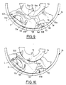
- blocking ramps 100,102 are spaced apart, as is shown in Figures 4,5 and 9.
- the weakening zone of the support flange 38 associated with a corresponding coupling lever 34a to 34d, preferably comprises a portion 104 of this support flange 38 extending between the pivoting light L and a weakening light 106 formed in the support flange 38, close to the pivoting light L and between the latter and the blocking ramp 100 carried by the support flange 38.
- the dimming light 106 may have various shapes, for example oblong (as is shown in particular in Figure 9) or circular.
- the curved interior contour of the coupling levers 34a to 34d has a notch 108 weakening of these levers allowing, when the flanges of the joint undergo an accidental torque, a deformation of these levers by modification of their curvature. This change in curvature makes it easier to cooperation of the locking ramps 100.102.
- the joint 20 is particularly well adapted to withstand accidental torque when the connecting flanges 24,26 are coupled between them.
- this couple deforms the weakened areas of the support flange 38 so as to make the ramps cooperate blocking 100,102 and strengthening the subjection of the levers coupling 34a to 34d to the connection flanges 24.26 correspondents.
- the joint 20 according to the invention is not necessarily an articulation of the memory type and can be provided, for example, for perform only the tilt adjustment function of the folder without the switch function of the latter.
- the support flange is constituted by the fixed connection flange, the joint not comprising than a pair of coupling levers, or even a single lever of coupling.
Description
La présente invention concerne une articulation pour siège, notamment pour véhicule automobile, et un siège muni de cette articulation.The present invention relates to a joint for a seat, in particular for a motor vehicle, and a seat provided with this articulation.
On connaít déjà dans l'état de la technique une articulation pour siège, notamment pour véhicule automobile, du type comprenant
- au moins un flasque de liaison, destiné à être fixé à une assise ou un dossier du siège, et un flasque-support pouvant être assujetti à l'assise et/ou au dossier, les flasques étant montés rotatifs l'un par rapport à l'autre autour d'un axe d'articulation qui leur est sensiblement perpendiculaire, et
- au moins un levier de couplage des flasques entre eux muni d'une première extrémité montée pivotante sur le flasque-support, autour d'un axe de pivotement sensiblement parallèle à l'axe d'articulation, de manière que le levier de couplage puisse pivoter entre, d'une part, une position d'assujettissement d'une seconde extrémité de ce levier au flasque de liaison, par coopération de formes complémentaires, et d'autre part, une position de libération de cette seconde extrémité.
- at least one connecting flange, intended to be fixed to a seat or a backrest of the seat, and a support flange that can be secured to the seat and / or the backrest, the flanges being rotatably mounted relative to the other around an axis of articulation which is substantially perpendicular to them, and
- at least one coupling lever for the flanges between them provided with a first end pivotally mounted on the support flange, about a pivot axis substantially parallel to the articulation axis, so that the coupling lever can pivot between, on the one hand, a position for securing a second end of this lever to the connecting flange, by cooperation of complementary shapes, and on the other hand, a position for releasing this second end.
FR-A-2 722 150 décrit une articulation de ce type, pour siège de véhicule automobile, dans laquelle le levier de couplage est placé en position d'assujettissement du flasque de liaison au moyen d'une came de manoeuvre coopérant par effet de coin avec une contre-came de coincement ménagée dans le levier.FR-A-2 722 150 describes a articulation of this type, for a motor vehicle seat, in which the coupling lever is placed in position securing the connecting flange by means of a operating cam cooperating by wedge effect with a jamming cam follower in the lever.
En cas de choc subi par le véhicule conduisant à un effort longitudinal violent exercé sur le dossier du siège, les flasques de l'articulation subissent un couple important pouvant les découpler accidentellement.In the event of an impact to the vehicle leading to a violent longitudinal force exerted on the back of the seat, the flanges of the joint undergo a torque important that can accidentally decouple them.
Ceci se produit notamment lorsque le couple accidentel s'exerce à l'encontre de l'effet de coin qui maintient en contact les cames de manoeuvre et de coincement. This occurs especially when the couple accidental is exerted against the wedge effect which keeps in contact the actuating and jamming.
L'invention a pour but d'éviter le découplage accidentel des flasques de l'articulation en cas de choc violent.The invention aims to avoid decoupling accidental joint flanges in the event of an impact violent.
A cet effet, l'invention a pour objet une articulation pour siège, notamment pour véhicule automobile, du type précité, caractérisée en ce qu'elle comprend de plus des moyens de blocage de la seconde extrémité du levier en position d'assujettissement activés uniquement lorsque les flasques sont couplés entre eux et subissent un couple tendant à les découpler accidentellement.To this end, the subject of the invention is a joint for a seat, in particular for a motor vehicle, of the aforementioned type, characterized in that it further comprises means for blocking the second end of the lever in the securing position activated only when the flanges are coupled together and undergo a torque tending to accidentally decouple them.
Suivant d'autres caractéristiques de cette articulation :
- les moyens de blocage comprennent
- deux rampes complémentaires de blocage portées respectivement par le flasque-support et par la seconde extrémité du levier de couplage, ces rampes étant écartées entre elles lorsque le levier de couplage est en position d'assujettissement, et
- une zone d'affaiblissement du flasque-support déformable lorsque les flasques subissent le couple accidentel, de manière à permettre le déplacement relatif du levier de couplage par rapport au flasque-support jusqu'à mise en contact des rampes de blocage qui coopèrent pour bloquer la seconde extrémité du levier de couplage en position d'assujettissement au flasque de liaison ;
- l'axe de pivotement du levier de couplage est matérialisé par un pion de pivotement, porté par la première extrémité de ce levier, pivotant dans une lumière de pivotement ménagée dans le flasque-support, et la zone d'affaiblissement comporte une portion du flasque-support s'étendant entre la lumière de pivotement et une lumière d'affaiblissement qui est ménagée dans le flasque-support à proximité de la lumière de pivotement et entre cette lumière de pivotement et la rampe de blocage portée par le flasque-support ;
- le levier de couplage a une forme générale en arc, le contour intérieur de ce levier comportant une échancrure d'affaiblissement de ce levier permettant, lorsque les rampes de blocage coopèrent par effet du couple accidentel, une déformation du levier de couplage par modification de sa courbure ;
- l'articulation comporte un autre flasque de liaison avec le dossier ou l'assise et au moins un autre levier de couplage du flasque-support avec cet autre flasque de liaison, le flasque-support étant logé entre les deux flasques de liaison, les deux leviers de couplage étant articulés respectivement sur deux faces opposées du flasque-support ;
- les deux flasques de liaison sont destinés à être fixés respectivement à l'assise et au dossier du siège, l'articulation comprenant de plus, des moyens de manoeuvre des leviers de couplage entre une configuration de repos dans laquelle les leviers de couplage sont tous assujettis à leur flasque de liaison correspondant, pour coupler ces derniers et immobiliser le dossier par rapport à l'assise, et deux configurations actives alternatives dans laquelle un seul des leviers de couplage est assujetti à son flasque de liaison correspondant pour permettre, selon le cas, le réglage de l'inclinaison ou le rabattement temporaire du dossier;
- l'articulation comprend une paire de leviers de couplage associés à chaque flasque de liaison et disposés sensiblement symétriquement par rapport à l'axe d'articulation, les quatre leviers de couplage étant articulés en alternance sur les deux faces du flasque-support et sur des secteurs de ce flasque-support décalés parallèlement à l'axe d'articulation, chaque rampe de blocage portée par le flasque-support étant ménagée sur un secteur de ce flasque-support adjacent à un secteur sur lequel est articulé le levier de couplage portant la rampe de blocage complémentaire.
- the blocking means include
- two complementary locking ramps carried respectively by the support flange and by the second end of the coupling lever, these ramps being spaced apart when the coupling lever is in the securing position, and
- a weakening zone of the deformable support flange when the flanges undergo the accidental torque, so as to allow the relative displacement of the coupling lever relative to the support flange until contacting of the locking ramps which cooperate to block the second end of the coupling lever in position for securing to the connecting flange;
- the pivot axis of the coupling lever is materialized by a pivot pin, carried by the first end of this lever, pivoting in a pivoting opening in the support flange, and the weakening zone includes a portion of the flange -support extending between the pivoting light and a weakening light which is formed in the support flange near the pivoting light and between this pivoting light and the blocking ramp carried by the support flange;
- the coupling lever has a generally arcuate shape, the internal contour of this lever comprising a weakening notch of this lever allowing, when the locking ramps cooperate by effect of the accidental torque, a deformation of the coupling lever by modification of its curvature;
- the articulation comprises another connection flange with the backrest or the seat and at least one other lever for coupling the support flange with this other connection flange, the support flange being housed between the two connection flanges, the two coupling levers being articulated respectively on two opposite faces of the support flange;
- the two connecting flanges are intended to be fixed respectively to the seat and to the seat back, the articulation further comprising means for operating the coupling levers between a rest configuration in which the coupling levers are all subject to their corresponding connection flange, to couple them and immobilize the backrest with respect to the seat, and two alternative active configurations in which only one of the coupling levers is subject to its corresponding connection flange to allow, as the case may be, adjusting the inclination or temporary folding of the backrest;
- the articulation comprises a pair of coupling levers associated with each connecting flange and arranged substantially symmetrically with respect to the articulation axis, the four coupling levers being articulated alternately on the two faces of the support flange and on sectors of this support flange offset parallel to the articulation axis, each blocking ramp carried by the support flange being provided on a sector of this support flange adjacent to a sector on which the coupling lever carrying the additional blocking ramp.
L'invention a également pour objet un siège pour véhicule automobile muni d'au moins une articulation telle que définie ci-dessus.The invention also relates to a seat for motor vehicle provided with at least one articulation such as defined above.
L'invention sera mieux comprise à la lecture de la description qui va suivre donnée uniquement à titre d'exemple et faite en se référant aux dessins dans lesquels:
- la figure 1 est une vue schématique en perspective d'un siège pour véhicule automobile muni d'au moins une articulation selon l'invention ;
- la figure 2 est une vue en perspective de cette articulation ;
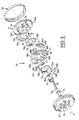
- la figure 3 est une vue éclatée de l'articulation représentée à la figure 2 ;
- les figures 4 et 5 sont des vues de face,
respectivement suivant les
flèches 4 et 5, de l'articulation représentée à la figure 2, avec un arrachement du flasque de liaison pointé par lesflèches 4 et 5 donnant accès visuellement à l'intérieur de l'articulation, les leviers de couplages étant dans leur position d'assujettissement aux flasques de liaison; - la figure 6 est une vue similaire à la figure 4 dans laquelle les leviers de couplage sont dans leur position de libération de leur flasque de liaison correspondant;
- les figures 7 et 8 sont des vues suivant la
flèche 7 de la figure 3 montrant un organe de commande de l'articulation dans deux positions différentes respectivement ; - les figures 9 et 10 sont des demi-vues similaires à la figure 5, à échelle agrandie, montrant l'articulation respectivement avant et après avoir subi un couple accidentel.
- Figure 1 is a schematic perspective view of a seat for a motor vehicle provided with at least one articulation according to the invention;
- Figure 2 is a perspective view of this joint;
- Figure 3 is an exploded view of the joint shown in Figure 2;
- Figures 4 and 5 are front views, respectively along
arrows arrows - Figure 6 is a view similar to Figure 4 wherein the coupling levers are in their release position of their corresponding connecting flange;
- Figures 7 and 8 are views along
arrow 7 of Figure 3 showing a member for controlling the joint in two different positions respectively; - Figures 9 and 10 are half-views similar to Figure 5, on an enlarged scale, showing the joint respectively before and after having suffered an accidental torque.
On a représenté sur la figure 1 un siège S pour
véhicule automobile comportant un dossier D relié à une
assise A par deux articulations 20 selon l'invention.FIG. 1 shows a seat S for
motor vehicle with a D file connected to a
seat A by two
Les articulations 20 sont du même type que celui
décrit dans FR-A-2 722 150 concernant une
articulation dite "à mémoire". Ce type d'articulation
permet notamment de rabattre le dossier du siège sur
l'assise de ce dernier, par exemple pour accéder à une
place à l'arrière de ce siège, et de relever le dossier en
position d'utilisation, ceci sans modifier le réglage de
l'inclinaison du dossier.The
Chaque articulation 20 est la symétrique
spéculaire de l'autre articulation.Each
Les articulations 20 sont commandées de préférence
par une poignée 22 commune à ces deux articulations.The
En se référant notamment aux figures 2 et 3, sur
lesquelles on a représenté une articulation 20 plus en
détail, on voit que celle-ci comporte deux flasques de
liaison 24,26 de forme générale circulaire, l'un, fixe,
étant fixé sur l'assise A, et l'autre, mobile, étant fixé
sur le dossier D.With particular reference to Figures 2 and 3, on
which have been shown a
Les flasques de liaison 24,26 sont montés rotatifs
l'un par rapport à l'autre autour d'un axe d'articulation X
qui leur est sensiblement perpendiculaire, et sont
maintenus l'un contre l'autre de façon connue en soi au
moyen d'une bague de liaison 28.The
Les flasques de liaison 24,26 sont centrés l'un
par rapport à l'autre par des épaulements périphériques
complémentaires E1,E2, coaxiaux à l'axe d'articulation X.The connecting
Les flasques de liaison 24,26 délimitent entre eux
un logement pour des moyens 30 de couplage de ces flasques.
Ces moyens 30 sont commandés par un organe 32 de forme
générale cylindrique circulaire, sur lequel est fixée de
façon connue en soi la poignée de commande 22. The connecting
L'organe de commande 32 est monté rotatif autour
de l'axe d'articulation X dans deux paliers P1,P2, ménagés
dans les flasques de liaison 24,26.The
L'organe de commande 32 est déplaçable, par
l'intermédiaire de la poignée 22, dans deux sens opposés à
partir d'une position de repos, à savoir un sens horaire de
réglage de l'inclinaison du dossier par rapport à l'assise
et un sens anti-horaire de rabattement de ce dossier.The
Les organes de commande 32 des deux articulations
20 sont reliés entre eux par un dispositif de couplage
classique.The
Les moyens de couplage 30 comprennent quatre
leviers 34a à 34d, de préférence identiques, en forme
générale d'arc, s'étendant sensiblement parallèlement aux
flasques de liaison 24,26.The coupling means 30 comprise four
Une première extrémité 36A des leviers de couplage
34a à 34d est montée pivotante sur un flasque support 38 de
forme générale circulaire, logé entre les flasques de
liaison 24,26 de manière à pouvoir tourner par rapport à
ces derniers autour de l'axe d'articulation X. Les flasques
de liaison 24,26 et le flasque support 38 sont sensiblement
parallèles entre eux.A
La seconde extrémité 36B des leviers 34a à 34d est
destinée à être assujettie à un flasque de liaison
correspondant, par coopération de formes complémentaires
définissant, lorsqu'elles sont en prise, une zone
d'assujettissement du levier de couplage.The
Chaque levier de couplage 34a à 34b est donc
déplaçable autour de son axe de pivotement entre une
position d'assujettissement de sa seconde extrémité 36B
avec un flasque de liaison 34a à 34b correspondant et une
position de libération de cette seconde extrémité 36B.Each
Les leviers de couplage 34a à 34d sont associés
par paires aux flasques de liaison 24,26. Les deux leviers
d'une même paire sont sensiblement symétriques par rapport
à l'axe d'articulation X et sont articulés sur une même
face 38A,38B du flasque-support, de manière que les quatre
leviers 34a à 34d alternent sur les deux faces 38A,38D du
flasque-support. Ces leviers 34a à 34d sont articulés sur
des secteurs 40a à 40d du flasque-support décalés en
alternance parallèlement à l'axe d'articulation X.Coupling levers 34a to 34d are associated
in pairs at the connecting flanges 24.26. The two levers
of the same pair are substantially symmetrical with respect to
to the articulation axis X and are articulated on the
On notera que le flasque-support 38 peut être
assujetti, par couplage avec l'un et/ou l'autre des
flasques de liaison 24,26 au moyen des leviers 34a à 34d, à
l'assise et/ou au dossier du siège.Note that the
Les formes complémentaires d'assujettissement sont
délimitées de préférence par des dentures complémentaires.
Ainsi, la seconde extrémité 36B des leviers de couplage 34a
à 34d comporte un secteur denté 42a à 42d.The complementary forms of subjugation are
preferably delimited by complementary teeth.
Thus, the
Les secteurs dentés 42a,42b de la paire de leviers
de couplage 34a,34b associés au flasque fixe 24 sont
destinés à coopérer avec des secteurs dentés 44a,44b de
même angle ménagés sur le contour intérieur d'un épaulement
périphérique 46 de ce flasque fixe 24, visible notamment
sur les figures 3 et 4.The
Les secteurs dentés 42c,42d de la paire de leviers
de couplage 34c,34d associés au flasque mobile 26 sont
destinés à coopérer avec un secteur denté 48 d'angle
supérieur ménagé sur le contour intérieur d'un épaulement
périphérique 50 du flasque mobile 26, visible notamment sur
la figure 5. De préférence, ce secteur denté 48 s'étend sur
toute la circonférence de l'épaulement 50 de manière à
former une couronne dentée.The
La première extrémité 36A des leviers de couplage
34a à 34b porte un pion de pivotement P, formé par exemple
par une semi-découpe de cette extrémité 36A, monté pivotant
dans une lumière de pivotement L ménagée dans le secteur
correspondant 40a à 40d du flasque-support 38. Le pion P et
la lumière L matérialisent un axe de pivotement de levier
de couplage sensiblement parallèle à l'axe de rotation X.The
Le pion P et la lumière L de basculement ont par exemple des formes générales en demi-lunes, la lumière L s'étendant suivant un secteur plus grand que celui du pion P.The pawn P and the tilting light L have by example of the general shapes in half-moons, the light L extending along a sector larger than that of the pawn P.
On notera que chaque levier de couplage 34a à 34d
peut basculer autour d'un point d'appui (matérialisé par la
lumière L de basculement de ce levier) qui, lorsque ce
levier est assujetti à un flasque de liaison 24,26, est
fixe par rapport à ce même flasque.Note that each
L'organe de commande 32 actionne des moyens de
manoeuvre des leviers de couplage 34a à 34 d. Ces moyens de
manoeuvre permettent de placer les leviers dans une
configuration de repos, telle que représentée sur les
figures 4 et 5, dans laquelle les deux flasques de liaison
24,26 sont couplés entre eux, et dans deux configurations
actives alternatives, dont une seule est représentée sur la
figure 6, dans laquelle les deux flasques de liaison 24,26
sont découplés.The
Le fonctionnement normal d'une articulation à
mémoire du type illustré sur les figures, pour le réglage
de l'inclinaison et le rabattement du dossier est
classique. Ce fonctionnement est décrit, par exemple, dans
FR-A-2 722 150 dans lequel, notamment, les
pênes 53 et grains 43 sont analogues aux leviers 34a à 34d
décrits ci-dessus.The normal functioning of a joint at
memory of the type illustrated in the figures, for setting
of the inclination and the folding of the backrest is
classic. This operation is described, for example, in
FR-A-2 722 150 in which, in particular, the
bolts 53 and grains 43 are similar to
Dans la configuration de repos, les leviers de
couplage 34a à 34d sont tous assujettis aux flasques de
liaison 24,26, pour coupler ces derniers et immobiliser le
dossier par rapport à l'assise.In the rest configuration, the levers
coupling 34a to 34d are all subject to the flanges of
Dans les deux configurations actives alternatives,
une seule des paires de leviers de couplage 34a à 34d est
assujettie au flasque de liaison 24,26 correspondant pour
permettre, alternativement, le réglage de l'inclinaison du
dossier ou, comme dans le cas représenté à la figure 6, le
rabattement temporaire de ce dossier.In the two alternative active configurations,
only one of the pairs of
Les moyens de manoeuvre comprennent deux bagues
rotatives 52,54 centrées sur l'axe d'articulation X, par
exemple au moyen de deux paires d'arcs circulaires C1,C2,
délimitant une ouverture centrale du flasque-support 38,
coopérant avec les contours externes des bagues. Les arcs
de centrage C1,C2 d'une même paire délimitent deux secteurs
diamétralement opposés 40c,40d,40a,40b du flasque-support
38.The operating means include two rings
rotary 52,54 centered on the hinge axis X, by
example by means of two pairs of circular arcs C1, C2,
delimiting a central opening of the
Les bagues 52,54 sont déplaçables dans deux sens
opposés pour le réglage d'inclinaison et le rabattement du
dossier respectivement. A cet effet, chaque bague 52,54 est
associée à une paire de leviers de couplage 34a à 34d, de
manière à être déplaçable entre une première position
d'assujettissement des leviers de cette paire au flasque de
liaison 24,26 correspondant et une seconde position de
libération de ces leviers.The
En se référant notamment aux figures 4 à 6, on
voit que chaque bague 52,54 comprend une paire de cames de
manoeuvre 56a à 56d, diamétralement opposées, délimitées
par des bossages ménagés sur le contour externe de la
bague.With particular reference to Figures 4 to 6, we
see that each ring 52.54 includes a pair of
Lorsqu'une bague 52,54 est dans sa première
position d'assujettissement, comme cela est représenté sur
les figures 4 et 5, chaque came de manoeuvre 56a à 56d
coopère avec une contre-came de coincement 58a à 58d,
délimitée par un bossage ménagé sur le contour interne d'un
levier de couplage 34a à 34d correspondant, à proximité de
la seconde extrémité 36B de ce levier.When a 52.54 ring is in its first
securing position, as shown in
Figures 4 and 5, each
Lorsqu'une bague 52,54 est dans sa seconde
position de libération, comme cela est représenté sur la
figure 6 (dans le cas de la bague 52), chaque came de
manoeuvre 56a à 56d coopère avec une contre-came de
basculement 60a à 60d, délimitée par un bossage ménagé sur
le contour interne d'un levier de couplage 34a à 34d
correspondant, à proximité de la première extrémité 36A de
ce levier.When a 52.54 ring is in its second
release position, as shown in the
Figure 6 (in the case of the ring 52), each
On notera que le déplacement angulaire de chaque
bague 52,54 est limité par la dimension angulaire d'un
dégagement 62,64, ménagé dans un arc de centrage C1,C2
correspondant, dans lequel s'étend un onglet 66,68
solidaire du contour externe de la bague 52,54.Note that the angular displacement of each
ring 52.54 is limited by the angular dimension of a
clearance 62.64, formed in a centering arc C1, C2
corresponding, in which extends a
Les bagues 52,54 comprennent chacune un ergot de déplacement 70,72 ménagé sur leur contour interne.The rings 52.54 each include a lug of displacement 70.72 formed on their internal contour.
L'organe de commande 32 est muni d'une came 74 de
déplacement des bagues 52,54, interposée entre les deux
ergots 70,72. La came de déplacement 74 coopère
sélectivement avec les deux ergots 70,72, qui forment ainsi
des contre-cames de déplacement, par rotation dans des sens
opposés de réglage d'inclinaison et de rabattement du
dossier respectivement.The
Lorsque les moyens de manoeuvre sont dans la
configuration de repos, l'organe de commande 32 est dans la
position de repos telle que représentée aux figures 4 et 5,
vers laquelle il est rappelé élastiquement par des moyens
qui seront décrits ci-dessous.When the maneuvering means are in the
rest configuration, the
Les moyens de rappel élastique comprennent des moyens de positionnement approché de l'organe de commande.The elastic return means comprise approximate positioning means of the control member.
Ces moyens de positionnement approché comportent
un ressort 76 à effet angulaire accroché sur les ergots
70,74 de manière à rappeler élastiquement les bagues 52,54
dans des sens opposés, vers leur position
d'assujettissement, c'est-à-dire leur position de
coopération des cames de manoeuvre 56a à 56d avec les
contre-cames de coincement 58a à 58c.These approximate positioning means include
a
Ainsi, le ressort 76 rappelle l'organe de commande
32 en position de repos approchée par coopération des deux
ergots 70,72 avec la came de déplacement 74 de cet organe
de commande.Thus, the
Le ressort 76 est constitué par exemple par un
anneau fendu dont les bords axiaux sont accrochés dans les
ergots 70,72.The
De préférence, chaque bague 52,54 comporte un
bossage 78,80 ménagé sur son contour interne, de l'autre
côté de son ergot 70,72 par rapport à la came
d'entraínement 74 de l'organe de commande, de manière à
participer au positionnement et au centrage du ressort 76 à
effet angulaire.Preferably, each
Les moyens de rappel élastique comprennent
également des moyens de positionnement précis de l'organe
de commande 32 affinant la position de repos approchée de
cet organe 32, représentés sur les figures 3,7 et 8.The elastic return means include
also means for precise positioning of the
Ces moyens de positionnement précis comprennent au
moins un ressort de poussée 82, en forme de lame pliée en
U, comportant deux branches planes 84,86 s'étendant
sensiblement longitudinalement parallèlement à l'axe
d'articulation X.These precise positioning means include at
minus a
Une première branche 84, fixe, est en appui radial
contre le flasque fixe 24, plus particulièrement contre le
bord d'un dégagement 88 du contour du palier P1 du flasque
fixe 24.A
La seconde branche 86, mobile, est en appui radial
contre un méplat 90 de positionnement de l'organe de
commande 32.The
Le ressort de poussée 82 sollicite le méplat 90
dans une position sensiblement parallèle à celle de ses
branches 84,86 coïncidant avec la position de repos précise
de l'organe de commande 32.The
De préférence, le méplat 90 est délimité par une
surface sensiblement concave, de manière à limiter le
contact de la branche mobile 86 avec ce méplat 90
sensiblement à deux génératrices de l'organe de commande
32.Preferably, the flat 90 is delimited by a
substantially concave surface, so as to limit the
contact of the
L'extrémité libre de la branche mobile 86 comporte
deux pattes d'accrochage 92,94, sensiblement
perpendiculaires à l'axe d'articulation X. Ces pattes 92,94
sont destinées à immobiliser axialement le ressort de
poussée 82 et, à cet effet, sont interposées entre la face
interne du flasque fixe 24 et un épaulement 96 de l'organe
de commande, visible sur la figure 3.The free end of the
Les pattes d'accrochage 92,94 s'étendent
transversalement à l'organe de commande 32, de part et
d'autre de ce dernier, et sont logées, de préférence, dans
un décrochement 98 de la face interne du flasque fixe 24
compensant l'épaisseur de ces pattes.The hanging lugs 92.94 extend
transversely to the
En variante, l'articulation peut comporter deux
ressorts de poussée 82, coopérant avec deux méplats 90,
agencés de façon diamétralement opposée dans le flasque
fixe 24.Alternatively, the joint may have two
thrust
Bien entendu, on peut envisager d'autres formes du
ressort de poussée permettant de le placer en appui radial
entre le bord du dégagement 88 et le méplat de
positionnement 90 de manière à solliciter ce dernier dans
une position coïncidant avec la position de repos précise
de l'organe de commande.Of course, we can consider other forms of
thrust spring allowing it to be placed in radial support
between the edge of
Le fonctionnement des moyens de rappel élastique
de l'organe de commande 32 se déduit clairement de leur
description ci-dessus.The functioning of the elastic return means
of the
En particulier, on notera que lorsqu'on fait
tourner l'organe de commande 32 de sa position de repos
vers une position active de déplacement d'une des bagues
52,54, comme cela est représenté sur la figure 6, le
ressort 76 à effet angulaire se déforme par augmentation de
son diamètre. Le ressort 76 s'appuie par un de ses bords
axiaux sur l'ergot 70,72 de la bague 52,54 qui reste fixe
en renforçant ainsi l'assujettissement au flasque de
liaison correspondant des leviers de couplage associés à
cette bague.In particular, it will be noted that when we do
turn the
De même, lorsqu'on fait tourner l'organe de
commande 32 dans un sens ou dans l'autre, à partir de sa
position de repos, le ressort de poussée 82 se déforme
élastiquement par rapprochement de ces branches 84,86, de
manière à permettre la rotation de cet organe de commande
32 dans le palier P1, comme cela est représenté sur la
figure 8.Similarly, when we rotate the
L'articulation 20 comporte également des moyens de
blocage de la seconde extrémité 36B des leviers de couplage
34a à 34d en position d'assujettissement. The
Ces moyens de blocage sont activés uniquement
lorsque les flasques de liaison 24,26 et le flasque-support
38 sont couplés entre eux, c'est-à-dire lorsque l'organe de
commande 32 est en position de repos, et lorsque ces
flasques 24,26,38 subissent un couple tendant à les
découpler accidentellement.These blocking means are activated only
when the connecting
En se référant notamment aux figures 9 et 10, on
voit que les moyens de blocage comprennent, pour chaque
levier de couplage 34a à 34d, deux rampes complémentaires
de blocage 100,102 ménagées respectivement sur le flasque-support
38 et sur la seconde extrémité 36B du levier de
couplage, et d'autre part, une zone d'affaiblissement du
flasque-support 38.With particular reference to Figures 9 and 10, we
sees that the blocking means comprise, for each
Chaque rampe de blocage 100 portée par le flasque-support
38 est ménagée sur un secteur 40a à 40d de ce
flasque-support adjacent à un secteur 40a à 40d sur lequel
est articulé le levier 34a à 34d, portant la rampe de
blocage complémentaire 102.Each
Lorsqu'un levier de couplage 34a à 34d est en
position d'assujettissement, les rampes de blocage 100,102
correspondantes sont écartées entre elles, comme cela est
représenté sur les figures 4,5 et 9.When a
La zone d'affaiblissement du flasque-support 38,
associée à un levier de couplage 34a à 34d correspondant,
comporte de préférence une portion 104 de ce flasque-support
38 s'étendant entre la lumière de pivotement L et
une lumière d'affaiblissement 106 ménagée dans le flasque-support
38, à proximité de la lumière de pivotement L et
entre cette dernière et la rampe de blocage 100 portée par
le flasque-support 38.The weakening zone of the
La lumière d'affaiblissement 106 peut avoir diverses formes, par exemple oblongue (comme cela est représenté notamment sur la figure 9) ou circulaire.The dimming light 106 may have various shapes, for example oblong (as is shown in particular in Figure 9) or circular.
La zone d'affaiblissement du flasque-support,
associée à chaque levier de couplage 34a à 34d, se déforme
lorsque les flasques de l'articulation subissent un couple
accidentel, de manière à permettre le déplacement relatif
du levier de couplage par rapport au flasque-support 38
jusqu'à mise en contact des rampes de blocage 100,102,
comme cela est représenté sur la figure 10. Ces rampes
100,102 coopèrent alors pour bloquer la seconde extrémité
36B du levier de couplage en position d'assujettissement
dans laquelle les dentures de ce levier sont en prise avec
celles du flasque de liaison correspondant.The weakening zone of the support flange,
associated with each
De préférence, le contour intérieur courbe des
leviers de couplage 34a à 34d comporte une échancrure 108
d'affaiblissement de ces leviers permettant, lorsque les
flasques de l'articulation subissent un couple accidentel,
une déformation de ces leviers par modification de leur
courbure. Cette modification de courbure facilite la
coopération des rampes de blocage 100,102.Preferably, the curved interior contour of the
coupling levers 34a to 34d has a
L'articulation 20 est particulièrement bien
adaptée pour résister à un couple subit accidentellement
lorsque les flasques de liaison 24,26 sont couplés entre
eux.The joint 20 is particularly well
adapted to withstand accidental torque
when the connecting
En effet, si le couple accidentel est appliqué
dans le sens du coincement des cames de manoeuvre 56a à 56d
avec les contre-cames de coincement 58a à 58d,
l'assujettissement des leviers de couplage 34a à 34d aux
flasques de liaison 24,26 correspondants est renforcé, ce
qui empêche le découplage accidentel de ces flasques de
liaison.Indeed, if the accidental torque is applied
in the direction of jamming of the
Si le couple accidentel est appliqué à l'encontre
de l'effet de coincement entre les cames de manoeuvre 56a à
56d et les contre-cames de coincement 58a à 58d (c'est-à-dire
si le couple accidentel est appliqué dans un sens
d'écartement de l'axe de pivotement des leviers de couplage
34a à 34d et de la zone d'assujettissement de ces leviers),
ce couple déforme les zones d'affaiblissement du flasque-support
38 de manière à faire coopérer les rampes de
blocage 100,102 et renforcer l'assujettissement des leviers
de couplage 34a à 34d aux flasques de liaison 24,26
correspondants.If the accidental torque is applied against
of the jamming effect between the
Ainsi, quel que soit le sens du couple accidentel, il n'y a pas de risque de découplage des flasques de liaison 24,26.So whatever the direction of the accidental couple, there is no risk of decoupling the flanges of bond 24.26.
L'invention ne se limite pas au mode de réalisation illustré sur les figures.The invention is not limited to the mode of realization illustrated in the figures.
En particulier, l'articulation 20 selon l'invention n'est pas nécessairement une articulation du type à mémoire et peut être prévue, par exemple, pour réaliser uniquement la fonction de réglage de l'inclinaison du dossier sans la fonction de basculement de ce dernier. Dans ce cas, le flasque-support est constitué par le flasque de liaison fixe, l'articulation ne comportant qu'une paire de leviers de couplage, voire un seul levier de couplage.In particular, the joint 20 according to the invention is not necessarily an articulation of the memory type and can be provided, for example, for perform only the tilt adjustment function of the folder without the switch function of the latter. In this case, the support flange is constituted by the fixed connection flange, the joint not comprising than a pair of coupling levers, or even a single lever of coupling.
Claims (8)
- A joint for a seat, notably for a motor vehicle, of the type comprising:characterised in that it comprises in addition means (100 to 104) of blocking the second end (36B) of the lever in the fixed position which are activated only when the flanges (24, 26, 38) are joined together and are subjected to a torque likely to separate them accidentally.at least one connecting flange (24, 26) intended to be fixed to a seat (A) or a back (D) of the seat and a support flange (38) which can be fixed to the seat and/or the back, the flanges (24, 26, 38) being mounted such that they can rotate in relation to each other around an axis of articulation (X) which is approximately perpendicular to them, andat least one coupling lever (34a to 34d) which joins the flanges together provided with a first end (36A) mounted in such a manner that it can pivot on the support flange (38) about an axis of rotation approximately parallel to the axis of articulation (X) in such a manner that the coupling lever (34a to 34d) can pivot between, firstly, a position in which a second end (36B) of this lever is fixed to the connecting flange (24, 26) by the co-operation of complementary shapes (42a to 42d, 44a, 44b, 48) and, secondly, a position in which this second end (36B) is released,
- A joint in accordance with Claim 1 characterised in that the blocking means comprise:two complementary blocking ramps (100, 102) borne by the support flange (38) and the second end (36B) of the coupling lever respectively, these ramps (100, 102) being spaced apart from each other when the coupling lever is in the fixed position, andan area of weakening (104) of the flange support (38) which is deformable when the flanges (24, 26, 38) are subject to the accidental torque in such a manner as to allow the relative movement of the coupling lever (34a to 34d) in relation to the support flange (38) until it comes into contact with the blocking ramps (100, 102) which co-operate to block the second end (36B) of the coupling lever in the position in which it is fixed to the connecting flange (24, 26).
- A joint in accordance with Claim 2 characterised in that the axis of rotation of the coupling lever (34a to 34d) is represented by a pivoting lug (P) borne on the first end (36A) of this lever which pivots in a pivoting slot (L) provided in the support flange (38),
and in that the area of weakening comprises a portion (104) of the support flange extending between the pivoting slot (L) and a weakening slot (106) which is provided in the support flange (38) near to the pivoting slot (L) and between this pivoting slot (L) and the blocking ramp (100) borne by the support flange (38). - A joint in accordance with Claim 2 or 3 characterised in that the coupling lever (34a to 34d) has the general shape of an arc, the internal contour of this lever having a scalloped section (108) which weakens this lever permitting the deformation of the coupling lever (34a to 34d) by the modification of its curve when the blocking ramps (100, 102) co-operate due to the accidental torque.
- A joint in accordance with one of the preceding claims characterised in that it comprises another connecting flange (26, 24) connecting it to the back or seat and at least one other coupling lever (34a to 34d) joining the support flange (38) to this other connecting flange (26, 24), the support flange (38) being seated between the two connecting flanges (24, 26) and the two coupling levers (34a to 34d) being articulated on two opposing faces (38A, 38B) of the support flange (38) respectively.
- A joint in accordance with Claim 5 characterised in that the two connecting flanges (24, 26) are intended to be fixed to the seat (A) and the back (D) of the seat respectively, the joint also comprising means (32, 52, 54) of manoeuvring the coupling levers (34a to 34d) between an idle configuration in which the coupling levers are all fixed to their corresponding connecting flanges (24, 26) to connect these latter and immobilise the back in relation to the seat, and two alternative active configurations in which only one of the coupling levers (34a to 34d) is fixed to its corresponding connecting flange (24, 26) in order to permit the adjustment of the angle or the temporary folding down of the back as required.
- A joint in accordance with Claim 5 or 6 characterised in that it comprises a pair of coupling levers (34a to 34d) for each connecting flange (24, 26) arranged approximately symmetrically in relation to the axis of articulation (X), the four coupling levers (34a to 34d) being articulated alternately on the two faces (38A, 38B) of the support flange (38) and on sectors (40a to 40d) of this support flange offset in parallel with the axis of articulation (X), each blocking ramp (100) borne by the support flange (38) being provided on a sector (40a to 40d) of this support flange (38) adjacent to a sector (40a to 40d) on which is articulated the coupling lever (34a to 34d) bearing the additional blocking ramp (102).
- A seat for a motor vehicle characterised in that it comprises at least one joint (20) in accordance with one of the preceding claims.
Applications Claiming Priority (2)
| Application Number | Priority Date | Filing Date | Title |
|---|---|---|---|
| FR9706001A FR2763291B1 (en) | 1997-05-15 | 1997-05-15 | JOINT FOR SEAT, ESPECIALLY FOR MOTOR VEHICLES, AND SEAT EQUIPPED WITH THIS JOINT |
| FR9706001 | 1997-05-15 |
Publications (2)
| Publication Number | Publication Date |
|---|---|
| EP0878345A1 EP0878345A1 (en) | 1998-11-18 |
| EP0878345B1 true EP0878345B1 (en) | 2001-08-01 |
Family
ID=9506943
Family Applications (1)
| Application Number | Title | Priority Date | Filing Date |
|---|---|---|---|
| EP98401105A Expired - Lifetime EP0878345B1 (en) | 1997-05-15 | 1998-05-06 | Hinge fitting for automotive vehicle seats and seat provided with such an articulation |
Country Status (5)
| Country | Link |
|---|---|
| US (1) | US6112370A (en) |
| EP (1) | EP0878345B1 (en) |
| JP (1) | JP2969164B2 (en) |
| DE (1) | DE69801256T2 (en) |
| FR (1) | FR2763291B1 (en) |
Cited By (1)
| Publication number | Priority date | Publication date | Assignee | Title |
|---|---|---|---|---|
| EP1066170B1 (en) * | 1999-01-28 | 2004-11-10 | KEIPER GmbH & Co. KG | Detent fitting for a vehicle seat |
Families Citing this family (63)
| Publication number | Priority date | Publication date | Assignee | Title |
|---|---|---|---|---|
| FR2784426B1 (en) * | 1998-10-13 | 2000-12-15 | Marc Lefevere | STRUCTURE FOR AN AUTOMATIC DEVICE FOR INDEX GUIDANCE OF A MOBILE PART |
| DE19904299C1 (en) * | 1999-01-28 | 2000-06-08 | Keiper Gmbh & Co | Locking fitting for vehicle seat, with transmission element in form of axial lock to hold fitting parts together |
| FR2790230B1 (en) | 1999-02-25 | 2002-05-24 | Faure Bertrand Equipements Sa | ARTICULATION MECHANISM FOR VEHICLE SEAT AND SEAT HAVING SUCH A MECHANISM |
| JP2000333756A (en) * | 1999-05-28 | 2000-12-05 | Fuji Kiko Co Ltd | Seat reclining device for vehicle |
| US6843533B1 (en) * | 1999-06-16 | 2005-01-18 | Nhk Spring Co., Ltd. | Reclining device |
| DE19953630C5 (en) * | 1999-11-09 | 2006-12-07 | Keiper Gmbh & Co.Kg | Vehicle seat with height adjuster |
| DE19960878A1 (en) * | 1999-12-17 | 2001-07-05 | Keiper Gmbh & Co | Locking fitting for a vehicle seat, in particular for a motor vehicle seat |
| DE60142665D1 (en) * | 2000-06-29 | 2010-09-09 | Fuji Kiko Kk | Tilt adjustment device for a seat |
| US6520583B1 (en) * | 2000-08-24 | 2003-02-18 | Fisher Dynamics Corporation | Compact disc recliner |
| US6805650B2 (en) * | 2000-09-29 | 2004-10-19 | Magna Seating Systems Inc. | Planocentric disc recliner |
| FR2815587B1 (en) * | 2000-10-19 | 2003-02-07 | Faurecia Sieges Automobile | ARTICULATION MECHANISM FOR VEHICLE SEAT, AND SEAT COMPRISING SUCH A MECHANISM |
| FR2801850B1 (en) * | 2000-11-10 | 2004-01-16 | Faurecia Sieges Automobile | ARTICULATION MECHANISM FOR VEHICLE SEAT AND SEAT PROVIDED WITH SUCH A MECHANISM |
| JP3804453B2 (en) * | 2001-01-19 | 2006-08-02 | トヨタ紡織株式会社 | Reclining device |
| JP3767387B2 (en) * | 2001-01-23 | 2006-04-19 | トヨタ紡織株式会社 | Reclining device |
| JP4622113B2 (en) * | 2001-02-13 | 2011-02-02 | トヨタ紡織株式会社 | Reclining device |
| CA2374798C (en) * | 2001-03-30 | 2005-06-14 | Fujikiko Kabushiki Kaisha | Reclining device and method for manufacturing the same |
| CA2387393C (en) * | 2001-05-24 | 2006-01-03 | Fujikiko Kabushiki Kaisha | Seat recliner |
| DE10137298C5 (en) * | 2001-08-01 | 2012-05-24 | Keiper Gmbh & Co. Kg | Vehicle seat, in particular motor vehicle seat, with a height adjuster |
| DE10142984B4 (en) | 2001-09-01 | 2005-02-24 | Keiper Gmbh & Co. Kg | Vehicle seat, in particular motor vehicle seat |
| JP4097183B2 (en) * | 2001-12-27 | 2008-06-11 | パナソニックEvエナジー株式会社 | Secondary battery remaining capacity estimation method and apparatus, and battery pack system |
| DE10248321B4 (en) * | 2002-10-16 | 2006-05-18 | Huwil-Werke Gmbh Möbelschloss- Und Beschlagfabriken | retaining element |
| CA2512177C (en) * | 2003-01-24 | 2012-05-29 | Intier Automotive Inc. | Recliner assembly for an automotive vehicle seat having a floating cam |
| US6910738B2 (en) | 2003-01-28 | 2005-06-28 | Fisher Dynamics Corporation | Device and method for assembling a recliner mechanism |
| US6890034B2 (en) | 2003-01-28 | 2005-05-10 | Fisher Dynamics Corporation | Compact recliner with locking cams |
| US7261379B2 (en) * | 2003-09-05 | 2007-08-28 | Dura Global Technologies, Inc. | Reclining vehicle seat hinge assembly |
| US20050168034A1 (en) * | 2004-01-21 | 2005-08-04 | Scott Fast | Disc recliner with dual cams |
| US7097253B2 (en) * | 2004-03-11 | 2006-08-29 | Fisher Dynamics Corporation | Round recliner assembly with rear folding latch |
| US7025422B2 (en) * | 2004-03-11 | 2006-04-11 | Fisher Dynamics Corporation | Round recliner assembly with rear folding latch |
| KR100458316B1 (en) * | 2004-03-18 | 2004-11-26 | (주)엠알 | reclining equipment for vehicle seat |
| KR100559464B1 (en) * | 2004-05-18 | 2006-03-10 | 주식회사다스 | Reclining device of seat for vehicle |
| US7093321B2 (en) * | 2004-06-07 | 2006-08-22 | Cosco Management, Inc. | Lockable hinge |
| FR2873633B1 (en) * | 2004-07-29 | 2006-10-27 | Faurecia Sieges Automobile | JOINT MECHANISM FOR A VEHICLE SEAT AND SEAT COMPRISING SUCH A MECHANISM |
| FR2873634B1 (en) * | 2004-07-29 | 2007-12-28 | Faurecia Sieges Automobile | RANGE OF ARTICULATION MECHANISM AND SEAT COMPRISING A MECHANISM OF THIS RANGE |
| JP4784086B2 (en) * | 2004-12-10 | 2011-09-28 | アイシン精機株式会社 | Vehicle seat reclining device |
| US7540806B2 (en) * | 2005-01-10 | 2009-06-02 | Wms Gaming Inc. | Releasable display mounting system and method |
| JP4653523B2 (en) * | 2005-03-09 | 2011-03-16 | 富士機工株式会社 | Vehicle seat reclining device |
| JP4894192B2 (en) * | 2005-08-05 | 2012-03-14 | アイシン精機株式会社 | Vehicle seat |
| DE102005046807B3 (en) * | 2005-09-30 | 2006-11-02 | Keiper Gmbh & Co.Kg | Fitting for motor vehicle seat, has bars guided with respect to axis in radial direction by fitting part and movable radially outward by cam, and spring arrangement to stress cam and including springs centrally arranged in nested manner |
| DE102005046806B3 (en) * | 2005-09-30 | 2007-04-19 | Keiper Gmbh & Co.Kg | Fitting for a vehicle seat |
| JP4305571B2 (en) * | 2006-02-16 | 2009-07-29 | 株式会社今仙電機製作所 | Reclining device |
| DE102007027341A1 (en) * | 2006-08-22 | 2008-03-06 | C. Rob. Hammerstein Gmbh & Co. Kg | Articulated fitting for motor vehicle seats with at least two locking arms |
| DE102006048123A1 (en) * | 2006-10-06 | 2008-04-10 | Sitech Sitztechnik Gmbh | Back-rest adjustment device for motor vehicle seat, has actuator made of shape memory alloy, so that actuator experiences geometrical shape change by temperature-induced influence to cause locking or releasing of seat part and/or backrest |
| US8476864B2 (en) * | 2007-06-13 | 2013-07-02 | Lear Corporation | Battery monitoring system |
| KR100923944B1 (en) * | 2007-08-16 | 2009-10-29 | 주식회사다스 | Reclining device |
| FR2920713B1 (en) * | 2007-09-12 | 2010-03-12 | Faurecia Sieges Automobile | MECHANISM FOR ADJUSTING THE TILT OF A MOTOR VEHICLE SEAT |
| JP2009072413A (en) * | 2007-09-21 | 2009-04-09 | Aisin Seiki Co Ltd | Vehicle seat reclining device |
| US8118367B2 (en) * | 2007-09-26 | 2012-02-21 | Lear Corporation | Multi-load floor smartfold hybrid |
| US7703852B2 (en) * | 2007-12-03 | 2010-04-27 | Lear Corporation | Heavy duty reclining mechanism for vehicle seats |
| US7677666B2 (en) | 2008-01-09 | 2010-03-16 | Bae Industries, Inc. | Disc recliner assembly incorporated into a seatback/seat base pivot associated with a vehicle seat |
| JP5555969B2 (en) * | 2008-01-17 | 2014-07-23 | フィッシャー・ダイナミクス・コーポレイション | Circular reclining mechanism |
| CN102307750B (en) * | 2008-10-22 | 2014-05-07 | 江森自控科技公司 | Recliner pawl member and chair assembly |
| JP2010104703A (en) * | 2008-10-31 | 2010-05-13 | Fuji Kiko Co Ltd | Seat reclining apparatus |
| DE102009032904A1 (en) * | 2009-05-12 | 2010-11-25 | Johnson Controls Gmbh | Device for locking and unlocking a first fitting part and a second fitting part, in particular a motor vehicle seat, relative to each other |
| FR2949719B1 (en) * | 2009-09-09 | 2011-09-23 | Faurecia Sieges Automobile | AUTOMOTIVE VEHICLE SEAT TILTING ADJUSTMENT MECHANISM, VEHICLE SEAT AND METHOD OF MANUFACTURING THE SAME. |
| DE102011013163B4 (en) * | 2011-03-04 | 2014-05-15 | Keiper Gmbh & Co. Kg | Fitting for a vehicle seat |
| DE102011078216A1 (en) * | 2011-06-28 | 2013-01-03 | Lear Corporation | Seat adjustment device with double cams |
| WO2013152433A1 (en) * | 2012-04-12 | 2013-10-17 | Magna Seating Inc. | Quick adjust continuously engaged recliner |
| US8955910B2 (en) * | 2012-05-25 | 2015-02-17 | Ford Global Technologies, Llc | Recliner swing-gate control spacer |
| US9296315B2 (en) | 2013-02-26 | 2016-03-29 | Fisher & Company, Incorporated | Recliner mechanism with backdriving feature |
| JP6064826B2 (en) * | 2013-08-01 | 2017-01-25 | トヨタ紡織株式会社 | Recliner |
| US9902297B2 (en) | 2014-06-11 | 2018-02-27 | Fisher & Company, Incorporated | Latch mechanism with locking feature |
| JP6682300B2 (en) * | 2016-03-04 | 2020-04-15 | シロキ工業株式会社 | Seat reclining device |
| KR102021903B1 (en) * | 2017-12-26 | 2019-09-17 | 현대트랜시스(주) | Seat recliner for vehicle |
Family Cites Families (10)
| Publication number | Priority date | Publication date | Assignee | Title |
|---|---|---|---|---|
| DE2641582A1 (en) * | 1976-09-16 | 1978-03-23 | Keiper Automobiltechnik Gmbh | HINGED FITTING FOR VEHICLE SEATS WITH BACKREST SWIVELING IN RELATION TO THE SEAT PART |
| FR2720250B1 (en) | 1994-05-26 | 1996-08-14 | Hugues Herve Goulesque | Tongs for gripping food. |
| FR2722150B1 (en) * | 1994-07-05 | 1996-09-27 | Cesa | ARTICULATION WITH SEAT ADJUSTMENT POSITION |
| US5507553A (en) * | 1994-08-29 | 1996-04-16 | Tachi-S Co., Ltd. | Emergency locking device for vehicle seat |
| FR2729108B1 (en) * | 1995-01-10 | 1997-03-28 | Faure Bertrand Equipements Sa | ARTICULATION FOR VEHICLE SEAT, AND VEHICLE SEAT PROVIDED WITH SUCH ARTICULATION |
| FR2733807B1 (en) * | 1995-05-05 | 1997-07-18 | Cesa | ARTICULATION FOR ADJUSTING THE INCLINATION OF A SEAT BACKREST IN RELATION TO ITS SEAT AND ITS APPLICATION TO A SEAT OF A TERRESTRIAL VEHICLE |
| FR2739812B1 (en) * | 1995-10-17 | 1998-03-27 | Cesa | ARTICULATION FOR A SEAT, AND A SEAT FOR A MOTOR VEHICLE PROVIDED WITH THIS ARTICULATION |
| JP3080138B2 (en) * | 1995-11-08 | 2000-08-21 | 池田物産株式会社 | Reclining device on both sides |
| FR2743765B1 (en) * | 1996-01-22 | 1998-04-03 | Faure Bertrand Equipements Sa | LOCKING MECHANISM FOR VEHICLE SEAT, AND SEAT COMPRISING SUCH A MECHANISM |
| US5733008A (en) * | 1996-12-09 | 1998-03-31 | Atoma International, Inc. | Safety lock for non-linear recliner mechanism |
-
1997
- 1997-05-15 FR FR9706001A patent/FR2763291B1/en not_active Expired - Fee Related
-
1998
- 1998-05-06 DE DE69801256T patent/DE69801256T2/en not_active Expired - Fee Related
- 1998-05-06 EP EP98401105A patent/EP0878345B1/en not_active Expired - Lifetime
- 1998-05-13 US US09/076,759 patent/US6112370A/en not_active Expired - Fee Related
- 1998-05-15 JP JP10132956A patent/JP2969164B2/en not_active Expired - Fee Related
Cited By (1)
| Publication number | Priority date | Publication date | Assignee | Title |
|---|---|---|---|---|
| EP1066170B1 (en) * | 1999-01-28 | 2004-11-10 | KEIPER GmbH & Co. KG | Detent fitting for a vehicle seat |
Also Published As
| Publication number | Publication date |
|---|---|
| FR2763291B1 (en) | 1999-08-06 |
| US6112370A (en) | 2000-09-05 |
| JPH1156514A (en) | 1999-03-02 |
| DE69801256D1 (en) | 2001-09-06 |
| DE69801256T2 (en) | 2002-05-02 |
| JP2969164B2 (en) | 1999-11-02 |
| EP0878345A1 (en) | 1998-11-18 |
| FR2763291A1 (en) | 1998-11-20 |
Similar Documents
| Publication | Publication Date | Title |
|---|---|---|
| EP0878345B1 (en) | Hinge fitting for automotive vehicle seats and seat provided with such an articulation | |
| EP0878346B1 (en) | Hinge fitting for automotive vehicle seat | |
| EP0769409B1 (en) | Hinge mechanism for motor vehicle seats | |
| EP0720930B1 (en) | Hinge mechanism for vehicle seats and vehicle seat equipped with such a hinge | |
| EP0024976B1 (en) | Device for adjusting the inclination between two members, more particularly the two members of a vehicle seat | |
| EP0788923B1 (en) | Vehicle seat latch and seat comprising such mechanism | |
| FR2766138A1 (en) | ARTICULATION MECHANISM FOR VEHICLE SEAT, AND VEHICLE SEAT EQUIPPED WITH SUCH A MECHANISM | |
| FR2770469A1 (en) | ARTICULATION MECHANISM FOR VEHICLE SEAT, AND VEHICLE SEAT EQUIPPED WITH SUCH A MECHANISM | |
| FR2766139A1 (en) | Hinge assembly for vehicle seat | |
| EP0284532A1 (en) | Self-locking hinged chuck for immobilizing a motor vehicle on a loading ramp | |
| EP0806319A1 (en) | Seat height adjustment mechanism for a vehicle seat | |
| FR2822419A1 (en) | VEHICLE SEAT HAVING A JOINT MECHANISM | |
| FR2523830A1 (en) | JOINT FITTING FOR ADJUSTABLE FOLDER SEATS | |
| FR2929179A1 (en) | Motor vehicle's seat, has advancement control unit to place fixation mechanism in inactive position to displace backrest with respect to chassis from nominal position towards forward position by rotation of foot with respect to chassis | |
| FR2649942A1 (en) | ARTICULATING FERRULE FOR SEATS, ESPECIALLY FOR SEATS OF MOTOR VEHICLES COMPRISING AN ADJUSTABLE BACKREST AND CAPABLE OF PIVOTING FREELY | |
| EP0466534B1 (en) | Handbrake lever, especially for an automotive vehicle | |
| FR2884191A1 (en) | Motor vehicle`s seat articulation mechanism, has rising step in shape of wedge pushing back locking step in locking position when rising step is in active position and unlocking position when rising step is in pitch position | |
| FR2747626A1 (en) | Motor vehicle seat articulation | |
| FR2869848A1 (en) | Vehicle seat articulation mechanism, has flange with teeth series having irregularity to avoid partial notching of teeth series in teeth series of dowel when pinion contacts with irregularity | |
| EP0776783B1 (en) | Seat for motor vehicles with backrest articulation control | |
| EP0084472B1 (en) | Gear-shift device for a gearbox | |
| FR2756230A1 (en) | MOTOR VEHICLE SEAT MECHANISM ACTUATION DEVICE AND SEAT EQUIPPED WITH SUCH A DEVICE | |
| FR2806981A1 (en) | Pivot joint for seat of motor vehicle has pair of toothed locking plates engaging toothed pivot plate and selectively locked by wedges | |
| FR3072620A1 (en) | ANGULAR ADJUSTMENT DEVICE FOR VEHICLE SEAT | |
| FR2827820A1 (en) | Vehicle seat comprises two articulations each comprising two cheek webs and cam locking mechanism, control shafts fitted into cam central opening have transverse cavity into which connecting bar is introduced |
Legal Events
| Date | Code | Title | Description |
|---|---|---|---|
| PUAI | Public reference made under article 153(3) epc to a published international application that has entered the european phase |
Free format text: ORIGINAL CODE: 0009012 |
|
| 17P | Request for examination filed |
Effective date: 19980801 |
|
| AK | Designated contracting states |
Kind code of ref document: A1 Designated state(s): BE DE ES GB IT NL SE |
|
| AX | Request for extension of the european patent |
Free format text: AL;LT;LV;MK;RO;SI |
|
| AKX | Designation fees paid |
Free format text: BE DE ES GB IT NL SE |
|
| GRAG | Despatch of communication of intention to grant |
Free format text: ORIGINAL CODE: EPIDOS AGRA |
|
| RAP1 | Party data changed (applicant data changed or rights of an application transferred) |
Owner name: CESA COMPAGNIE EUROPEENNE DE SIEGES POUR AUTOMOBIL |
|
| 17Q | First examination report despatched |
Effective date: 20001102 |
|
| GRAG | Despatch of communication of intention to grant |
Free format text: ORIGINAL CODE: EPIDOS AGRA |
|
| GRAH | Despatch of communication of intention to grant a patent |
Free format text: ORIGINAL CODE: EPIDOS IGRA |
|
| RAP1 | Party data changed (applicant data changed or rights of an application transferred) |
Owner name: FAURECIA SIEGES D'AUTOMOBILES S.A. |
|
| GRAH | Despatch of communication of intention to grant a patent |
Free format text: ORIGINAL CODE: EPIDOS IGRA |
|
| GRAA | (expected) grant |
Free format text: ORIGINAL CODE: 0009210 |
|
| AK | Designated contracting states |
Kind code of ref document: B1 Designated state(s): BE DE ES GB IT NL SE |
|
| PG25 | Lapsed in a contracting state [announced via postgrant information from national office to epo] |
Ref country code: NL Free format text: LAPSE BECAUSE OF FAILURE TO SUBMIT A TRANSLATION OF THE DESCRIPTION OR TO PAY THE FEE WITHIN THE PRESCRIBED TIME-LIMIT Effective date: 20010801 Ref country code: IT Free format text: LAPSE BECAUSE OF FAILURE TO SUBMIT A TRANSLATION OF THE DESCRIPTION OR TO PAY THE FEE WITHIN THE PRE;WARNING: LAPSES OF ITALIAN PATENTS WITH EFFECTIVE DATE BEFORE 2007 MAY HAVE OCCURRED AT ANY TIME BEFORE 2007. THE CORRECT EFFECTIVE DATE MAY BE DIFFERENT FROM THE ONE RECORDED.SCRIBED TIME-LIMIT Effective date: 20010801 Ref country code: GB Free format text: LAPSE BECAUSE OF FAILURE TO SUBMIT A TRANSLATION OF THE DESCRIPTION OR TO PAY THE FEE WITHIN THE PRESCRIBED TIME-LIMIT Effective date: 20010801 |
|
| REF | Corresponds to: |
Ref document number: 69801256 Country of ref document: DE Date of ref document: 20010906 |
|
| PG25 | Lapsed in a contracting state [announced via postgrant information from national office to epo] |
Ref country code: SE Free format text: LAPSE BECAUSE OF FAILURE TO SUBMIT A TRANSLATION OF THE DESCRIPTION OR TO PAY THE FEE WITHIN THE PRESCRIBED TIME-LIMIT Effective date: 20011101 |
|
| NLV1 | Nl: lapsed or annulled due to failure to fulfill the requirements of art. 29p and 29m of the patents act | ||
| GBV | Gb: ep patent (uk) treated as always having been void in accordance with gb section 77(7)/1977 [no translation filed] |
Effective date: 20010801 |
|
| PG25 | Lapsed in a contracting state [announced via postgrant information from national office to epo] |
Ref country code: ES Free format text: LAPSE BECAUSE OF FAILURE TO SUBMIT A TRANSLATION OF THE DESCRIPTION OR TO PAY THE FEE WITHIN THE PRESCRIBED TIME-LIMIT Effective date: 20020228 |
|
| PG25 | Lapsed in a contracting state [announced via postgrant information from national office to epo] |
Ref country code: BE Free format text: LAPSE BECAUSE OF NON-PAYMENT OF DUE FEES Effective date: 20020531 |
|
| PLBE | No opposition filed within time limit |
Free format text: ORIGINAL CODE: 0009261 |
|
| STAA | Information on the status of an ep patent application or granted ep patent |
Free format text: STATUS: NO OPPOSITION FILED WITHIN TIME LIMIT |
|
| 26N | No opposition filed | ||
| PGFP | Annual fee paid to national office [announced via postgrant information from national office to epo] |
Ref country code: DE Payment date: 20050502 Year of fee payment: 8 |
|
| PG25 | Lapsed in a contracting state [announced via postgrant information from national office to epo] |
Ref country code: DE Free format text: LAPSE BECAUSE OF NON-PAYMENT OF DUE FEES Effective date: 20061201 |