EP0877990B2 - Imprint identification system - Google Patents
Imprint identification system Download PDFInfo
- Publication number
- EP0877990B2 EP0877990B2 EP97901203A EP97901203A EP0877990B2 EP 0877990 B2 EP0877990 B2 EP 0877990B2 EP 97901203 A EP97901203 A EP 97901203A EP 97901203 A EP97901203 A EP 97901203A EP 0877990 B2 EP0877990 B2 EP 0877990B2
- Authority
- EP
- European Patent Office
- Prior art keywords
- image
- ordinates
- database
- imprint
- identification data
- Prior art date
- Legal status (The legal status is an assumption and is not a legal conclusion. Google has not performed a legal analysis and makes no representation as to the accuracy of the status listed.)
- Expired - Lifetime
Links
- 238000000034 method Methods 0.000 claims description 18
- 238000004519 manufacturing process Methods 0.000 claims description 6
- 230000007547 defect Effects 0.000 claims description 5
- 238000001514 detection method Methods 0.000 description 2
- 238000010586 diagram Methods 0.000 description 2
- 238000005259 measurement Methods 0.000 description 2
- 230000000717 retained effect Effects 0.000 description 2
- 238000004513 sizing Methods 0.000 description 2
- 238000003860 storage Methods 0.000 description 2
- 239000000758 substrate Substances 0.000 description 2
- 239000000853 adhesive Substances 0.000 description 1
- 230000001070 adhesive effect Effects 0.000 description 1
- 230000000052 comparative effect Effects 0.000 description 1
- 230000001066 destructive effect Effects 0.000 description 1
- 230000000694 effects Effects 0.000 description 1
- 230000008030 elimination Effects 0.000 description 1
- 238000003379 elimination reaction Methods 0.000 description 1
- 238000005286 illumination Methods 0.000 description 1
- 238000007373 indentation Methods 0.000 description 1
- 239000000463 material Substances 0.000 description 1
- 239000011159 matrix material Substances 0.000 description 1
- 239000002184 metal Substances 0.000 description 1
- 238000000465 moulding Methods 0.000 description 1
- 239000000843 powder Substances 0.000 description 1
- 239000000126 substance Substances 0.000 description 1
Images

Classifications
-
- G—PHYSICS
- G06—COMPUTING; CALCULATING OR COUNTING
- G06T—IMAGE DATA PROCESSING OR GENERATION, IN GENERAL
- G06T7/00—Image analysis
- G06T7/0002—Inspection of images, e.g. flaw detection
- G06T7/0004—Industrial image inspection
- G06T7/001—Industrial image inspection using an image reference approach
-
- G—PHYSICS
- G06—COMPUTING; CALCULATING OR COUNTING
- G06F—ELECTRIC DIGITAL DATA PROCESSING
- G06F18/00—Pattern recognition
Definitions
- This invention relates to a method and apparatus for identifying footwear or other impressions left, for example, at places where crimes have been committed.
- footwear is a specific example, the system would also be applicable to impressions left by vehicle tyres or tools for example.
- the present invention seeks to provide a novel and inventive system of imprint identification.
- the present invention proposes a method of imprint identification which comprises:
- the image is captured at a predetermined reproduction ratio, i.e. a predetermined ratio between the size of the digital image and the size of the original image, to ensure that the system is of sufficient reliability to be used as evidence in legal proceedings.
- a predetermined reproduction ratio i.e. a predetermined ratio between the size of the digital image and the size of the original image
- the image is preferably produced by recording the light image directly from the imprint rather than by, for example, taking a cast.
- the invention also provides apparatus for use in the identification of imprints as defined in the appended Claims.
- An embodiment of the invention may include the claimed features in any combination.
- impression is intended to cover any form of physical impression, whether formed as a depression in a pliable surface or as a deposit or other physical change on a rigid surface, whether visible or invisible.
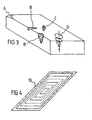
- a camera 1 is provided with a stand 2 of a form which is capable of firmly supporting the camera above a footprint 3.
- the footprint may be formed by an indentation in a pliable substrate or it could have been deposited on a surface as a visible print, or later rendered visible by application of a powder or chemical stain.
- the stand preferably incorporates a rectangular base or frame 4 for accurate positioning about the footprint to ensure constant lateral positioning of the camera.
- the frame also positions the camera at a fixed distance from the image to ensure that there is a predetermined reproduction ratio between the size of the image produced by the camera and the size of the original image. This is important when the system is to be used for producing evidence in legal proceedings since it eliminates any requirement for re-sizing of the digital images.
- the camera could be provided with a sensing system to automatically adjust the size of the received image relative to the size of the imprint, according to the distance between the camera and the surface bearing the imprint.
- a video camera may be used to store images on a video tape from which a still image can be produced using a digitizer or frame grabber.
- a digital camera incorporating a charge-coupled device and which stores the image obtained by the charge-coupled device in internal RAM for later downloading.
- a photographic camera could be used to record the image on photographic film which is later developed and scanned to produce a digital image, or a positive print made from the negative and scanned, this option is undesirable since it introduces the possibility of distortion in the intermediate negative or print.
- the desired end result is a highly accurate bitmapped digital image of the original footprint at a known reproduction ratio.
- bitmapped image is loaded into a computer 30 (Fig. 2) running under specially produced graphics software, and displayed on the screen of a high resolution monitor 31.
- the software displays a pointer which can be moved over the image using a mouse 32, trackball or similar input device.
- bitmapped images are stored and displayed as a rectangular matrix of individual pixels (picture elements) which are individually identified by their x and y co-ordinates.
- the top left corner of the image is conventionally given an x, y co-ordinate of 0, 0.
- Accurate positioning of the footprint image is achieved by providing a range of rectangular boxes for display, which are sized to fit known standard sizes of footwear image.
- Boxes can be selected by the mouse and positioned on the displayed image to enable the smallest box to be chosen which encloses the entire image.
- the area of the image inside the box is then cropped from the image. (Note that cropping does not result in any re-sizing of the footprint image.)
- the footprint image is now positioned at the top left of the displayed box.
- the position of any characterising marks in the sole is visually identified and recorded in computer RAM by positioning the cursor over the feature and clicking the mouse button, the co-ordinates being taken from the top left corner of the cropped image.
- Fig. 3 shows a transparent view of a typical section of the sole of a shoe.
- the set of co-ordinates thereby obtained will provide a unique digital profile of the sole from which the imprint was produced.
- Features can be enhanced by suitable image processing in software. As a simple example, reducing the number of grey levels in an image can often cause features to become more clearly defined.
- the set of co-ordinates is added to a database, which ideally is held at a central location (33 - Fig. 2) remotely accessible using a suitable modem and access code.
- a database which ideally is held at a central location (33 - Fig. 2) remotely accessible using a suitable modem and access code.
- the usefulness of the system is further enhanced by producing bitmapped images from the footwear of known individuals. Suitable apparatus for obtaining such images is described below in relation to Fig. s 7 and 8.
- the co-ordinate information obtained from such images is then added to a second database containing information from known offenders, with which the co-ordinate information taken from prints at the scene of a crime can be compared to facilitate identification of the offender.
- the method is completely non-destructive so that the original imprint is retained in a completely unaltered state.
- the surface bearing the impression can therefore be retained as primary evidence if the substrate bearing the impression is capable of removal for storage. If the impression is left on a fixed surface a gel or adhesive lift, a cast, or a photograph may be taken to retain the primary evidence for later disclosure or production in a court of law.
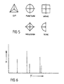
- Fig. 4 shows a screen 10 which can be attached to the frame 4 (Fig. 1) and superimposed on the imprint, to permit accurate and repeatable lateral positioning of the camera relative to the imprint.
- the screen bears a set of concentric etched or engraved rectangles each conforming to a particular size of sole. Other suitable positioning markers could be used.
- the resolution (number of pixels in the footprint image) should also be constant to achieve directly comparable positional data, which is ensured by using a fixed reproduction ratio.
- bitmapped image will be stored on disk or another semi-permanent medium for future reference, but will not usually be added to the database.
- An advantage of the method is that the co-ordinate data requires very little storage space compared with a full bitmapped image. Data processing using the co-ordinate information is therefore very fast so that a large number of records can be searched and compared in a very short period.
- Fig. 5 graphic symbols can be displayed representing different kinds of characterising feature (e.g. cut, puncture, wear, inclusion, tear etc. as illustrated in Fig. 3). Examples of such symbols are shown in Fig. 5. It will be noted that each symbol includes a datum point (represented by a small circle) which is the co-ordinate reference position. By selecting the appropriate symbol with the mouse, positioning the datum point of the symbol on the appropriate area and clicking the mouse, the nature of the feature can be recorded in computer RAM and added to the database if required, to permit more detailed comparisons to be made.
- a datum point represented by a small circle
- Another useful item of information which can be added to the database is the total area of each feature. This is achieved by enlarging the appropriate area of the image sufficiently to render the individual pixels visible, and manually counting the pixels. Another method would be to draw round the area with the mouse and then invoke a sub-routine within the program to calculate the number of pixels enclosed.
- the base line represents the distance of each feature along the y axis of the image, and each recorded feature is represented by a vertical line corresponding in height to the x co-ordinate of the feature.
- Such a graphic representation allows comparison of co-ordinate sets to be easily made by unskilled personnel. The height and position of a line will not change with wear, although some lines will eventually be lost as features disappear with wear. Similarly, other features due to additional damage will produce additional lines in the histogram display. However, provided a series of imprints can be obtained sufficient points of identity will usually be present to allow the history of a piece of footwear to be followed.
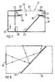
- the apparatus comprises a light-proof box 20 having a rectangular opening 21 provided with a transparent screen 22 to support an item of footwear.
- the size of the opening 21 can be adjusted by means of opaque masks 23 which are slidably positioned along the four sides of the opening to allow the area of the opening to be precisely adjusted to make maximum use of the available area of the image recording medium. This ensures that the image is captured at maximum resolution.
- a scale is marked on the inner margins of the masks to allow the image to be obtained at a known reproduction ratio.
- a light-proof wall 24 is mounted in the light box, having an opening 25 positioned below the opening 21.
- the wall is provided with a further set of laterally adjustable masks 26 which are adjusted to match the size and shape of the opening 25 to the opening 21.
- a set of light sources 27 (preferably strip lights) are mounted between the two sets of masks 23 and 26 at the sides of the openings 25 and 21 to provide oblique illumination of an item of footwear on the screen 22.
- a mirror 27 is mounted at 45° to the opening 25 to direct an image of the footwear towards an aperture 28 formed in the side of the light box 20. Behind this aperture there is mounted a suitable image recording medium 29 such as a camera employing light-sensitive film or a charge-coupled device.
- an item of footwear is placed on the screen 22 with its sole against the screen and covered with opaque material to exclude external light.
- the sole is evenly illuminated by the light sources 27, and as demonstrated in the ray diagram of Fig. 8, the image obtained from the recording medium is laterally reversed.
- the captured bitmapped image can be stored for direct comparison purposes and/or for production in evidence. Co-ordinate data on any identifying features can again be obtained from the image as explained
Abstract
Description
- producing a digital image of an imprint produced by an article;
- displaying said image on a computer screen;
- recording in computer memory identification data relating to features present in said image; storing said identification data in a database together with identification data similarly taken from other images; and
- comparing said identification data utilising an automatic database scanning system to identify articles having similar features;
- said digital images are produced with a predetermined reproduction ratio; and
- said identification data comprises the co-ordinates of any unique identification features in said image caused by use of the article or by manufacturing defects in said article.
Claims (15)
- A method of imprint identification which comprises:characterised in thatproducing a digital image of an imprint produced by an article;displaying said image on a computer screen;recording in computer memory identification data relating to features present in said image;storing said identification data in a database together with identification data similarly taken from other images; andcomparing said identification data utilising an automatic database scanning system to identify articles having similar features;said digital images are produced with a predetermined reproduction ratio; andsaid identification data comprises the co-ordinates of any unique identification features in said image caused by use of the article or by manufacturing defects in said article.
- A method according to Claim 1, in which the digital image is produced by recording a light image derived directly from the imprint.
- A method according to any preceding claim, in which the nature of the identifying feature is recorded in association with each co-ordinate.
- A method according to any preceding claim, in which the area of each feature is recorded in association with each co-ordinate.
- A method according to any preceding claim, in which a stored set of co-ordinates is compared with other stored sets of co-ordinates a plurality of times, with the co-ordinates being incremented or decremented between comparisons.
- A method according to any preceding claim, which comprises graphically displaying a set of stored co-ordinates mapped along two mutually perpendicular axes.
- A method according to any preceding claim, which comprises producing, with a predetermined reproduction ratio, a digital image from an article.
- A method according to Claim 7, in which said digital image produced from said article is displayed on a computer screen and the co-ordinates of any unique identification features in said image are recorded in computer memory.
- A method according to Claim 8, in which the set of co-ordinates thereby produced is stored in a second database for comparison with other stored sets of co-ordinates.
- Apparatus for use in the identification of imprints, which comprises:characterised in thatimage recording means (1) for capturing an image of an imprint;a computer (30) for holding said image in digital form, said computer having a memory, a monitor (31) for displaying said image, and manual input means (32) for inputting into said memory identification data relating to features present in said image and an automatic database scanning system for comparing said identification data to identify articles having similar features; anda database (33) which holds said identification data;said image recording means is provided with means (2) for producing a predetermined reproduction ratio between the imprint and the image; andsaid identification data comprises the co-ordinates of any unique identification features in said image caused by use of the article or by manufacturing defects in said article.
- Apparatus according to Claim 10, in which said means of producing a fixed reproduction ratio comprises a support structure (2) for positioning the recording means relative to an imprint.
- Apparatus according to Claim 10 or 11, comprising a screen (10) carrying positioning markers for superimposing on said imprint.
- Apparatus according to Claim 10, 11 or 12, in which the nature of each identifying feature is recorded in the database in association with each co-ordinate.
- Apparatus according to any of Claims 10 to 13, including a second database containing the co-ordinates of unique identification features present in digital images which are obtained directly from articles. above for inclusion in the database relating to known offenders.
- It will be appreciated that images could also be captured from items of footwear by other means, e.g. by using a laser scanner or the like.
Applications Claiming Priority (3)
| Application Number | Priority Date | Filing Date | Title |
|---|---|---|---|
| GBGB9601955.9A GB9601955D0 (en) | 1996-01-31 | 1996-01-31 | Imprint identification system |
| GB9601955 | 1996-01-31 | ||
| PCT/GB1997/000240 WO1997028513A1 (en) | 1996-01-31 | 1997-01-29 | Imprint identification system |
Publications (3)
| Publication Number | Publication Date |
|---|---|
| EP0877990A1 EP0877990A1 (en) | 1998-11-18 |
| EP0877990B1 EP0877990B1 (en) | 2001-04-18 |
| EP0877990B2 true EP0877990B2 (en) | 2004-01-14 |
Family
ID=10787886
Family Applications (1)
| Application Number | Title | Priority Date | Filing Date |
|---|---|---|---|
| EP97901203A Expired - Lifetime EP0877990B2 (en) | 1996-01-31 | 1997-01-29 | Imprint identification system |
Country Status (7)
| Country | Link |
|---|---|
| US (1) | US6181804B1 (en) |
| EP (1) | EP0877990B2 (en) |
| AT (1) | ATE200714T1 (en) |
| AU (1) | AU1453997A (en) |
| DE (1) | DE69704609T3 (en) |
| GB (1) | GB9601955D0 (en) |
| WO (1) | WO1997028513A1 (en) |
Families Citing this family (4)
| Publication number | Priority date | Publication date | Assignee | Title |
|---|---|---|---|---|
| WO2007095501A2 (en) * | 2006-02-10 | 2007-08-23 | Parallel Synthesis Technologies, Inc. | Authentication and anticounterfeiting methods and devices |
| GB2461880A (en) * | 2008-07-15 | 2010-01-20 | Univ Sheffield | Shoeprint identification system |
| GB2466245A (en) | 2008-12-15 | 2010-06-23 | Univ Sheffield | Crime Scene Mark Identification System |
| CN113562225B (en) * | 2021-07-28 | 2022-09-16 | 中冶赛迪工程技术股份有限公司 | Automatic coil bundling system and method |
Family Cites Families (5)
| Publication number | Priority date | Publication date | Assignee | Title |
|---|---|---|---|---|
| US4607384A (en) * | 1984-05-01 | 1986-08-19 | At&T - Technologies, Inc. | Fingerprint classification arrangement |
| US5025476A (en) * | 1988-10-31 | 1991-06-18 | Nathaniel Gould Diagnostics, Inc. | Redotopography apparatus and method using moire fringe analysis to measure foot shapes |
| US5274714A (en) * | 1990-06-04 | 1993-12-28 | Neuristics, Inc. | Method and apparatus for determining and organizing feature vectors for neural network recognition |
| CA2203297A1 (en) * | 1991-12-13 | 1993-06-14 | American Telephone And Telegraph Company | Intelligent work surfaces |
| US5613014A (en) * | 1994-10-12 | 1997-03-18 | Martin Marietta Corp. | Fingerprint matching system |
-
1996
- 1996-01-31 GB GBGB9601955.9A patent/GB9601955D0/en active Pending
-
1997
- 1997-01-29 AT AT97901203T patent/ATE200714T1/en not_active IP Right Cessation
- 1997-01-29 DE DE69704609T patent/DE69704609T3/en not_active Expired - Lifetime
- 1997-01-29 AU AU14539/97A patent/AU1453997A/en not_active Abandoned
- 1997-01-29 US US09/101,486 patent/US6181804B1/en not_active Expired - Fee Related
- 1997-01-29 EP EP97901203A patent/EP0877990B2/en not_active Expired - Lifetime
- 1997-01-29 WO PCT/GB1997/000240 patent/WO1997028513A1/en active IP Right Grant
Non-Patent Citations (3)
| Title |
|---|
| Bodziak J., "Footwear Impression Evidence", Elsevier Science Publishing Co. 1990, pages 280-282, 288-292, 300, 306, 312, 319, 326-327, 331-332,334, 336-337,341, 345, 347-353, 357, 365 and 374-380 † |
| Liu J H et al, "Fingerprint Comparison. II: On the Development of a Single Fingerprint Filing and Searching System", J. of Forensic Sciences, vol. 27, no. 2, April 1982, pp. 305-317 † |
| Music D K et al, "Evaluation of the Air Bubbles Present in Polyurethane Shoe Outsoles as Applicable in Footwear Impression Comparisons", J. of The Forensic Science Soc., vol. 33, no. 5, pp. 1185-1197, Sept. 1988 † |
Also Published As
| Publication number | Publication date |
|---|---|
| GB9601955D0 (en) | 1996-04-03 |
| DE69704609T2 (en) | 2001-11-29 |
| US6181804B1 (en) | 2001-01-30 |
| ATE200714T1 (en) | 2001-05-15 |
| EP0877990B1 (en) | 2001-04-18 |
| DE69704609T3 (en) | 2005-01-05 |
| EP0877990A1 (en) | 1998-11-18 |
| DE69704609D1 (en) | 2001-05-23 |
| WO1997028513A1 (en) | 1997-08-07 |
| AU1453997A (en) | 1997-08-22 |
Similar Documents
| Publication | Publication Date | Title |
|---|---|---|
| US4958064A (en) | Bar code locator for video scanner/reader system | |
| JP4380838B2 (en) | Video image automatic road sign recognition method, road sign automatic recognition device, and road sign automatic recognition program | |
| US5140647A (en) | Image joining method and system | |
| Brüschweiler et al. | Analysis of patterned injuries and injury-causing instruments with forensic 3D/CAD supported photogrammetry (FPHG): an instruction manual for the documentation process | |
| US6873340B2 (en) | Method and apparatus for an automated reference indicator system for photographic and video images | |
| JP2000517452A (en) | Viewing method | |
| JP2514928B2 (en) | Photogrammetric subject detection method | |
| CN111311556B (en) | Mobile phone defect position identification method and equipment | |
| CN110288612B (en) | Nameplate positioning and correcting method and device | |
| EP0831421A2 (en) | Apparatus and method for retouching a digital representation of a color image | |
| US6606636B1 (en) | Method and apparatus for retrieving dynamic images and method of and apparatus for managing images | |
| EP0877990B2 (en) | Imprint identification system | |
| US6876767B1 (en) | Imprint identification system | |
| USH999H (en) | Transparency distortion measurement process | |
| AU702890B2 (en) | Visual recognition method | |
| KR980004134A (en) | Geographical Names of Satellite Imagery and Methods of Management and Retrieval of Groundwater | |
| JPS60144884A (en) | Detecting method of printed letter | |
| JP3416341B2 (en) | Image Position Recognition Method for Region of Interest in Image | |
| Goss et al. | Three-dimensional visualization environment for multisensor data analysis, interpretation, and model-based object recognition | |
| JPH09128537A (en) | Method and device for collating seal impression | |
| JP2002216114A (en) | Three-dimensional model generating method | |
| Boulianne et al. | Design and implementation of new digital video plotter (DVP) features | |
| EP0282652A1 (en) | A method of documenting two- or three-dimensional objects | |
| KR20040002616A (en) | A Method for Extracting Digital data from Record Line On Automatic Recording Papers | |
| JPH1196373A (en) | Image pickup device |
Legal Events
| Date | Code | Title | Description |
|---|---|---|---|
| PUAI | Public reference made under article 153(3) epc to a published international application that has entered the european phase |
Free format text: ORIGINAL CODE: 0009012 |
|
| 17P | Request for examination filed |
Effective date: 19980825 |
|
| AK | Designated contracting states |
Kind code of ref document: A1 Designated state(s): AT BE CH DE DK ES FI FR GB GR IE IT LI LU MC NL PT SE |
|
| 17Q | First examination report despatched |
Effective date: 19990930 |
|
| GRAG | Despatch of communication of intention to grant |
Free format text: ORIGINAL CODE: EPIDOS AGRA |
|
| GRAG | Despatch of communication of intention to grant |
Free format text: ORIGINAL CODE: EPIDOS AGRA |
|
| GRAH | Despatch of communication of intention to grant a patent |
Free format text: ORIGINAL CODE: EPIDOS IGRA |
|
| GRAH | Despatch of communication of intention to grant a patent |
Free format text: ORIGINAL CODE: EPIDOS IGRA |
|
| GRAA | (expected) grant |
Free format text: ORIGINAL CODE: 0009210 |
|
| AK | Designated contracting states |
Kind code of ref document: B1 Designated state(s): AT BE CH DE DK ES FI FR GB GR IE IT LI LU MC NL PT SE |
|
| PG25 | Lapsed in a contracting state [announced via postgrant information from national office to epo] |
Ref country code: LI Free format text: LAPSE BECAUSE OF FAILURE TO SUBMIT A TRANSLATION OF THE DESCRIPTION OR TO PAY THE FEE WITHIN THE PRESCRIBED TIME-LIMIT Effective date: 20010418 Ref country code: IT Free format text: LAPSE BECAUSE OF FAILURE TO SUBMIT A TRANSLATION OF THE DESCRIPTION OR TO PAY THE FEE WITHIN THE PRE;WARNING: LAPSES OF ITALIAN PATENTS WITH EFFECTIVE DATE BEFORE 2007 MAY HAVE OCCURRED AT ANY TIME BEFORE 2007. THE CORRECT EFFECTIVE DATE MAY BE DIFFERENT FROM THE ONE RECORDED.SCRIBED TIME-LIMIT Effective date: 20010418 Ref country code: FR Free format text: LAPSE BECAUSE OF FAILURE TO SUBMIT A TRANSLATION OF THE DESCRIPTION OR TO PAY THE FEE WITHIN THE PRESCRIBED TIME-LIMIT Effective date: 20010418 Ref country code: FI Free format text: LAPSE BECAUSE OF FAILURE TO SUBMIT A TRANSLATION OF THE DESCRIPTION OR TO PAY THE FEE WITHIN THE PRESCRIBED TIME-LIMIT Effective date: 20010418 Ref country code: CH Free format text: LAPSE BECAUSE OF FAILURE TO SUBMIT A TRANSLATION OF THE DESCRIPTION OR TO PAY THE FEE WITHIN THE PRESCRIBED TIME-LIMIT Effective date: 20010418 Ref country code: AT Free format text: LAPSE BECAUSE OF FAILURE TO SUBMIT A TRANSLATION OF THE DESCRIPTION OR TO PAY THE FEE WITHIN THE PRESCRIBED TIME-LIMIT Effective date: 20010418 |
|
| REF | Corresponds to: |
Ref document number: 200714 Country of ref document: AT Date of ref document: 20010515 Kind code of ref document: T |
|
| REG | Reference to a national code |
Ref country code: CH Ref legal event code: EP |
|
| REF | Corresponds to: |
Ref document number: 69704609 Country of ref document: DE Date of ref document: 20010523 |
|
| REG | Reference to a national code |
Ref country code: IE Ref legal event code: FG4D |
|
| PG25 | Lapsed in a contracting state [announced via postgrant information from national office to epo] |
Ref country code: SE Free format text: LAPSE BECAUSE OF FAILURE TO SUBMIT A TRANSLATION OF THE DESCRIPTION OR TO PAY THE FEE WITHIN THE PRESCRIBED TIME-LIMIT Effective date: 20010718 Ref country code: PT Free format text: LAPSE BECAUSE OF FAILURE TO SUBMIT A TRANSLATION OF THE DESCRIPTION OR TO PAY THE FEE WITHIN THE PRESCRIBED TIME-LIMIT Effective date: 20010718 Ref country code: DK Free format text: LAPSE BECAUSE OF FAILURE TO SUBMIT A TRANSLATION OF THE DESCRIPTION OR TO PAY THE FEE WITHIN THE PRESCRIBED TIME-LIMIT Effective date: 20010718 |
|
| EN | Fr: translation not filed | ||
| PG25 | Lapsed in a contracting state [announced via postgrant information from national office to epo] |
Ref country code: ES Free format text: LAPSE BECAUSE OF FAILURE TO SUBMIT A TRANSLATION OF THE DESCRIPTION OR TO PAY THE FEE WITHIN THE PRESCRIBED TIME-LIMIT Effective date: 20011030 |
|
| REG | Reference to a national code |
Ref country code: CH Ref legal event code: PL |
|
| REG | Reference to a national code |
Ref country code: GB Ref legal event code: IF02 |
|
| PLBQ | Unpublished change to opponent data |
Free format text: ORIGINAL CODE: EPIDOS OPPO |
|
| PLBI | Opposition filed |
Free format text: ORIGINAL CODE: 0009260 |
|
| PG25 | Lapsed in a contracting state [announced via postgrant information from national office to epo] |
Ref country code: LU Free format text: LAPSE BECAUSE OF NON-PAYMENT OF DUE FEES Effective date: 20020129 |
|
| PG25 | Lapsed in a contracting state [announced via postgrant information from national office to epo] |
Ref country code: GR Free format text: LAPSE BECAUSE OF FAILURE TO SUBMIT A TRANSLATION OF THE DESCRIPTION OR TO PAY THE FEE WITHIN THE PRESCRIBED TIME-LIMIT Effective date: 20020131 |
|
| PLBF | Reply of patent proprietor to notice(s) of opposition |
Free format text: ORIGINAL CODE: EPIDOS OBSO |
|
| 26 | Opposition filed |
Opponent name: THE SECRETARY OF STATE FOR THE HOME DEPARTMENT C/O Effective date: 20020118 |
|
| NLR1 | Nl: opposition has been filed with the epo |
Opponent name: THE SECRETARY OF STATE FOR THE HOME DEPARTMENT C/O |
|
| PLBF | Reply of patent proprietor to notice(s) of opposition |
Free format text: ORIGINAL CODE: EPIDOS OBSO |
|
| PG25 | Lapsed in a contracting state [announced via postgrant information from national office to epo] |
Ref country code: MC Free format text: LAPSE BECAUSE OF NON-PAYMENT OF DUE FEES Effective date: 20020801 |
|
| PLAW | Interlocutory decision in opposition |
Free format text: ORIGINAL CODE: EPIDOS IDOP |
|
| PUAH | Patent maintained in amended form |
Free format text: ORIGINAL CODE: 0009272 |
|
| STAA | Information on the status of an ep patent application or granted ep patent |
Free format text: STATUS: PATENT MAINTAINED AS AMENDED |
|
| 27A | Patent maintained in amended form |
Effective date: 20040114 |
|
| AK | Designated contracting states |
Kind code of ref document: B2 Designated state(s): AT BE CH DE DK ES FI FR GB GR IE IT LI LU MC NL PT SE |
|
| NLR2 | Nl: decision of opposition |
Effective date: 20040114 |
|
| NLR3 | Nl: receipt of modified translations in the netherlands language after an opposition procedure | ||
| REG | Reference to a national code |
Ref country code: DE Ref legal event code: 8570 |
|
| EN | Fr: translation not filed | ||
| REG | Reference to a national code |
Ref country code: GB Ref legal event code: S71 |
|
| REG | Reference to a national code |
Ref country code: GB Ref legal event code: S71 |
|
| PGFP | Annual fee paid to national office [announced via postgrant information from national office to epo] |
Ref country code: NL Payment date: 20101102 Year of fee payment: 15 |
|
| PGFP | Annual fee paid to national office [announced via postgrant information from national office to epo] |
Ref country code: BE Payment date: 20101029 Year of fee payment: 15 |
|
| PGFP | Annual fee paid to national office [announced via postgrant information from national office to epo] |
Ref country code: DE Payment date: 20101029 Year of fee payment: 15 |
|
| PGFP | Annual fee paid to national office [announced via postgrant information from national office to epo] |
Ref country code: IE Payment date: 20120125 Year of fee payment: 16 |
|
| BERE | Be: lapsed |
Owner name: *CROSSLING DUDLEY BRYAN Effective date: 20120131 |
|
| REG | Reference to a national code |
Ref country code: NL Ref legal event code: V1 Effective date: 20120801 |
|
| PG25 | Lapsed in a contracting state [announced via postgrant information from national office to epo] |
Ref country code: DE Free format text: LAPSE BECAUSE OF FAILURE TO SUBMIT A TRANSLATION OF THE DESCRIPTION OR TO PAY THE FEE WITHIN THE PRESCRIBED TIME-LIMIT Effective date: 20120801 |
|
| REG | Reference to a national code |
Ref country code: DE Ref legal event code: R119 Ref document number: 69704609 Country of ref document: DE Effective date: 20120801 |
|
| PG25 | Lapsed in a contracting state [announced via postgrant information from national office to epo] |
Ref country code: BE Free format text: LAPSE BECAUSE OF NON-PAYMENT OF DUE FEES Effective date: 20120131 |
|
| PG25 | Lapsed in a contracting state [announced via postgrant information from national office to epo] |
Ref country code: NL Free format text: LAPSE BECAUSE OF NON-PAYMENT OF DUE FEES Effective date: 20120801 |
|
| REG | Reference to a national code |
Ref country code: IE Ref legal event code: MM4A |
|
| PG25 | Lapsed in a contracting state [announced via postgrant information from national office to epo] |
Ref country code: IE Free format text: LAPSE BECAUSE OF NON-PAYMENT OF DUE FEES Effective date: 20130129 |
|
| PGFP | Annual fee paid to national office [announced via postgrant information from national office to epo] |
Ref country code: GB Payment date: 20131101 Year of fee payment: 18 |
|
| GBPC | Gb: european patent ceased through non-payment of renewal fee |
Effective date: 20150129 |
|
| PG25 | Lapsed in a contracting state [announced via postgrant information from national office to epo] |
Ref country code: GB Free format text: LAPSE BECAUSE OF NON-PAYMENT OF DUE FEES Effective date: 20150129 |