EP0877640B1 - Armangetriebenes laufband - Google Patents
Armangetriebenes laufband Download PDFInfo
- Publication number
- EP0877640B1 EP0877640B1 EP97902910A EP97902910A EP0877640B1 EP 0877640 B1 EP0877640 B1 EP 0877640B1 EP 97902910 A EP97902910 A EP 97902910A EP 97902910 A EP97902910 A EP 97902910A EP 0877640 B1 EP0877640 B1 EP 0877640B1
- Authority
- EP
- European Patent Office
- Prior art keywords
- belt
- treadmill
- arm
- members
- user
- Prior art date
- Legal status (The legal status is an assumption and is not a legal conclusion. Google has not performed a legal analysis and makes no representation as to the accuracy of the status listed.)
- Expired - Lifetime
Links
- 230000033001 locomotion Effects 0.000 claims abstract description 63
- 230000005540 biological transmission Effects 0.000 claims abstract description 18
- 238000006073 displacement reaction Methods 0.000 claims abstract description 10
- 238000000034 method Methods 0.000 claims description 9
- 230000008878 coupling Effects 0.000 claims description 5
- 238000010168 coupling process Methods 0.000 claims description 5
- 238000005859 coupling reaction Methods 0.000 claims description 5
- 230000007246 mechanism Effects 0.000 abstract description 8
- 230000008901 benefit Effects 0.000 description 3
- 238000004146 energy storage Methods 0.000 description 3
- 238000010276 construction Methods 0.000 description 2
- 238000012986 modification Methods 0.000 description 2
- 230000004048 modification Effects 0.000 description 2
- 238000004804 winding Methods 0.000 description 2
- 230000009286 beneficial effect Effects 0.000 description 1
- 210000000748 cardiovascular system Anatomy 0.000 description 1
- 230000008859 change Effects 0.000 description 1
- 230000003247 decreasing effect Effects 0.000 description 1
- 230000000694 effects Effects 0.000 description 1
- 238000009432 framing Methods 0.000 description 1
- 230000005484 gravity Effects 0.000 description 1
- 238000009499 grossing Methods 0.000 description 1
- 230000009347 mechanical transmission Effects 0.000 description 1
- 210000003205 muscle Anatomy 0.000 description 1
- 230000001681 protective effect Effects 0.000 description 1
- 210000002027 skeletal muscle Anatomy 0.000 description 1
- 238000009987 spinning Methods 0.000 description 1
- 230000001131 transforming effect Effects 0.000 description 1
- 230000007704 transition Effects 0.000 description 1
Images



Classifications
-
- A—HUMAN NECESSITIES
- A63—SPORTS; GAMES; AMUSEMENTS
- A63B—APPARATUS FOR PHYSICAL TRAINING, GYMNASTICS, SWIMMING, CLIMBING, OR FENCING; BALL GAMES; TRAINING EQUIPMENT
- A63B22/00—Exercising apparatus specially adapted for conditioning the cardio-vascular system, for training agility or co-ordination of movements
- A63B22/02—Exercising apparatus specially adapted for conditioning the cardio-vascular system, for training agility or co-ordination of movements with movable endless bands, e.g. treadmills
-
- A—HUMAN NECESSITIES
- A63—SPORTS; GAMES; AMUSEMENTS
- A63B—APPARATUS FOR PHYSICAL TRAINING, GYMNASTICS, SWIMMING, CLIMBING, OR FENCING; BALL GAMES; TRAINING EQUIPMENT
- A63B21/00—Exercising apparatus for developing or strengthening the muscles or joints of the body by working against a counterforce, with or without measuring devices
- A63B21/15—Arrangements for force transmissions
- A63B21/151—Using flexible elements for reciprocating movements, e.g. ropes or chains
- A63B21/154—Using flexible elements for reciprocating movements, e.g. ropes or chains using special pulley-assemblies
-
- A—HUMAN NECESSITIES
- A63—SPORTS; GAMES; AMUSEMENTS
- A63B—APPARATUS FOR PHYSICAL TRAINING, GYMNASTICS, SWIMMING, CLIMBING, OR FENCING; BALL GAMES; TRAINING EQUIPMENT
- A63B21/00—Exercising apparatus for developing or strengthening the muscles or joints of the body by working against a counterforce, with or without measuring devices
- A63B21/40—Interfaces with the user related to strength training; Details thereof
- A63B21/4027—Specific exercise interfaces
- A63B21/4033—Handles, pedals, bars or platforms
- A63B21/4035—Handles, pedals, bars or platforms for operation by hand
-
- A—HUMAN NECESSITIES
- A63—SPORTS; GAMES; AMUSEMENTS
- A63B—APPARATUS FOR PHYSICAL TRAINING, GYMNASTICS, SWIMMING, CLIMBING, OR FENCING; BALL GAMES; TRAINING EQUIPMENT
- A63B21/00—Exercising apparatus for developing or strengthening the muscles or joints of the body by working against a counterforce, with or without measuring devices
- A63B21/40—Interfaces with the user related to strength training; Details thereof
- A63B21/4041—Interfaces with the user related to strength training; Details thereof characterised by the movements of the interface
- A63B21/4047—Pivoting movement
-
- A—HUMAN NECESSITIES
- A63—SPORTS; GAMES; AMUSEMENTS
- A63B—APPARATUS FOR PHYSICAL TRAINING, GYMNASTICS, SWIMMING, CLIMBING, OR FENCING; BALL GAMES; TRAINING EQUIPMENT
- A63B22/00—Exercising apparatus specially adapted for conditioning the cardio-vascular system, for training agility or co-ordination of movements
- A63B22/0002—Exercising apparatus specially adapted for conditioning the cardio-vascular system, for training agility or co-ordination of movements involving an exercising of arms
- A63B22/001—Exercising apparatus specially adapted for conditioning the cardio-vascular system, for training agility or co-ordination of movements involving an exercising of arms by simultaneously exercising arms and legs, e.g. diagonally in anti-phase
- A63B22/0012—Exercising apparatus specially adapted for conditioning the cardio-vascular system, for training agility or co-ordination of movements involving an exercising of arms by simultaneously exercising arms and legs, e.g. diagonally in anti-phase the exercises for arms and legs being functionally independent
-
- A—HUMAN NECESSITIES
- A63—SPORTS; GAMES; AMUSEMENTS
- A63B—APPARATUS FOR PHYSICAL TRAINING, GYMNASTICS, SWIMMING, CLIMBING, OR FENCING; BALL GAMES; TRAINING EQUIPMENT
- A63B21/00—Exercising apparatus for developing or strengthening the muscles or joints of the body by working against a counterforce, with or without measuring devices
- A63B21/012—Exercising apparatus for developing or strengthening the muscles or joints of the body by working against a counterforce, with or without measuring devices using frictional force-resisters
- A63B21/015—Exercising apparatus for developing or strengthening the muscles or joints of the body by working against a counterforce, with or without measuring devices using frictional force-resisters including rotating or oscillating elements rubbing against fixed elements
-
- A—HUMAN NECESSITIES
- A63—SPORTS; GAMES; AMUSEMENTS
- A63B—APPARATUS FOR PHYSICAL TRAINING, GYMNASTICS, SWIMMING, CLIMBING, OR FENCING; BALL GAMES; TRAINING EQUIPMENT
- A63B2225/00—Miscellaneous features of sport apparatus, devices or equipment
- A63B2225/09—Adjustable dimensions
- A63B2225/093—Height
-
- A—HUMAN NECESSITIES
- A63—SPORTS; GAMES; AMUSEMENTS
- A63B—APPARATUS FOR PHYSICAL TRAINING, GYMNASTICS, SWIMMING, CLIMBING, OR FENCING; BALL GAMES; TRAINING EQUIPMENT
- A63B2225/00—Miscellaneous features of sport apparatus, devices or equipment
- A63B2225/30—Maintenance
Definitions
- the invention relates generally to exercise equipment, and in particular to a treadmill for exercising the upper and lower body of a user comprising: a substantially stationary support frame, an endless belt longitudinally encircling the support frame, a pair of substantially upright arm members astride the belt extending upwardly to a corresponding pair of handles for gripping by the hands of the user, the upright members being displaceable by forward and rearward arm movements of the user to move in a reciprocating motion.
- Conventional treadmills employ a motor to rearwardly drive an endless belt.
- a user of a conventional treadmill is able to vary the speed and incline of the treadmill to obtain a desired level of workout.
- More sophisticated treadmills such as described in U.S. Patent No. 5,462,504 and assigned to the assignee of the present application, automatically adjust the speed and incline of the treadmill to controll the heart rate of the user.
- treadmills function to exercise the user's cardiovascular system and the skeletal muscles of the lower body, but do not exercise the upper body to any significant extent. Accordingly, a number of treadmills have upper body exercise devices associated therewith, such as arm members which are moveable against the resistance of a spring.
- motors need maintance, can fail, need to be plugged into a power source and add to the weight of the treadmill, while the expense of the motor is a major factor in treadmill purchases.
- TW235488 (Application No. 83206915) discloses an arm powered treadmill in which lever handle means are pivotally connected to the two sides of the base and movable forward and rearward, two connecting members each having a first end pivotally connected to the lever handle means to form a front and rear pulling connection, the connecting members being sleeved unto the transmission wheels to form coupled transmission, the second end of the connecting member being joined to an elastic rope, said elastic rope being pivotally connected to a side of the base.
- Another object is to provide a treadmill as characterized above which is lightweight in design and relatively uncomplicated.
- the present invention provides a treadmill for exercising the upper body and lower body of a user, wherein displacement of an upper-body exercise means drives an endless belt to rotate in one direction around the support frame.
- the treadmill includes a substantially stationary support frame, an endless belt longitudinally encircling the support frame, a pair of substantially upright arm members astride the belt extending upwardly to a corresponding pair of handles for gripping by the hands of the user, the upright members being displaceable by forward and rearward arm movements of the user to move in a reciprocating motion, a drive roller coupled to the belt, a transmission system linking the drive roller to the arm members such that displacement of each of the arm members drives the belt to rotate in one direction around the support frame, a linkage coupling the reciprocating motion of one arm member to the reciprocating motion of the other arm member such that the displacement of each of the arm members in both forward and rearward directions drives rotation of the belt.
- the transmission system includes a pulley system.
- the pulley system includes at least one drive pulley coupled to the drive roller for rotation thereof and at least one displaceable pulley coupled to one of the upright arm members for displacement thereby, and further comprises a cable connected between the pulleys such that displacement of the displaceable pulley is translated to the cable into rotation of the drive roller pulley.
- the inventive treadmill has a ratio of arm movement distance to belt movement distance which is approximately between 0.6 and 2.
- inventive treadmill further comprises means for controllably arresting the angle of inclination of the treadmill.
- the treadmill comprises a breaking device for opposing rotation of the belt.
- a still further improved embodiment comprises a breaking device for opposing rotation of the belt where in the breaking device is motorized and controlled by a switch proximate one of the handles.
- the inventive treadmill comprises means for adjusting the length of at least one of the upright members.
- inventive treadmill includes means for adjusting the length of at least one of the upright members such means comprising telescoping sub-members.
- the inventive treadmill includes a flywheel for storing the kinetic energy of the reciprocating motion of the upright members and for steadily releasing the stored energy to smooth the rotational movement of the belt.
- the treadmill includes means for rotating the flywheel at three times the speed of the drive roller.
- the upper ends of the upright members are angled relative to the lower ends.
- the present invention further resides in a method of assisting the rotation of a treadmill belt, comprising the steps of:
- a preferred method further comprises the step of providing a belt roller connected to the belt for rearward rotation thereof, and the step of transforming the kinetic energy of arm movements comprises a step of rotating a pulley coupled to rotate the drive roller rearwardly.
- the same comprises the steps of storing the energy of arm movement and releasing the stored energy at a more constant rate than stored to smooth the rearward movement of the belt.
- the method comprises the step of applying a breaking force to impede movement of the belt.
- FIGS. 1 and 2 there is shown a treadmill generally designated 10 including an endless belt 12 riding upon a low-friction support surface 13 supported by a base 14.
- the base 14 is slightly elevated at its forward end with respect to its rearward end such that it is inclined at an angle of six degrees relative to a level surface.
- the treadmill may be arranged such that the incline may be varied by any suitable means, such as by providing manually or automatically adjustable feet or framing members, including pneumatic or hydraulic actuators, or motor-driven elevation means.
- one suitable motor driven elevation means that operates by raising the base with respect to an underlying frame member is described in U.S. Patent No. 5,462,504, incorporated herein by reference in its entirety.
- the treadmill 10 includes generally upright left and right arm members 16a and 16b, respectively, from the perspective of the user, (i.e. walking up the inclined belt).
- the arm members 16a and 16b are preferably of a length wherein a user can grasp them in a reasonably comfortable position when striding, and such that the user's arms and upper body are exercised by movement thereof without overburdening any particular muscle group.
- the arm members may be adjustable in length, as described in more detail below.
- the base 14 supports the belt 12 and support surface 13, and further serves as a protective housing to prevent users from contacting the moving parts.
- the base 14 also includes triangular shaped coverings 18a and 18b which protect the user from the movement of the arms. below pivot points 19a and 19b where the arms 16a, 16b are pivotally coupled to the base 14.
- the movement of the arm members 16a and 16b power a transmission system generally designated 20 that rotates the belt 12 rearwardly.
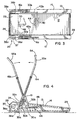
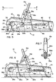
- the reciprocating lower ends of the arm members 16a and 16b wind and unwind a cable 24 on a pulley system 26 that rotates a forward drive roller 28 e.g., in a clockwise direction from the perspective of FIG. 6.
- a forward drive roller 28 rotates, the belt 12, which is coupled thereto so as to not slip under ordinary loads, rotates rearwardly.
- the belt 12 may be arranged so as to not slip on the drive roller 28 by providing proper tensioning, coefficients of friction and/or having treads in the underside of the belt 12 engage with counterpart treads (not shown) on the drive roller 28.
- a rear roller 29 is provided at the rear of the treadmill to redirect the belt 12 forwardly. As can be appreciated, the actual functions of the rollers can be reversed, e.g., if desired, the rear roller 29 can be mechanically arranged to function as the driving roller.
- the pulley system 22 includes left and right reciprocating pulley wheels 30a and 30b coupled to lower ends of the arm members 16a and 16b, respectively.
- each arm member 16a, 16b includes a fork-shaped mounting 32a, 32b for supporting the reciprocating pulley wheels 30a, 30b between the forks thereof on axles 34a, 34b.
- the cable 24 is fixed at each end thereof by a bolt or the like 35a, 35b to each side of the base 14.
- the cable is redirected around free-wheeling pulley wheel 30a and in turn around a pulley wheel 36a which is coupled to a drive roller axle 37 to rotate the drive roller 28.
- the cable 24 is redirected across the front of the treadmill 10 by rollers 38a and 38b.
- the rollers 38a and 38b are disposed so that the cable traverses the front of treadmill 10 slightly in front of the axis of the drive roller 28, and are thus preferably oriented at an angle to correspond with the angle of the cable at that point.
- the right side of the cable is wound around a pulley wheel 36b similarly coupled to the opposite side of the axle 37 to rotate the drive roller 28.
- the right side of the belt is arranged to be symmetrical to the left side, and is thus similarly engaged with right pulley wheel 30b before being fixed by bolt 35b to the right side of the base 14.
- the pulley wheels 36a and 36b connected thereto include one-way bearings, as described in more detail below.
- Such bearings are commercially available from Torrington Corporation, Torrington, Connecticut, Part No. RCB162117.
- the arms are joined at their lower ends through a linkage 40.
- the linkage 40 is pivotally connected to rearwardly extending rods 42a, 42b which in turn are coupled to their respective arm portions 16a, 16b at the axles 34a, 34b thereof.
- the linkage 40 is pivoted at its center to by a pin or the like in a support block 44 fixed with respect to the base 14.
- the support block 44 may be coupled to the underside of the support surface 13, or may be supported by a similar lower surface or by a transverse support bar (not shown). If the linkage 40 is longer than the width of the inner walls of the base 14, slots 46 or the like may be provided to facilitate movement of the linkage ends.
- the cable 24 rotates the pulley wheels 30a, 30b and 36a, 36b as it moves with the changing distances between those wheels.
- the rearward movement of the lower end of arm member 16a rotates wheel 36a in the desired clockwise direction, and thus the one-way bearings are arranged to impart this motion to the drive roller 28.
- the forward movement of the arm i.e., from FIG. 6 to FIG. 5 rotates wheel 36a counterclockwise, and thus the one-way bearings allow wheel 36a to free-wheel at this time.
- the right side of the pulley system 26 works in the same manner as the left side, i.e., increasing the distance between the right side pulleys 30b and 36b powers the drive roller 28, while the reverse movement has no effect.
- the arm members 16a, 16b are coupled together by the cable 28.
- the ratio of the diameter of the drive roller 28 to the diameters of the various pulleys 30a, 30b and 36a, 36b and the mechanical advantage obtained by the pulley winding ratio has been selected such that a normal length stride corresponds to a normal amount of arm movement for an average user. More particularly, a 23.8 inch maximum arm stroke produces 25.4 inches of belt travel (1.07 to 1.00 belt-to-arm travel) as a result of a 2.33 to 1.00 roller to pulley diameter ratio, and a 2.00 to 1.00 pulley winding ratio. Of course, benefits would be obtained with other ratios of arm movement to belt travel, e.g., from five to thirty inches of arm movement producing anywhere from three to sixty inches of belt travel.
- the treadmill is preferably inclined at six degrees to horizontal, thereby utilizing the weight of the user to assist the force that is supplied by the user's arm movements.
- the incline may be varied. In either situation, however, the speed of the arm movement, which corresponds to the speed of the stride, helps determine the belt speed absent belt slippage.
- the ratio of arm movement to belt travel is not solely a function of the gear ratio, but is also determined by the weight of the user in conjunction with the incline. For example, with sufficient incline the belt will move freely without any arm movement as a result of the weight of the user. With arm assistance, the belt typically moves further than the gearing alone would dictate because of the weight in conjunction with the incline and because one-way bearings are employed.
- the conservation of angular momentum due to the mass and other dimensions of the roller, acts as an energy storage means to make the belt rotation smooth during the transitions from forward to rearward arm movements.
- an additional energy storage means such as a separate flywheel or the like may be added to further smooth the belt rotation.
- a flywheel 60 may be provided to augment the initial mass of the drive roller 28 and store rotational energy, thereby further smoothing belt rotation.
- the flywheel 60 comprises a metallic disc or the like rotating on the same axle 37 as the drive roller 28. As shown in FIG. 11, the flywheel 60 returns stored energy to the drive roller 28 via a drive belt system 62. Instead of directly driving the drive roller 28, the transmission system 20 is arranged to rotate the flywheel 60 in one direction using one way bearings as previously described. As the flywheel 60 is rotated, a belt system 62 comprising a first drive belt 64 coupled to an axle 65 of the flywheel 60 rotates a transmission pulley wheel 66. In turn, the transmission pulley wheel 66 rotates a second drive belt 68 coupled to rotate the drive roller 28. Because of the one way bearings, when the arm movement is halted and/or reversed, the flywheel 60 continues to rotate, continually releasing rotational energy to the drive roller 28.
- the flywheel 60 rotates at three times the rotational speed of the drive roller 28.
- the flywheel may be connected to the rear roller, or can be independent of either roller such as by separately coupling to the belt.
- a braking system to selectively and/or gradually stop the flywheel upon user demand may also be provided.
- a braking device 48 may be added to regulate the amount of arm force needed to drive the belt, by providing an adjustable frictional force against the drive roller 28.
- the braking device 48 may be mounted to the base 14 in a manner similar to the support block 44, or may be disposed near one side of the base 14 and mounted directly to the base 14 at that side.
- a brake pad 50 is moved forwardly or rearwardly with respect to the drive roller 28.
- this is accomplished by operating a small motor 52 from a switch 54 disposed on one of the handles 55a, 55b of the arms 16a or 16b.
- a DC motor manufactured by Dayton Corporation, Chicago, Illinois, Model No. 2L003, has been connected to a twelve-volt battery 56 for this purpose.
- any suitable motor 52 with appropriate power supply 56, or any manual braking system, will suffice.
- the treadmill of the present invention may still be considered a substantially motorless device, because the weight, reliability and/or cordless operation of such a small, battery-powered motor is significantly different with respect to drive motors in conventional treadmills.
- the braking device 48 ensures that some force must be applied by the user's arms to power the belt 12 regardless of the incline of the treadmill 10 or the weight of the user. As can be appreciated, the braking device 48 is particularly beneficial when attempting to regulate the speed via arm motion with treadmills capable of variable inclines. Moreover, the braking device 48 provides a user with the ability to exercise the upper body a certain amount with respect to the lower body, as the brake setting influences whether a small or large amount of arm force is necessary to move the belt 12. Indeed, it is feasible to regulate the brake setting and/or the incline to control the heart rate of the user.
- each handle 55a or 55b may be angled with respect to its corresponding arm member 16a or 16b, respectively.
- the arm members 16a, 16b may be variable in length.
- each arm member such as 16a may comprise telescoping sub-members 70 and 72, wherein the outer diameter of one of the sub-members slidably fits within the inner diameter of the other.
- a tightening collar 74 or the like may be provided to lock the sub-members together at the desired relative lengths.
- Other ways of providing variable length arm members such as by having sub-members with complimentary screw threads, may be alternatively provided.
- the preferred transmission mechanism 20 which has been successfully operated in a prototype apparatus, employs a pulley-based, mechanical transmission mechanism 20, other non-motorized transmission mechanisms are contemplated by the present invention.
- suitable transmission mechanisms for converting arm movement to belt rotation may include a meshed gear arrangement, planetary gearing systems, and hydraulic, pneumatic or electromagnetic based systems.
- a motorless treadmill that exercises the upper and lower body of a user.
- the treadmill belt moves such that the stride of a user feels relatively natural even as the user varies the speed.
- the amount of upper body exercise can be varied with respect to the amount of lower body exercise.
- the treadmill is lightweight in design and relatively uncomplicated.
Landscapes
- Health & Medical Sciences (AREA)
- General Health & Medical Sciences (AREA)
- Physical Education & Sports Medicine (AREA)
- Life Sciences & Earth Sciences (AREA)
- Biophysics (AREA)
- Orthopedic Medicine & Surgery (AREA)
- Cardiology (AREA)
- Vascular Medicine (AREA)
- Rehabilitation Tools (AREA)
Claims (16)
- Laufband (10) zum Trainieren des Oberkörpers und Unterkörpers eines Benutzers, umfassend:einen im Wesentlichen stationären Stützrahmen (14), ein Endlosband (12), welches der Länge nach den Stützrahmen (14) umschließt und ein Paar von im Wesentlichen aufrechten Armteilen (16a, 16b) quer zum Band (12), die sich aufwärts bis zu einem entsprechenden Paar mit den Händen des Benutzers zu fassenden Griffstücken (55a, 55b) erstrecken, wobei die aufrechten Teile (16a, 16b) durch Vorwärts- und Rückwärtsbewegungen der Arme des Benutzers verlagerbar sind, um eine Hin- und Herbewegung auszuführen, eine Antriebswalze (28), die mit dem Band (12) gekoppelt ist, ein Übertragungssystem (20), welches die Antriebswalze (28) mit den Armteilen (16a, 16b) derart koppelt, dass eine Verlagerung eines jeden der Armteile (16a, 16b) das Band (12) antreibt, sich in einer Richtung um den Stützrahmen (14) zu drehen, dadurch gekennzeichnet, dass es weiter eine Kopplung (40) umfasst, welche die Hin- und Herbewegung eines Armteils (16a, 16b) mit der Hin- und Herbewegung des anderen Armteils (16a, 16b) derart koppelt, dass die Verlagerung eines jeden der Armteile (16a, 16b) sowohl in Vorwärts- als auch in Rückwärtsrichtung die Drehbewegung des Bandes (12) antreibt.
- Laufband (10) gemäß Anspruch 1, wobei das Übertragungssystem (20) ein Riemenscheibensystem (22) umfasst.
- Laufband (10) gemäß Anspruch 2, wobei das Riemenscheibensystem (22) mindestens eine Antriebsscheibe, die mit der Antriebswalze (28) zur Drehung derselben gekoppelt ist, und mindestens eine verlagerbare Riemenscheibe, die mit einem der aufrechten Armteile (16a; 16b) zur Verlagerung mit demselben gekoppelt ist, und weiter ein Seil (24) umfasst, das derart zwischen den Riemenscheiben verbunden ist, dass die Verlagerung der verlagerbaren Riemenscheibe über das Seil (24) in eine Drehbewegung der Riemenscheibe der Antriebswalze umgesetzt wird.
- Laufband (10) gemäß Anspruch 1, wobei das Verhältnis der Wegstrecke der Armbewegung zur Wegstrecke der Bandbewegung annäherungsweise zwischen 0,6 und 2 ist.
- Laufband (10) gemäß Anspruch 1, weiter umfassend Mittel, um den Neigungswinkel des Laufbandes (10) entsprechend von Vorgaben einzustellen.
- Laufband (10) gemäß Anspruch 1, weiter umfassend eine Bremsvorrichtung (48), um der Drehung des Bandes (12) entgegenzuwirken.
- Laufband (10) gemäß Anspruch 1, weiter umfassend eine Bremsvorrichtung (48), um der Drehung des Bandes (12) entgegenzuwirken, wobei die Bremsvorrichtung (48) motorisiert ist und über einen Schalter (54) nahe bei einem der Griffstücke (55a; 55b) kontrolliert wird.
- Laufband (10) gemäß Anspruch 3, weiter umfassend Mittel zum Einstellen der Länge von mindestens einem der aufrechten Teile (16a, 16b).
- Laufband (10) gemäß Anspruch 8, wobei die Mittel zum Einstellen der Länge von mindestens einem der aufrechten Teile ineinanderschiebbare Abschnitte der Teile (70, 72) umfasst.
- Laufband (10) gemäß Anspruch 1, wobei das Übertragungssystem (20) ein Schwungrad (60) zur Speicherung der kinetischen Energie der Hin- und Herbewegung der aufrechten Teile (16a, 16b) und zur ununterbrochenen Abgabe der gespeicherten Energie umfasst, um die Drehbewegung des Bandes (12) zu verstetigen.
- Laufband (10) gemäß Anspruch 10, umfassend Mittel zur Drehung des Schwungrades (60) mit der dreifachen Geschwindigkeit der Antriebswalze (28).
- Laufband (10) gemäß Anspruch 4, wobei die oberen Enden der aufrechten Teile (16a, 16b) bezüglich der unteren Enden abgewinkelt sind.
- Verfahren zur Unterstützung der Drehbewegung eines Laufbandbandes (12), umfassend die folgenden Schritte:Neigen des vorderen Endes des Bandes (12), derart dass die auf einen Benutzer wirkende Gravitationskraft, der kraftschlüssig mit dem Band (12) gekoppelt ist, das Band (12) rückwärts antreibt;ein Bereitstellen von einem Paar Armteilen (16a, 16b) zum Fassen mit den Händen des Benutzers, wobei jedes der Armteile durch Vorwärtsund Rückwärtsbewegungen der Arme des Benutzers verlagerbar ist, um eine Hin- und Herbewegung auszuführen, gekennzeichnet durch die Schritte:einer Kopplung der Hin- und Herbewegung der Armteile (16a, 16b) mit einer Drehbewegung des Bandes (12) in eine einzige Richtung, um die kinetische Energie der Armbewegungen eines Benutzers in eine Rückwärtsbewegung des Bandes (12) zu überführen, um die durch die Gravitationskraft erzeugte Rückwärtsbewegung des Bandes (12) zu unterstützen, wobei die Übertragung der kinetischen Energie in beide Richtungen der Hin- und Herbewegung eines jeden der Armteile (16a, 16b) stattfindet.
- Verfahren gemäß Anspruch 13, weiter umfassend den Schritt zur Bereitstellung einer Bandwalze (28), die mit dem Band (12) zur rückwärts gerichteten Drehbewegung desselben verbunden ist, und wobei der Schritt zur Übertragung der kinetischen Energie der Armbewegungen den Schritt der Drehung einer Riemenscheibe (22) umfasst, die derart gekoppelt ist, dass sie die Antriebswalze (28) rückwärts gerichtet antreibt.
- Verfahren gemäß Anspruch 13, weiter umfassend die Schritte zur Speicherung der Energie der Armbewegung und Abgabe der gespeicherten Energie mit einer höheren, gleichmäßigeren Geschwindigkeit als sie gespeichert wurde, um die Rückwärtsbewegung des Bandes (12) zu verstetigen.
- Verfahren gemäß Anspruch 13, weiter umfassend den Schritt zur Ausübung einer Bremskraft, um die Bewegung des Bandes (12) zu erschweren.
Applications Claiming Priority (3)
| Application Number | Priority Date | Filing Date | Title |
|---|---|---|---|
| US591768 | 1996-01-25 | ||
| US08/591,768 US5688209A (en) | 1996-01-25 | 1996-01-25 | Arm powered treadmill |
| PCT/US1997/000484 WO1997026949A1 (en) | 1996-01-25 | 1997-01-10 | Arm powered treadmill |
Publications (2)
| Publication Number | Publication Date |
|---|---|
| EP0877640A2 EP0877640A2 (de) | 1998-11-18 |
| EP0877640B1 true EP0877640B1 (de) | 2002-04-24 |
Family
ID=24367857
Family Applications (1)
| Application Number | Title | Priority Date | Filing Date |
|---|---|---|---|
| EP97902910A Expired - Lifetime EP0877640B1 (de) | 1996-01-25 | 1997-01-10 | Armangetriebenes laufband |
Country Status (5)
| Country | Link |
|---|---|
| US (2) | US5688209A (de) |
| EP (1) | EP0877640B1 (de) |
| DE (1) | DE69712183D1 (de) |
| TW (1) | TW448063B (de) |
| WO (1) | WO1997026949A1 (de) |
Families Citing this family (75)
| Publication number | Priority date | Publication date | Assignee | Title |
|---|---|---|---|---|
| US6053849A (en) * | 1998-09-25 | 2000-04-25 | Wang; Leao | Front pulley of a treadmill |
| US6893382B1 (en) | 1999-02-19 | 2005-05-17 | True Fitness Technology, Inc. | Dual motion arm powered treadmill |
| US6450923B1 (en) | 1999-10-14 | 2002-09-17 | Bala R. Vatti | Apparatus and methods for enhanced exercises and back pain relief |
| US6342032B1 (en) | 2000-12-08 | 2002-01-29 | Timothy B. Affield | Exercise device |
| KR20030031323A (ko) * | 2001-10-13 | 2003-04-21 | (주)이도전자 | 수동식 런닝머신기 |
| US20030130095A1 (en) * | 2001-11-05 | 2003-07-10 | Hellman, Robert R. | Aquatic treadmill with reversible orientations |
| US20030096675A1 (en) | 2001-11-20 | 2003-05-22 | Leao Wang | Speed control rocker arm for an electric treadmill |
| US6544147B1 (en) | 2001-11-28 | 2003-04-08 | Leao Wang | Rocker arm for an electric treadmill |
| US6520891B1 (en) | 2002-04-01 | 2003-02-18 | Charles H. Stephens, Jr. | Treadmill with upper body exercise means |
| US7553260B2 (en) | 2003-02-28 | 2009-06-30 | Nautilus, Inc. | Exercise device with treadles |
| US7621850B2 (en) | 2003-02-28 | 2009-11-24 | Nautilus, Inc. | Dual deck exercise device |
| US20040176220A1 (en) * | 2003-03-07 | 2004-09-09 | Sherman Edward S. | Dual exercise device |
| EP1722869A4 (de) * | 2004-02-26 | 2009-12-02 | Nautilus Inc | Durch schwungrad verbesserte doppeldecklaufbänder für das oberkörpertraining |
| US7494450B2 (en) | 2004-05-14 | 2009-02-24 | Solomon Richard D | Variable unweighting and resistance training and stretching apparatus for use with a cardiovascular or other exercise device |
| US8241187B2 (en) | 2004-09-28 | 2012-08-14 | True Fitness Technology, Inc. | Power assisted arm driven treadmill |
| EP1690569A1 (de) | 2005-02-12 | 2006-08-16 | Leao Wang | Ausziehbare Schwungarmanordnung für ein Laufband |
| EP1954358B1 (de) * | 2005-11-30 | 2012-10-31 | Joseph K. Ellis | Trainingslaufband mit zug- und schubwirkung |
| US7775943B2 (en) * | 2006-02-15 | 2010-08-17 | Vittone Suzanne R | Resistance band exercise machine |
| US7585254B1 (en) | 2006-02-15 | 2009-09-08 | Vittone Suzanne R | Resistance band exercise machine |
| US8202201B2 (en) * | 2007-01-03 | 2012-06-19 | Equilibrium Fitness Solutions, Llc | Stationary exercise scooter |
| US20080194389A1 (en) * | 2007-02-08 | 2008-08-14 | Southerland Sylvia G | Physical Training and Activity Center for Children |
| US20090029831A1 (en) | 2007-03-30 | 2009-01-29 | Nautilus, Inc. | Device and method for limiting travel in an exercise device, and an exercise device including such a limiting device |
| US20100087295A1 (en) * | 2008-10-06 | 2010-04-08 | Crawley Iv Arthur | Exercise Framework Apparatus |
| WO2010107632A1 (en) | 2009-03-17 | 2010-09-23 | Woodway Usa, Inc. | Power generating manually operated treadmill |
| US20110082013A1 (en) * | 2009-09-22 | 2011-04-07 | Bold Endeavors LLC | Support apparatus for an exercise machine |
| US7878950B1 (en) | 2009-09-22 | 2011-02-01 | Bold Endeavors LLC | Support apparatus for an exercise machine |
| CN102133464A (zh) * | 2011-04-27 | 2011-07-27 | 湖北海山科技有限公司 | 跑步机带轮 |
| US9227101B2 (en) | 2012-01-13 | 2016-01-05 | Anthony Maguire | Endless belt multi-function training system |
| US9254409B2 (en) | 2013-03-14 | 2016-02-09 | Icon Health & Fitness, Inc. | Strength training apparatus with flywheel and related methods |
| USD723636S1 (en) * | 2013-10-17 | 2015-03-03 | Paul G. Kahmann | Walking slide mill |
| EP3623020B1 (de) | 2013-12-26 | 2024-05-01 | iFIT Inc. | Mechanismus des magnetischen widerstands in einer kabelmaschine |
| WO2015138339A1 (en) | 2014-03-10 | 2015-09-17 | Icon Health & Fitness, Inc. | Pressure sensor to quantify work |
| US10426989B2 (en) | 2014-06-09 | 2019-10-01 | Icon Health & Fitness, Inc. | Cable system incorporated into a treadmill |
| US10058730B2 (en) | 2014-10-23 | 2018-08-28 | Corepact, Llc | Cordless treadmill |
| WO2016100530A1 (en) | 2014-12-19 | 2016-06-23 | True Fitness Technology, Inc. | High-incline treadmill |
| US10258828B2 (en) | 2015-01-16 | 2019-04-16 | Icon Health & Fitness, Inc. | Controls for an exercise device |
| WO2016154390A1 (en) * | 2015-03-24 | 2016-09-29 | Isoped, Llc | Isoped exercise device and method of use |
| TWI593444B (zh) * | 2015-06-17 | 2017-08-01 | Sports Equipment | |
| US9387354B1 (en) | 2015-08-04 | 2016-07-12 | Vincent Santoro | Harness with upper body exerciser |
| US10940360B2 (en) | 2015-08-26 | 2021-03-09 | Icon Health & Fitness, Inc. | Strength exercise mechanisms |
| TWI644702B (zh) | 2015-08-26 | 2018-12-21 | 美商愛康運動與健康公司 | 力量運動機械裝置 |
| US10953305B2 (en) | 2015-08-26 | 2021-03-23 | Icon Health & Fitness, Inc. | Strength exercise mechanisms |
| US9968823B2 (en) * | 2015-08-28 | 2018-05-15 | Icon Health & Fitness, Inc. | Treadmill with suspended tread belt |
| WO2017062504A1 (en) | 2015-10-06 | 2017-04-13 | Woodway Usa, Inc. | Manual treadmill and methods of operating the same |
| TWI586404B (zh) * | 2015-11-13 | 2017-06-11 | Sports Equipment | |
| US10272317B2 (en) | 2016-03-18 | 2019-04-30 | Icon Health & Fitness, Inc. | Lighted pace feature in a treadmill |
| US10561894B2 (en) | 2016-03-18 | 2020-02-18 | Icon Health & Fitness, Inc. | Treadmill with removable supports |
| US10293211B2 (en) | 2016-03-18 | 2019-05-21 | Icon Health & Fitness, Inc. | Coordinated weight selection |
| US10625137B2 (en) | 2016-03-18 | 2020-04-21 | Icon Health & Fitness, Inc. | Coordinated displays in an exercise device |
| US10493349B2 (en) | 2016-03-18 | 2019-12-03 | Icon Health & Fitness, Inc. | Display on exercise device |
| US10252109B2 (en) | 2016-05-13 | 2019-04-09 | Icon Health & Fitness, Inc. | Weight platform treadmill |
| WO2018006055A1 (en) | 2016-07-01 | 2018-01-04 | Woodway Usa, Inc. | Motorized treadmill with motor braking mechanism and methods of operating same |
| US10441844B2 (en) | 2016-07-01 | 2019-10-15 | Icon Health & Fitness, Inc. | Cooling systems and methods for exercise equipment |
| US10471299B2 (en) | 2016-07-01 | 2019-11-12 | Icon Health & Fitness, Inc. | Systems and methods for cooling internal exercise equipment components |
| US10500473B2 (en) | 2016-10-10 | 2019-12-10 | Icon Health & Fitness, Inc. | Console positioning |
| US10376736B2 (en) | 2016-10-12 | 2019-08-13 | Icon Health & Fitness, Inc. | Cooling an exercise device during a dive motor runway condition |
| US10625114B2 (en) | 2016-11-01 | 2020-04-21 | Icon Health & Fitness, Inc. | Elliptical and stationary bicycle apparatus including row functionality |
| TWI646997B (zh) | 2016-11-01 | 2019-01-11 | 美商愛康運動與健康公司 | 用於控制台定位的距離感測器 |
| US10661114B2 (en) | 2016-11-01 | 2020-05-26 | Icon Health & Fitness, Inc. | Body weight lift mechanism on treadmill |
| TWI680782B (zh) | 2016-12-05 | 2020-01-01 | 美商愛康運動與健康公司 | 於操作期間抵銷跑步機的平台之重量 |
| US10603538B2 (en) * | 2016-12-22 | 2020-03-31 | OntheMuv, Inc. | Seated treadmill and method of use |
| US11819730B2 (en) | 2016-12-22 | 2023-11-21 | OntheMuv, Inc. | Seated treadmill and method of use |
| TWI722450B (zh) | 2017-08-16 | 2021-03-21 | 美商愛康運動與健康公司 | 用於抗馬達中之軸向衝擊載荷的系統 |
| US10569117B2 (en) | 2017-09-18 | 2020-02-25 | Dk City Corporation | Exercise machine |
| CN109794037B (zh) * | 2017-11-16 | 2023-10-27 | 泊康科技股份有限公司 | 一种无动力自行跑步机 |
| US10729965B2 (en) | 2017-12-22 | 2020-08-04 | Icon Health & Fitness, Inc. | Audible belt guide in a treadmill |
| EP3762112A1 (de) * | 2018-03-04 | 2021-01-13 | Hui Yan | Handbetriebenes manuelles laufband |
| CN110523049A (zh) * | 2018-08-16 | 2019-12-03 | 陈科明 | 包含多种健身方法的持杆倒走机及其安装和使用方法 |
| USD919719S1 (en) * | 2019-01-23 | 2021-05-18 | Xiamen Renhe Sports Equipment Co., Ltd. | Treadmill |
| USD930089S1 (en) | 2019-03-12 | 2021-09-07 | Woodway Usa, Inc. | Treadmill |
| US10905913B2 (en) * | 2019-03-18 | 2021-02-02 | Hui Yan | Hand powered treadmill |
| CN111150968B (zh) * | 2020-01-19 | 2023-08-11 | 浙江理工大学 | 老年太极推揉散步按摩机 |
| USD944902S1 (en) * | 2020-10-28 | 2022-03-01 | Yongkang Bonita Import & Export Co., Ltd | Walking treadmill |
| US20220395722A1 (en) * | 2021-06-14 | 2022-12-15 | Joshua Seewald | Exercise Assembly |
| USD1057860S1 (en) * | 2022-09-29 | 2025-01-14 | Ningbo Shuli Health Technology Co., Ltd. | Treadmill |
Family Cites Families (27)
| Publication number | Priority date | Publication date | Assignee | Title |
|---|---|---|---|---|
| US1211765A (en) * | 1915-01-09 | 1917-01-09 | Adrian Peter Schmidt | Health-exerciser. |
| GB395334A (en) * | 1931-03-06 | 1933-07-13 | Scovill Manufacturing Co | Improvements in and relating to flash light |
| US3216722A (en) * | 1963-01-09 | 1965-11-09 | Earl R Odom | Exercise machine |
| CA966865A (en) * | 1972-02-08 | 1975-04-29 | Edward A. Pridmore | Free running portable track |
| US4188030A (en) * | 1976-10-18 | 1980-02-12 | Repco Limited | Cycle exerciser |
| US4313603A (en) * | 1980-10-14 | 1982-02-02 | Simjian Luther G | Exercise apparatus |
| US4529195A (en) * | 1982-09-20 | 1985-07-16 | Harry Stevens | Synchronized jump rope device |
| US4512571A (en) * | 1982-09-30 | 1985-04-23 | Hermelin Victor M | Force opposition type exerciser |
| US4979731A (en) * | 1982-09-30 | 1990-12-25 | Hermelin Victor M | Exercise machine and method |
| US4632385A (en) * | 1985-09-13 | 1986-12-30 | Alexander Geraci | Walking exercise apparatus |
| US4712790A (en) * | 1987-04-20 | 1987-12-15 | Schwinn Bicycle Company | Cycle exerciser |
| US4966362A (en) * | 1988-04-11 | 1990-10-30 | Ramaekers Donald B | Wheelchair exerciser adapter |
| US4880225A (en) * | 1988-07-28 | 1989-11-14 | Diversified Products Corporation | Dual action cycle exerciser |
| US4869494A (en) * | 1989-03-22 | 1989-09-26 | Lambert Sr Theodore E | Exercise apparatus for the handicapped |
| US4911425A (en) * | 1989-03-28 | 1990-03-27 | Lutz T. Kynast | Wheelchair user exercise device |
| US4960276A (en) * | 1989-06-02 | 1990-10-02 | Fittraxx, Inc. | Cross country ski exercise apparatus |
| US5058888A (en) * | 1989-11-13 | 1991-10-22 | Walker Fitness Systems, Inc. | Automatic force generating and control system |
| US5209715A (en) * | 1989-11-13 | 1993-05-11 | Walker Fitness Systems, Inc. | Automatic force generating and control system |
| USRE34478E (en) * | 1990-02-16 | 1993-12-14 | Proform Fitness Products, Inc. | Exercise machines with dual resistance means |
| US5110117A (en) * | 1990-02-27 | 1992-05-05 | Glen Henson | Treadmill with pivoting handles |
| US4986533A (en) * | 1990-07-30 | 1991-01-22 | Lo Peter K | Magnetically controlled exercise bicycle for exercising arms and legs |
| US5192257A (en) * | 1991-07-10 | 1993-03-09 | Fittraxx, Inc. | Exercise apparatus |
| US5226866A (en) * | 1992-05-01 | 1993-07-13 | Nordictrack, Inc. | Trimodal exercise apparatus |
| US5318491A (en) * | 1992-10-19 | 1994-06-07 | Vincent Houston | Multiple mode tug of war exercise machine |
| US5403255A (en) * | 1992-11-02 | 1995-04-04 | Johnston; Gary L. | Stationary exercising apparatus |
| US5411455A (en) * | 1994-03-18 | 1995-05-02 | Haber; Terry M. | User propelled treadmill |
| US5447479A (en) * | 1994-06-20 | 1995-09-05 | Kor-One | Motor-less exercise treadmill with geared flywheels |
-
1996
- 1996-01-25 US US08/591,768 patent/US5688209A/en not_active Expired - Lifetime
-
1997
- 1997-01-10 WO PCT/US1997/000484 patent/WO1997026949A1/en not_active Ceased
- 1997-01-10 DE DE69712183T patent/DE69712183D1/de not_active Expired - Lifetime
- 1997-01-10 EP EP97902910A patent/EP0877640B1/de not_active Expired - Lifetime
- 1997-01-24 TW TW086100800A patent/TW448063B/zh not_active IP Right Cessation
- 1997-10-07 US US08/946,518 patent/US5871421A/en not_active Expired - Lifetime
Also Published As
| Publication number | Publication date |
|---|---|
| DE69712183D1 (de) | 2002-05-29 |
| TW448063B (en) | 2001-08-01 |
| US5871421A (en) | 1999-02-16 |
| US5688209A (en) | 1997-11-18 |
| WO1997026949A1 (en) | 1997-07-31 |
| EP0877640A2 (de) | 1998-11-18 |
Similar Documents
| Publication | Publication Date | Title |
|---|---|---|
| EP0877640B1 (de) | Armangetriebenes laufband | |
| WO1997026949A9 (en) | Arm powered treadmill | |
| US8409059B2 (en) | Power assisted arm driven treadmill | |
| US6893382B1 (en) | Dual motion arm powered treadmill | |
| US6302829B1 (en) | Speed-control exercise method and apparatus | |
| US7641597B2 (en) | Dynamic isokinetic exercise apparatus | |
| US5199931A (en) | Exercise machine for simulating stair climbing | |
| US10874893B2 (en) | Hybrid resistance system | |
| US8333681B2 (en) | Speed controlled strength machine | |
| US5279529A (en) | Programmed pedal platform exercise apparatus | |
| US9833657B2 (en) | Stationary manual exercise sled | |
| US5910072A (en) | Exercise apparatus | |
| US5514053A (en) | Recumbent pedal exerciser | |
| US11524206B2 (en) | Upper and lower body push and pull exercise machine with a one directional resistance mechanism and adjustable angle | |
| US20040102292A1 (en) | Dual-function treading exerciser | |
| US20140274578A1 (en) | Motorless Treadmill with Large Flywheel | |
| WO2005107889A1 (en) | Exercise apparatus for simulating skating movement | |
| CA2142571A1 (en) | Fitness equipment apparatus | |
| KR20060047981A (ko) | 육상 조정 기구 | |
| EP3762112A1 (de) | Handbetriebenes manuelles laufband | |
| US10905913B2 (en) | Hand powered treadmill | |
| US20050062253A1 (en) | Occupant driven mobile device | |
| US20030224909A1 (en) | Dual-function treading exerciser |
Legal Events
| Date | Code | Title | Description |
|---|---|---|---|
| PUAI | Public reference made under article 153(3) epc to a published international application that has entered the european phase |
Free format text: ORIGINAL CODE: 0009012 |
|
| 17P | Request for examination filed |
Effective date: 19980731 |
|
| AK | Designated contracting states |
Kind code of ref document: A2 Designated state(s): DE FR GB |
|
| 17Q | First examination report despatched |
Effective date: 20000628 |
|
| GRAG | Despatch of communication of intention to grant |
Free format text: ORIGINAL CODE: EPIDOS AGRA |
|
| GRAG | Despatch of communication of intention to grant |
Free format text: ORIGINAL CODE: EPIDOS AGRA |
|
| GRAH | Despatch of communication of intention to grant a patent |
Free format text: ORIGINAL CODE: EPIDOS IGRA |
|
| GRAH | Despatch of communication of intention to grant a patent |
Free format text: ORIGINAL CODE: EPIDOS IGRA |
|
| REG | Reference to a national code |
Ref country code: GB Ref legal event code: IF02 |
|
| GRAA | (expected) grant |
Free format text: ORIGINAL CODE: 0009210 |
|
| AK | Designated contracting states |
Kind code of ref document: B1 Designated state(s): DE FR GB |
|
| PG25 | Lapsed in a contracting state [announced via postgrant information from national office to epo] |
Ref country code: FR Free format text: LAPSE BECAUSE OF FAILURE TO SUBMIT A TRANSLATION OF THE DESCRIPTION OR TO PAY THE FEE WITHIN THE PRESCRIBED TIME-LIMIT Effective date: 20020424 |
|
| REG | Reference to a national code |
Ref country code: GB Ref legal event code: FG4D |
|
| REF | Corresponds to: |
Ref document number: 69712183 Country of ref document: DE Date of ref document: 20020529 |
|
| PG25 | Lapsed in a contracting state [announced via postgrant information from national office to epo] |
Ref country code: DE Free format text: LAPSE BECAUSE OF FAILURE TO SUBMIT A TRANSLATION OF THE DESCRIPTION OR TO PAY THE FEE WITHIN THE PRESCRIBED TIME-LIMIT Effective date: 20020725 |
|
| EN | Fr: translation not filed | ||
| PG25 | Lapsed in a contracting state [announced via postgrant information from national office to epo] |
Ref country code: GB Free format text: LAPSE BECAUSE OF NON-PAYMENT OF DUE FEES Effective date: 20030110 |
|
| PLBE | No opposition filed within time limit |
Free format text: ORIGINAL CODE: 0009261 |
|
| STAA | Information on the status of an ep patent application or granted ep patent |
Free format text: STATUS: NO OPPOSITION FILED WITHIN TIME LIMIT |
|
| 26N | No opposition filed |
Effective date: 20030127 |
|
| GBPC | Gb: european patent ceased through non-payment of renewal fee |
Effective date: 20030110 |