EP0877313A2 - Pivot device and portable computer with pivot device - Google Patents
Pivot device and portable computer with pivot device Download PDFInfo
- Publication number
- EP0877313A2 EP0877313A2 EP98303559A EP98303559A EP0877313A2 EP 0877313 A2 EP0877313 A2 EP 0877313A2 EP 98303559 A EP98303559 A EP 98303559A EP 98303559 A EP98303559 A EP 98303559A EP 0877313 A2 EP0877313 A2 EP 0877313A2
- Authority
- EP
- European Patent Office
- Prior art keywords
- pivot
- support part
- display
- display body
- pivot member
- Prior art date
- Legal status (The legal status is an assumption and is not a legal conclusion. Google has not performed a legal analysis and makes no representation as to the accuracy of the status listed.)
- Granted
Links
Images


Classifications
-
- G—PHYSICS
- G06—COMPUTING; CALCULATING OR COUNTING
- G06F—ELECTRIC DIGITAL DATA PROCESSING
- G06F1/00—Details not covered by groups G06F3/00 - G06F13/00 and G06F21/00
- G06F1/16—Constructional details or arrangements
- G06F1/1613—Constructional details or arrangements for portable computers
- G06F1/1615—Constructional details or arrangements for portable computers with several enclosures having relative motions, each enclosure supporting at least one I/O or computing function
- G06F1/1616—Constructional details or arrangements for portable computers with several enclosures having relative motions, each enclosure supporting at least one I/O or computing function with folding flat displays, e.g. laptop computers or notebooks having a clamshell configuration, with body parts pivoting to an open position around an axis parallel to the plane they define in closed position
-
- G—PHYSICS
- G06—COMPUTING; CALCULATING OR COUNTING
- G06F—ELECTRIC DIGITAL DATA PROCESSING
- G06F1/00—Details not covered by groups G06F3/00 - G06F13/00 and G06F21/00
- G06F1/16—Constructional details or arrangements
- G06F1/1613—Constructional details or arrangements for portable computers
- G06F1/1633—Constructional details or arrangements of portable computers not specific to the type of enclosures covered by groups G06F1/1615 - G06F1/1626
- G06F1/1675—Miscellaneous details related to the relative movement between the different enclosures or enclosure parts
- G06F1/1681—Details related solely to hinges
Definitions
- the present invention relates, in general, to pivot devices.
- the present invention relates to a pivot device or hinge for use at a junction between a display body and a main body of a portable computer, for allowing the display body to pivot open relative to the main body.
- the present invention also relates to a portable computer provided with such a pivot device.
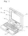
- Fig. 1 is a perspective view of a conventional portable computer with an openable display body.
- the conventional portable computer 10 comprises a main body 14 and an openable display body 16 coupled to each other.
- the main body 14 typically includes an area for a CPU (not shown) and carries a keyboard 12 on its top surface.
- the openable display body 16 is hinged to the rear edge of the main body 14 and carries display panel 18, such as an LCD (liquid crystal display) panel.
- the display panel 18 is electrically connected to the main body 14 and is designed to display data provided by the main body, such as from an enclosed CPU, according to operation of the keyboard 12 or other input devices.
- Fig. 2 is an exploded perspective view of a portable computer 10, showing the construction of a typical pivot device 30 provided at the junction between the two parts 14 and 16 of the computer 10.
- the display body 16 comprises a front panel 20 and a display housing 22.
- the front panel 20 supports a front portion of the weighty display panel 18, while the display housing 22 supports the rear portion of the display panel 18.
- the main body 14 is provided with a raised or upstanding housing portion 14a at each of the two rear corners, used for accommodating pivot bearings.
- the front panel 20 and the display housing 22 of the display body 16 each have a protrusion 24 at the centre of the respective lower edge.
- the two protrusions having cooperating configurations, are integrated into a single protrusion 24.
- the single protrusion 24 is positioned between the two raised or upstanding housing portions 14a of the main body 14.
- the single protrusion 24 is hinged to the two raised or upstanding housing portions 14a using a pivot device 30 at each end, allowing the display body 16 to pivot open relative to the main body 14.
- each of the pivot devices 30 comprises first and second cooperating pivot means: a pivot bearing 32 and a pivot member 38, which are coupled together.
- the pivot bearings 32 are each firmly retained within each of the raised or upstanding housing portions 14a of the main body 14.
- the pivot members 38 each consist of a flat mounting part with a pivot shaft 34.
- the flat mounting part is provided with a plurality of screw holes 36, through which the corresponding pivot member 38 is attached inside each end of the protrusion 24 of the display housing 22, using screws 40 or other suitable fixing means.
- Each pivot shaft 34 is pivotally inserted into a bore of a corresponding pivot bearing 32, so that the pivot member 38 may rotate relative to the pivot bearing 32.
- a portable computer 10 with the above-described pivot device 30 has a display body 16 hinged to the rear edge of the main body 14 by pivot members 38, which are mounted inside the protrusion 24 of the display housing 22 using a plurality of screws 40, and of which the pivot shafts 34 are pivotally inserted into bores of the pivot bearings 32.
- Fig. 3 is a front elevation view showing a portable computer including the pivot device of Fig. 2.
- the two elements 32 and 38 of the pivot device 30 with fixings 40 are shown in phantom, as placed within the computer.
- the display body 16 is thereby pivotally mounted to the main body 14.
- the distance "g" between supporting points of the pivot member 38 nearest to, and remotest from, the axis of rotation of the pivot shaft 34 is very short.
- the weight of the display body 16, and any torque required to open or close the display body is therefore concentrated onto a small region of the display housing 22 at a position near the axis of rotation of the pivot shaft 34. Every opening or closing action of the display body 16 therefore causes the display housing 22 to be distorted or deformed around this small region.
- This disadvantageously forms a gap between the display panel 18 and the front panel 20. This gap may lead to reduced support for the display panel 18, and in extreme cases could cause the display panel to fall out, or the display housing 22 to break.
- the present invention provides a pivot device for the junction between the openable display body and the main body of a portable computer which more effectively distributes the weight of a display panel. Distortion or deformation of the display housing during opening or closing of the display body is reduced.
- the invention provides a pivot device for portable computers, comprising first and second co-operating pivot means for pivotally connecting a display body and a main body of a computer at a rear edge of the main body, and including a pivot shaft about which the display body may rotate.
- a pivot member depends from a said first pivot means for attachment to the display body.
- the pivot member comprises a lower support part for supporting a lower portion of the display body and a side support part extending radially away from the pivot shaft for supporting a side portion of the display body.
- the lower support part is preferably wider than the side support part.
- the side support part may be provided with at least one latching protrusion which engages and is retained by a retaining part of the side portion of the display body.
- the lower and/or side support parts of the pivot member may be respectively attachable mountable to lower and/or side portions of the display body, using at least one screw.
- the present invention also provides a portable computer, including any such pivot device at a junction between main and display bodies.
- the side support part of the pivot member may engage a retaining part of the side portion of the display body.
- a retaining part may be formed on the side portion of the display body at a position corresponding to the latching protrusion of the side support part, for engaging the latching protrusion.
- the lower and/or side support parts of the pivot member in any such portable computer may be respectively attached to lower and/or side portions of the display body using at least one screw.
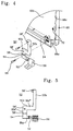
- a pivot device 50 according to the first embodiment of the present invention comprises first and second cooperating pivot means: a pivot bearing 56 and a pivot member, coupled together.
- Pivot bearing 56 is intended to be firmly set in a raised or upstanding housing portion of a computer's main body 70.
- the pivot member consists of a mounting part 54 with a pivot shaft 52.
- the pivot shaft 52 is pivotally inserted into a bore in the pivot bearing 56, allowing the pivot member to rotate relative to the pivot bearing 56.
- the mounting part 54 of the pivot member consists of two parts: a lower support part 50a and a side support part 50b.
- the lower support part 50a extends axially parallel to and radially away from the pivot shaft 52, and is attached to a lower portion 66a of a display housing 66.
- the side support part 50b extends radially away from pivot shaft 52. It is preferably attached to an end of the lower support part 50a remote from the pivot shaft. It is shaped to follow within the configuration of display housing 66 extending along side wall 66c. Support to the side portion of the display housing 66 is provided by the radially extending, side support part 50b of the mounting part 54.
- the pivot shaft 52 may be unitarily formed with either the pivot bearing 56 or the pivot member.
- the pivot shaft may be a separate component, housed in a bore in the pivot member, and a corresponding bore in the pivot bearing.
- the pivot member comprises a lower support part 50a and a side support part 50b, which may be integrally formed.
- the lower support part 50a comprises a first portion 50a' extending primarily in an axial direction with respect to the pivot shaft 52, a second portion 50a'' extending primarily radially with respect to the pivot shaft 52 and a third portion 50a''' extending parallel with and radially spaced from the portion 50a'.
- the parts 50a', 50a'' and 50a''' are coplanar and form a rectangular "C" shape.
- Side support 50b extends from an end portion of portion 50a''' distant from the portion 50a'' in a generally radial direction with respect to the pivot shaft 52 and in the same plane as the lower support part.
- This arrangement allows the pivot bearing 56 to be attached inside a wall of main body 70, while upper support part 50b is mounted inside display housing 62. Typically, the walls of main housing 70 and display housing 62 are aligned.
- the dimensions of the pivot member are adapted so as not to interfere with the location of display panel 64, yet to allow upper support part 50b to extend along, and in proximity with, the side wall 66c of the display housing.
- the pivot shaft 52 is preferably cylindrical, as is the bore in the pivot bearing 26, suitable for being pivotally coupled together.
- the mounting part 54 of the pivot member is provided with a plurality of fastening holes 58, through which the pivot member is attached inside each end of the lower portion of the display housing 66, such as by using one or more screws 68.
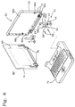
- Fig. 6 is an exploded perspective view of a portable computer 60, showing the pivot device 50 of Fig. 4 provided in computer 60.
- the lower support part 50a of the pivot member is mounted within to the protrusion 24 of the display housing 66.
- a plurality of screws, such as set screws 68 is used.
- the lower support part 50a supports the lower portion 66a of the display housing 66.
- the lower support part 50a is attached to one or more boss 72, formed on the surface 66b of the display housing 66 within the lower portion, using screws 68 through screw holes 58.
- the side support part 50b is attached to one or more further boss 72, formed on the surface 66b of the display housing 66 at the side portion, such as by using screws 68 through screw holes 58'.
- the pivot shaft 52 is pivotally inserted into the bore of the pivot bearing 56, itself to be firmly set into each of raised or upstanding housing portions of the computer's main body 70.
- the lower support part 50a is wider than the side support part 50b.
- the two support parts 50a and 50b respectively have fastening holes 58, 58' at positions corresponding to the bosses 72, for attaching the mounting part to the bosses 72 of the display body 66 using screws 68.
- the lower and side support parts 50a and 50b of the pivot member's mounting part 54 firmly support the lower and side portions of the display housing 66.
- the weight of display panel 18 is thus more effectively distributed away from the axis of rotation of the pivot shaft 52.
- torque and other forces applied during opening and closing of the computer are more effectively distributed away from the axis of rotation of the pivot shaft 52.
- a front panel 74 of the display body 62 has a recess 76 on its interior surface at each position corresponding to a mounting part 54 of a pivot member.
- the recesses 76 are shaped like mounting parts 54, so as to receive the lower and side support parts 50a and 50b.
- the recesses 76 have a depth corresponding to the thickness of the mounting parts 54.
- the display body 62 is not thickened nor enlarged due to the presence of the mounting parts 54.
- Fig. 7 is a front elevation view of a portable computer according to an aspect of the present invention.
- the pivot device 50 of Fig. 6 is shown in place.
- Reference numeral 64 indicates a display panel.
- the computer's display body 62 is hinged to the rear edge of the computer's main body 70 by pivot devices 50.
- the pivot members are mounted inside each end of the display housing 66 using a plurality of screws.
- the pivot shafts 52 are pivotally inserted into a bore of each pivot bearing 56, which is firmly set in each of the raised or upstanding housing portions of the main body 70.
- Lower and side support parts 50a and 50b of the pivot member's mounting part 54 are firmly attached to the lower and side portions of the display housing 66, such as by using a plurality of screws.
- the distance "G1" between supporting points of the pivot member 50 nearest to, and remotest from, the axis of rotation of the pivot shaft 52 is significantly greater than the equivalent distance ("g") of the prior art pivot device 30 of Fig. 3.
- Fig. 8 is a perspective view of a pivot device 100 for portable computers according to a second embodiment of the present invention.
- a pivot device 100 comprises first and second co-operating pivot means: a pivot bearing 56 and a pivot member, coupled together.
- the pivot bearing 56 is to be firmly set in each of raised or upstanding housing portions of the computer's main body 70.
- the pivot member consists of a mounting part 120 and a pivot shaft 110.
- the pivot shaft 110 is pivotally inserted into a bore of the pivot bearing 56. Both pivot shaft 110 and the bore of the pivot bearing are preferably cylindrical, allowing the pivot member to rotate relative to the pivot bearing 56.
- the mounting part 120 of the pivot member consists of two parts: lower support part 130 and side support part 140.
- the lower support part 130 extends axially and radially from the pivot shaft 110, and supports the lower portion 66a of the display housing 66, when in place.
- the side support part 140 radially extends away from the pivot shaft 110. It is shaped to follow with the configuration of the display housing 66.
- the pivot shaft 110 may be unitarily formed with either the pivot bearing 56 or the pivot member.
- the pivot shaft may be a separate component, housed in a bore in the pivot member, and a corresponding bore in the pivot bearing.
- the pivot member comprises a lower support part 130 and a side support part 140, which may be formed integrally.
- the lower support part extends radially and axially from the pivot shaft
- the lower support part 130 comprises a first portion 130' extending primarily in an axial direction with respect to the pivot shaft 52, a second portion 130'' extending primarily radially with respect to the pivot shaft 52 and a third portion 130''' extending parallel with and radially spaced from the portion 130'.
- the portions 130', 130'' and 130''' are coplanar and form a rectangular "C" shape.
- Side support part 140 extends from an end part of portion 130''' distant from the portion 130'', in a plane perpendicular to the plane of lower support part 130, and in a generally radial direction with respect to the pivot shaft 110.
- This arrangement allows the pivot bearing 56 to be attached inside a wall of main body 70, while upper support part 140 is mounted inside display housing 62. Typically, the walls of main housing 70 and display housing 62 are aligned.
- the dimensions of the pivot member are adapted so as not to interfere with the location of display panel 64, yet to allow upper support part 140 to extend along, and in proximity with, the side wall 66c of the display housing.
- the pivot shaft 110 is preferably cylindrical, as is the bore in the pivot bearing 56, suitable for being pivotally coupled together.
- the mounting part 120 of the pivot member is provided with a plurality of fastening holes 58, through which the pivot member is attached inside each end of the lower portion of the display housing 66, such as by using one or more screws 68.
- Upper support part 140 is substantially planar, located in a plane perpendicular to the plane of lower support part 130. Upper support part 140 has an inner face and an outer face. Outer support face carries protrusions 140a, 140b designed to engage other parts of display body 62.
- the protrusions include at least one guide pin 140a, which can fit into corresponding pin accommodating holes 78a in the side wall of a shield plate 78 of the display body 62.
- the side support part 140 preferably also has at least one latching protrusion 140b on its outside wall.
- the pivot bearing 56 is attached inside a wall of main body 70, while upper support part 140 is mounted inside a wall of display housing 62. Typically, the walls of main housing 70 and display housing 62 are aligned.
- Fig. 9 is an exploded perspective view showing the pivot device of Fig. 8 in the display body 62 of a portable computer.
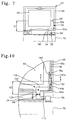
- Fig. 10 is a front view showing the pivot device 100 of Fig. 8.
- the mounting part 120 of the pivot member is mounted inside the protrusion 24 of the display housing 66 using a plurality of screws 68.
- the lower support part 130 of the mounting part 120 is attached to bosses 72, formed on the lower portion 66a of the display housing 66, such as by using screws 68 through screw holes 58.
- the display housing 66 is thereby supported in an axial direction, with respect to the pivot shaft.
- the side support part 140 is fitted to the side wall 66c of the display housing 66, thus supporting the display housing 66 in radial and rotational directions.
- the latching protrusion 140b passes through a cut-out 78b in the shield plate 78, prior to being caught by a corresponding retaining part 150 of the side wall 66c of the display housing 66.
- a different retaining part may be provided within the side portion of the display body 62, but a moulded protrusion on the interior surface of side wall 66c is simplest, and preferred.
- the shield plate 78 of the display body 62 has at least one pin accommodating hole 78a and a cut-out 78b in its side wall.
- the pin accommodating hole 78a allows the guide pin 140a of the side support part 140 to pass through, while the cut-out 78b guides the latching protrusion 140b of the side support part 140.
- Retaining part 150 is provided at a position corresponding to the cut-out 78b. Upon assembly of the display housing 62, the retaining part 150 is brought into engagement with the latching protrusion 140b which passes through the cut-out 78b.
- Guide pins 140a radially support the side portion, while latching protrusion 140b provides rotational support.
- the front panel of the display body 62 has a recess on its interior surface at a position corresponding to each mounting part 120 of each pivot member.
- the recesses have the same configuration as the mounting parts 120 consisting of the lower and side support parts 130 and 140, and have a depth corresponding to the thickness of the mounting part 120.
- the display body 62 is therefore not thickened despite inclusion of the mounting part 120.
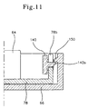
- Fig. 11 is a sectional view taken along the line A-A of Fig. 10, showing the interaction of the latching protrusion 140b with the retaining protrusion 150 of side wall 66c.
- the display body 62 is pivotally attached to the rear edge of the main body 70 by the pivot device of the second embodiment of the invention similarly as for the first embodiment. That is, the mounting part 120 of the pivot member is mounted inside each lower portion 66a of the display housing 66 using one or more screws 68.
- the pivot shaft 110 is pivotally inserted into the bore of the pivot bearing 56, which itself is to be firmly set in each of the raised or upstanding housing portions of the computer main body 70.
- lower support part 130 of the pivot member's mounting part 120 is firmly attached to the lower portion 66a of the display housing 66 using one or more screws 68.
- the latching protrusion 140b of side support part 140 of the mounting part 120 passes through a cut-out 78b in the shield plate 78 of the display body 62 prior to being caught by the retaining part 150 inside the side portion of the display housing 66.
- the guide pins 140a of the side support part 140 are inserted into the pin accommodating holes 78a of the shield plate 78. Therefore, the side support part 140 is brought into engagement with the side wall 66c of the display body 66, supporting the side portion of the display housing 66 in radial and rotational directions.
- the distance "G2" between supporting points of the mounting part 120 nearest to, and remotest from, the axis of rotation of the pivot shaft 110 is significantly greater than the equivalent distance ("g") of the prior art pivot device 30 of Fig. 3.
- the pivot device 50 effectively distributes the weight of the display body 62, containing the weighty display panel 64, over lower and side support parts 50a and 50b of each pivot member.
- the pivot device 50 avoids overloading the pivot shaft 52 of the pivot member by the weight of the display body 62 and avoids distortion or deformation of the display housing 66 during opening or closing actions of the display body 62, even when the display body 62 is equipped with a large-sized display panel 64.
- the side support part 140 of the pivot member is firmly held in the side portion of the display housing 66 which supports the display panel 64.
- the pivot device 100 effectively distributes the weight of the display body 62 and avoids distortion or deformation of the display housing 66 during opening or closing actions of the display body 62 even when the display body 62 is equipped with a large-sized display panel 64.
- the present invention provides a pivot device, containing a pivot member for attachment to lower and side portions of a computer's display housing through lower and side support parts.
- the pivot device effectively distributes the weight of the display body over lower and side support parts. This distribution effectively avoids the pivot shaft of the pivot members being overloaded by the weight of the display body even when the display body is equipped with a large-sized display panel. Distortion or deformation of the display housing during opening or closing actions of the display body is also avoided, by distribution of torque and other forces applied during opening and closing actions.
- Avoidance of distortion of deformation of the display housing during opening or closing actions avoids any gap forming between the display panel and the front panel, avoids any vibrations and fatigue fracture of the pivot member, and improves the strength of the display housing.
- pivot devices for attachment at one corner of main and display bodies of a computer have discussed pivot devices for attachment at one corner of main and display bodies of a computer.
- symmetrical pivot devices will be provided, one at each lower corner of the display body, correspondingly connected to rear corners of main body 70.
Abstract
Description
Claims (10)
- A pivot device (50; 100) for portable computers (60), comprising:first and second co-operating pivot means for pivotally connecting a display body and a main body of a computer at a rear edge of the main body, and including a pivot shaft about which the display body may rotate;a pivot member (54; 130) depending from a said first pivot means for attachment to the display body, said pivot member comprising:a lower support part (50a; 120) for supporting a lower portion (66a) of the display body; anda side support part (50b; 140) extending radially away from the pivot shaft for supporting a side portion of the display body.
- A pivot device according to claim 1, wherein the lower support part is wider than the side support part.
- A pivot device according to claim 1 or claim 2, wherein the side support part is provided with at least one latching protrusion (140b) for engaging a retaining part (150) of the side portion of the display body.
- A pivot device according to any of claims 1-3, wherein the lower support part of the pivot member is attachable to the lower portion of the display body using a screw (68).
- A pivot device according to any of claims 1, 2, 4, wherein the side support part of the pivot member is attachable to the side portion of the display body using a screw (68).
- A portable computer (60), including a pivot device as claimed in any of claims 1-5 provided at a junction between main and display bodies.
- A portable computer according to claim 6, wherein the side support part of the pivot member engages a retaining part of a side portion of the display body.
- A portable computer according to claim 7, wherein the side support part is provided with at least one latching protrusion (140b) and a retaining part (150) is formed on the side wall of the display body at a position corresponding to the latching protrusion of the side support part, for engaging the latching protrusion.
- A portable computer according to any of claims 6-8, wherein the pivot member is mounted to the display body using at least one screw.
- A portable computer according to any of claims 6-9, further comprising a front panel (74) of the display body, the front panel incorporating a recess (76) on an interior surface, to accommodate a pivot member of a pivot device.
Applications Claiming Priority (2)
| Application Number | Priority Date | Filing Date | Title |
|---|---|---|---|
| KR9717227 | 1997-05-06 | ||
| KR1019970017227A KR100233029B1 (en) | 1996-11-13 | 1997-05-06 | A pivot apparatus and a portable computer equipped with the same |
Publications (3)
| Publication Number | Publication Date |
|---|---|
| EP0877313A2 true EP0877313A2 (en) | 1998-11-11 |
| EP0877313A3 EP0877313A3 (en) | 2003-06-04 |
| EP0877313B1 EP0877313B1 (en) | 2005-12-14 |
Family
ID=36848443
Family Applications (1)
| Application Number | Title | Priority Date | Filing Date |
|---|---|---|---|
| EP98303559A Expired - Lifetime EP0877313B1 (en) | 1997-05-06 | 1998-05-06 | Pivot device and portable computer with pivot device |
Country Status (3)
| Country | Link |
|---|---|
| US (1) | US6272006B1 (en) |
| EP (1) | EP0877313B1 (en) |
| DE (1) | DE69832752T2 (en) |
Cited By (1)
| Publication number | Priority date | Publication date | Assignee | Title |
|---|---|---|---|---|
| CN105183080A (en) * | 2015-09-02 | 2015-12-23 | 小米科技有限责任公司 | Terminal with narrow-frame screen |
Families Citing this family (35)
| Publication number | Priority date | Publication date | Assignee | Title |
|---|---|---|---|---|
| US6464195B1 (en) * | 1997-12-04 | 2002-10-15 | Raymond Hildebrandt | Ergonomic mounting for computer screen displays |
| US6501641B1 (en) | 1998-10-23 | 2002-12-31 | Lg. Philips Lcd Co. Ltd. | Portable computer having a flat panel display device |
| JP3538046B2 (en) * | 1998-12-11 | 2004-06-14 | Nec液晶テクノロジー株式会社 | Portable terminal device |
| JP3141869B2 (en) * | 1999-02-15 | 2001-03-07 | 日本電気株式会社 | Mounting structure of liquid crystal module and portable information terminal device equipped with the same |
| KR100322651B1 (en) * | 1999-03-13 | 2002-02-07 | 윤종용 | Display unit and notebook computer using the unit |
| JP4071913B2 (en) * | 1999-12-27 | 2008-04-02 | 三菱電機株式会社 | Liquid crystal display |
| CN1418333A (en) * | 2000-03-15 | 2003-05-14 | 金龙俊 | Computer having plural monitors |
| US6522529B1 (en) * | 2000-05-22 | 2003-02-18 | Vivek R. Huilgol | Rotatable computer display apparatus and method |
| JP3673223B2 (en) * | 2002-01-21 | 2005-07-20 | 株式会社東芝 | Portable information equipment |
| US6788527B2 (en) * | 2002-05-31 | 2004-09-07 | Hewlett-Packard Development Company, L.P. | Tablet computer keyboard and system and method incorporating same |
| US6657856B1 (en) * | 2002-07-08 | 2003-12-02 | Lu Sheng-Nan | Hinge for a notebook computer |
| TW576537U (en) * | 2002-10-04 | 2004-02-11 | Quanta Comp Inc | An open and close test apparatus for panel |
| JP2005165478A (en) * | 2003-11-28 | 2005-06-23 | Toshiba Corp | Electronic device and hinge device for use therewith |
| US7343645B2 (en) * | 2004-04-23 | 2008-03-18 | Asustek Computer Inc. | Electronic apparatus having detachable display and mainframe |
| KR20050109310A (en) * | 2004-05-13 | 2005-11-21 | 삼성전자주식회사 | Display apparatus |
| US7082028B2 (en) * | 2004-07-08 | 2006-07-25 | Swivel It, Inc. | Rotatable computer display apparatus and method |
| US7403377B2 (en) * | 2005-01-20 | 2008-07-22 | Hewlett-Packard Development Company, L.P. | Method of manufacture and an enclosure for a display for an electronic device |
| TWI265769B (en) * | 2005-12-22 | 2006-11-01 | Asustek Comp Inc | Hinge fastening apparatus |
| US7533448B2 (en) * | 2005-12-27 | 2009-05-19 | Jr-Jiun Chern | Hinge |
| CN2909316Y (en) * | 2006-04-28 | 2007-06-06 | 鸿富锦精密工业(深圳)有限公司 | Liquid crystal display |
| JP5040532B2 (en) * | 2007-08-31 | 2012-10-03 | 富士通株式会社 | Electronics |
| CN201035465Y (en) * | 2007-09-12 | 2008-03-12 | 联想(北京)有限公司 | Notebook computer screen and notebook computer |
| US8390997B1 (en) | 2009-10-06 | 2013-03-05 | Brenda Dominy | Portable computer with adjustable monitor |
| JP4724245B2 (en) * | 2009-12-25 | 2011-07-13 | 株式会社東芝 | Electronics |
| US8174827B2 (en) * | 2010-01-29 | 2012-05-08 | Yang Pan | Portable tablet computing device with a low power operation mode as a media player |
| TWI402510B (en) * | 2010-04-07 | 2013-07-21 | Inventec Corp | Testing device |
| US20110279949A1 (en) * | 2010-05-14 | 2011-11-17 | Sony Ericsson Mobile Communications Japan, Inc. | Method of securing hinge, and electronic apparatus |
| TWI447324B (en) * | 2012-03-30 | 2014-08-01 | Azurewave Technologies Inc | Thin-type collapsible foot stand |
| US8860666B2 (en) | 2012-07-03 | 2014-10-14 | Yang Pan | Portable computer with a twistable display |
| CN103853255A (en) * | 2012-12-07 | 2014-06-11 | 鸿富锦精密工业(深圳)有限公司 | Computer case supporting structure |
| JP6323250B2 (en) * | 2014-08-15 | 2018-05-16 | 富士通株式会社 | Electronic device and method for manufacturing electronic device |
| TWI598021B (en) * | 2016-08-31 | 2017-09-01 | 華碩電腦股份有限公司 | Electronic device and hinge assembly thereof |
| JP6643723B2 (en) * | 2017-01-05 | 2020-02-12 | 富士通クライアントコンピューティング株式会社 | Information processing terminal and hinge unit |
| US11092996B2 (en) * | 2019-08-20 | 2021-08-17 | Getac Technology Corporation | Electronic device |
| TWI733621B (en) * | 2020-11-23 | 2021-07-11 | 英業達股份有限公司 | Fixture assembly of electronics device for fixing hinge bracket and method for the same |
Citations (5)
| Publication number | Priority date | Publication date | Assignee | Title |
|---|---|---|---|---|
| US5168426A (en) * | 1991-08-16 | 1992-12-01 | Beaver Computer Corporation | Hinge mechanism for cover panel of portable computer including slide mechanism |
| JPH0617570A (en) * | 1992-06-30 | 1994-01-25 | Kato Electrical Mach Co Ltd | Hinge for tilt feature |
| US5566048A (en) * | 1994-06-02 | 1996-10-15 | Hewlett-Packard Company | Hinge assembly for a device having a display |
| US5636102A (en) * | 1995-09-21 | 1997-06-03 | International Business Machines Corporation | Portable information processing apparatus with hinge for enlarged LCD display |
| US6212067B1 (en) * | 1996-10-21 | 2001-04-03 | Kabushiki Kaisha Toshiba | Portable information apparatus having a display unit comprising a housing and a display contained in the housing |
Family Cites Families (9)
| Publication number | Priority date | Publication date | Assignee | Title |
|---|---|---|---|---|
| US4730364A (en) | 1985-10-29 | 1988-03-15 | Bondwell Holding Ltd. | Data processor flush hinge assembly |
| JPH057629Y2 (en) | 1986-08-29 | 1993-02-25 | ||
| JPH066391Y2 (en) * | 1988-11-30 | 1994-02-16 | 株式会社東芝 | Display opening / closing detection mechanism |
| JP2880729B2 (en) * | 1989-06-23 | 1999-04-12 | 株式会社東芝 | Small electronic equipment |
| US5173837A (en) * | 1990-10-15 | 1992-12-22 | Compaq Computer Corporation | Hinge with two-towed clutch spring for suppressing electromagnetic interference for laptop personal computers |
| JPH04203517A (en) * | 1990-11-29 | 1992-07-24 | Toshiba Corp | Shaft pivoting device |
| KR960006917Y1 (en) * | 1993-11-29 | 1996-08-12 | 삼성전자 주식회사 | Hinge-fixing apparatus of computer |
| US5754395A (en) * | 1995-08-29 | 1998-05-19 | Acer Advanced Labs, Inc. | Ergonomic keyboard for a portable computer which is moveable between two positions |
| JP3521168B2 (en) * | 1996-04-08 | 2004-04-19 | 株式会社東芝 | Portable equipment |
-
1998
- 1998-05-06 DE DE69832752T patent/DE69832752T2/en not_active Expired - Lifetime
- 1998-05-06 US US09/073,059 patent/US6272006B1/en not_active Expired - Lifetime
- 1998-05-06 EP EP98303559A patent/EP0877313B1/en not_active Expired - Lifetime
Patent Citations (5)
| Publication number | Priority date | Publication date | Assignee | Title |
|---|---|---|---|---|
| US5168426A (en) * | 1991-08-16 | 1992-12-01 | Beaver Computer Corporation | Hinge mechanism for cover panel of portable computer including slide mechanism |
| JPH0617570A (en) * | 1992-06-30 | 1994-01-25 | Kato Electrical Mach Co Ltd | Hinge for tilt feature |
| US5566048A (en) * | 1994-06-02 | 1996-10-15 | Hewlett-Packard Company | Hinge assembly for a device having a display |
| US5636102A (en) * | 1995-09-21 | 1997-06-03 | International Business Machines Corporation | Portable information processing apparatus with hinge for enlarged LCD display |
| US6212067B1 (en) * | 1996-10-21 | 2001-04-03 | Kabushiki Kaisha Toshiba | Portable information apparatus having a display unit comprising a housing and a display contained in the housing |
Non-Patent Citations (1)
| Title |
|---|
| PATENT ABSTRACTS OF JAPAN vol. 018, no. 224 (M-1596), 22 April 1994 (1994-04-22) -& JP 06 017570 A (KATO ELECTRICAL MACH. CO. LTD.), 25 January 1994 (1994-01-25) * |
Cited By (1)
| Publication number | Priority date | Publication date | Assignee | Title |
|---|---|---|---|---|
| CN105183080A (en) * | 2015-09-02 | 2015-12-23 | 小米科技有限责任公司 | Terminal with narrow-frame screen |
Also Published As
| Publication number | Publication date |
|---|---|
| EP0877313A3 (en) | 2003-06-04 |
| EP0877313B1 (en) | 2005-12-14 |
| DE69832752D1 (en) | 2006-01-19 |
| DE69832752T2 (en) | 2006-09-07 |
| US6272006B1 (en) | 2001-08-07 |
Similar Documents
| Publication | Publication Date | Title |
|---|---|---|
| EP0877313B1 (en) | Pivot device and portable computer with pivot device | |
| US6191937B1 (en) | Display with gear type hinge | |
| US6064565A (en) | LCD assembly and information processing apparatus | |
| US8387928B2 (en) | Flat panel display including a hinge assembly | |
| US7310222B2 (en) | Flat-panel display mounting system for portable computer | |
| US6498718B1 (en) | Portable computer and method for mounting a flat panel display device thereon | |
| US6525790B1 (en) | Liquid crystal module mounting structure | |
| EP0816973B1 (en) | A notebook personal computer having a speaker cover structure | |
| US6424391B1 (en) | Flat-panel display device | |
| KR100235888B1 (en) | Portable information processing apparatus | |
| US6270046B1 (en) | Apparatus for mounting a switching power supply in a computer system | |
| KR100533224B1 (en) | Flat panel display mounting structure | |
| US7480131B2 (en) | Hinge frame for portable computer and structure for mounting the same | |
| US6076232A (en) | Hinge structure for electronic apparatus | |
| US20020159227A1 (en) | Display device having housing fitted with display panel and electronic apparatus having the display device | |
| US5666266A (en) | Installation/removal structure for a device for an information processing apparatus | |
| KR100944834B1 (en) | Display device having panel display unit | |
| KR100319203B1 (en) | Lcd monitor apparatus | |
| US6411504B2 (en) | Portable computer having latching hooks | |
| KR100233029B1 (en) | A pivot apparatus and a portable computer equipped with the same | |
| US6693795B2 (en) | Notebook type information apparatus having protruding front side portion | |
| JP3356690B2 (en) | Terminal device | |
| EP2112421A2 (en) | Display screen support mechanism | |
| KR100579551B1 (en) | Computer with Flat Panel Display | |
| KR100426681B1 (en) | Portable computer_ |
Legal Events
| Date | Code | Title | Description |
|---|---|---|---|
| PUAI | Public reference made under article 153(3) epc to a published international application that has entered the european phase |
Free format text: ORIGINAL CODE: 0009012 |
|
| 17P | Request for examination filed |
Effective date: 19980514 |
|
| AK | Designated contracting states |
Kind code of ref document: A2 Designated state(s): AT BE CH CY DE DK ES FI FR GB GR IE IT LI LU MC NL PT SE |
|
| AX | Request for extension of the european patent |
Free format text: AL;LT;LV;MK;RO;SI |
|
| PUAL | Search report despatched |
Free format text: ORIGINAL CODE: 0009013 |
|
| AK | Designated contracting states |
Designated state(s): AT BE CH CY DE DK ES FI FR GB GR IE IT LI LU MC NL PT SE |
|
| AX | Request for extension of the european patent |
Extension state: AL LT LV MK RO SI |
|
| AKX | Designation fees paid |
Designated state(s): DE FR GB |
|
| 17Q | First examination report despatched |
Effective date: 20040906 |
|
| GRAP | Despatch of communication of intention to grant a patent |
Free format text: ORIGINAL CODE: EPIDOSNIGR1 |
|
| GRAS | Grant fee paid |
Free format text: ORIGINAL CODE: EPIDOSNIGR3 |
|
| GRAA | (expected) grant |
Free format text: ORIGINAL CODE: 0009210 |
|
| AK | Designated contracting states |
Kind code of ref document: B1 Designated state(s): DE FR GB |
|
| REG | Reference to a national code |
Ref country code: GB Ref legal event code: FG4D |
|
| REF | Corresponds to: |
Ref document number: 69832752 Country of ref document: DE Date of ref document: 20060119 Kind code of ref document: P |
|
| ET | Fr: translation filed | ||
| PLBE | No opposition filed within time limit |
Free format text: ORIGINAL CODE: 0009261 |
|
| STAA | Information on the status of an ep patent application or granted ep patent |
Free format text: STATUS: NO OPPOSITION FILED WITHIN TIME LIMIT |
|
| 26N | No opposition filed |
Effective date: 20060915 |
|
| REG | Reference to a national code |
Ref country code: GB Ref legal event code: 732E |
|
| REG | Reference to a national code |
Ref country code: FR Ref legal event code: TP |
|
| REG | Reference to a national code |
Ref country code: FR Ref legal event code: PLFP Year of fee payment: 19 |
|
| REG | Reference to a national code |
Ref country code: FR Ref legal event code: PLFP Year of fee payment: 20 |
|
| PGFP | Annual fee paid to national office [announced via postgrant information from national office to epo] |
Ref country code: DE Payment date: 20170531 Year of fee payment: 20 Ref country code: GB Payment date: 20170426 Year of fee payment: 20 Ref country code: FR Payment date: 20170418 Year of fee payment: 20 |
|
| REG | Reference to a national code |
Ref country code: DE Ref legal event code: R071 Ref document number: 69832752 Country of ref document: DE |
|
| REG | Reference to a national code |
Ref country code: GB Ref legal event code: PE20 Expiry date: 20180505 |
|
| PG25 | Lapsed in a contracting state [announced via postgrant information from national office to epo] |
Ref country code: GB Free format text: LAPSE BECAUSE OF EXPIRATION OF PROTECTION Effective date: 20180505 |