EP0877276A2 - Adjustable eyeglasses frame with interchangeable lenses - Google Patents
Adjustable eyeglasses frame with interchangeable lenses Download PDFInfo
- Publication number
- EP0877276A2 EP0877276A2 EP98830253A EP98830253A EP0877276A2 EP 0877276 A2 EP0877276 A2 EP 0877276A2 EP 98830253 A EP98830253 A EP 98830253A EP 98830253 A EP98830253 A EP 98830253A EP 0877276 A2 EP0877276 A2 EP 0877276A2
- Authority
- EP
- European Patent Office
- Prior art keywords
- lens
- bearing
- front element
- eyeglasses frame
- supports
- Prior art date
- Legal status (The legal status is an assumption and is not a legal conclusion. Google has not performed a legal analysis and makes no representation as to the accuracy of the status listed.)
- Withdrawn
Links
- 239000000463 material Substances 0.000 claims abstract description 8
- 230000007935 neutral effect Effects 0.000 claims abstract description 7
- 229920003023 plastic Polymers 0.000 claims abstract description 6
- 230000008878 coupling Effects 0.000 claims description 5
- 238000010168 coupling process Methods 0.000 claims description 5
- 238000005859 coupling reaction Methods 0.000 claims description 5
- 125000006850 spacer group Chemical group 0.000 claims description 4
- 230000007547 defect Effects 0.000 description 10
- 230000000694 effects Effects 0.000 description 7
- 238000005259 measurement Methods 0.000 description 6
- 238000012360 testing method Methods 0.000 description 6
- 230000003287 optical effect Effects 0.000 description 4
- 238000012937 correction Methods 0.000 description 2
- 238000011156 evaluation Methods 0.000 description 2
- 238000003780 insertion Methods 0.000 description 1
- 230000037431 insertion Effects 0.000 description 1
- 239000002184 metal Substances 0.000 description 1
- 238000000034 method Methods 0.000 description 1
- 238000012986 modification Methods 0.000 description 1
- 230000004048 modification Effects 0.000 description 1
- 230000008447 perception Effects 0.000 description 1
Images
Classifications
-
- G—PHYSICS
- G02—OPTICS
- G02C—SPECTACLES; SUNGLASSES OR GOGGLES INSOFAR AS THEY HAVE THE SAME FEATURES AS SPECTACLES; CONTACT LENSES
- G02C5/00—Constructions of non-optical parts
- G02C5/14—Side-members
- G02C5/146—Side-members having special front end
-
- G—PHYSICS
- G02—OPTICS
- G02C—SPECTACLES; SUNGLASSES OR GOGGLES INSOFAR AS THEY HAVE THE SAME FEATURES AS SPECTACLES; CONTACT LENSES
- G02C5/00—Constructions of non-optical parts
- G02C5/02—Bridges; Browbars; Intermediate bars
- G02C5/04—Bridges; Browbars; Intermediate bars with adjustable means
- G02C5/045—Bridges; Browbars; Intermediate bars with adjustable means for varying the horizontal distance of the lenses
-
- G—PHYSICS
- G02—OPTICS
- G02C—SPECTACLES; SUNGLASSES OR GOGGLES INSOFAR AS THEY HAVE THE SAME FEATURES AS SPECTACLES; CONTACT LENSES
- G02C5/00—Constructions of non-optical parts
- G02C5/14—Side-members
- G02C5/20—Side-members adjustable, e.g. telescopic
-
- G—PHYSICS
- G02—OPTICS
- G02C—SPECTACLES; SUNGLASSES OR GOGGLES INSOFAR AS THEY HAVE THE SAME FEATURES AS SPECTACLES; CONTACT LENSES
- G02C2200/00—Generic mechanical aspects applicable to one or more of the groups G02C1/00 - G02C5/00 and G02C9/00 - G02C13/00 and their subgroups
- G02C2200/08—Modular frames, easily exchangeable frame parts and lenses
Definitions
- the present invention relates to an eyeglasses frame viewer.
- the invention concerns a viewer of the above kind, transparent and conformable to any kind of user, able to allow to the user to try on a frame substantially without perceiving the presence of said viewer, making a substantial correction of any view defect.
- Procedure presently followed from the perception of the defect up to the purchase of view eyeglasses first of all provides that the subject is subjected to a measurement of said view defect with an oculistic centre or with a optical shop. Said measurement is carried out by sophisticated test eyeglasses, of the front portion of which graduated corrective lenses are inserted, and it is eventually preceded by a first approximation computerised revelation of the kind and of the grade of the defect.
- test eyeglasses which are usually metallic, provides a bulky and bulky frame, on the front element of which even more than one lens for each eye can be introduced, and a rather high number of test corrective graduated lenses, said lenses being contoured by a plastic or metal rigid support, on which a projecting lug allowing the handling of the same lens is provided, the graduation of the lens being engraved on said lug.
- the subject Following said measurement of the view defect, the subject must choose a frame with the optical shop on which the corrective lenses must be applied, suitable shaped to conform to the chosen frame.
- the only alternative given to the person is to interpose the test graduated corrective lenses of the measurement eyeglasses between the test frame and the eyes, manually keeping them in position, preferably with the help of the optician.
- the client is prevented from correctly evaluating the aesthetical effect, which is intrinsically subjective, of the frame to be bought and is obliged to choose following the advise of the optician or of another reliable person.
- the object of the present invention is that of allowing to the client of an optician shop to can see in a sufficient correct way, and specifically to be able to try on a frame substantially without perceiving the presence of any other object, personally evaluating the aesthetical effect of said frame.
- a eyeglasses frame viewer characterised in that it comprises a structure and a series of corrective and/or neutral lenses, each of them provided with a lens-bearing rim, said structure being comprised of a front element and two lateral rods, adjustable in length, coupled at one end of said front element in such a way to be able to adjust their distance with respect to the barycentre of the same front element, said front element providing two supports on which said lenses with lens-bearing rim are coupled, movable along said front element, said structure and said lens-bearing rims being realised by a transparent plastic material, preferably having a high friction coefficient.
- each one of said lateral rods can provide a central tubular element and two end tubular elements, said central tubular element being telescopically coupled with said two end tubular elements, an end tubular element, coupled at the corresponding end of said front element, being shaped in such a way to substantially bend at 90° along the horizontal plane, the other end tubular element preferably having the end not cooperating with the other tubular elements slightly curved.
- said central tubular element can be also rotatably coupled with said two end tubular elements.
- said tubular elements can provide screws for the reciprocal fixing of the tubular elements.
- said coupling of each of said rods with said front element can provide a spacer, rigidly coupled at the end of said front element, upon which the respective rod is slidably coupled.
- said two supports on which said lenses provided with lens-bearing rim couple have a cylindrical shape and provide a cylindrical through hole, parallel with respect to its axis and rotatably and slidably coupled with said front element.
- a projection can be provided on said lens-bearing rim, in such a way to insert into a corresponding seat provided on said supports, said projection being preferably cylindrically shaped, with the axis substantially parallel with respect to the plane of the lens-bearing rim and perpendicular to the axis of the lens-bearing rim, in such a way to be slidably and rotatably coupled with its seat.
- said lens-bearing rims provide a flat region, preferably opposed with respect to said projection, along the lateral surface, upon which the value of the graduation of the relevant corrective and/or neutral lens is engraved.
- the viewer can provide two lens-supports for the superimposition of more than one corrective lens, realised by the same material of said structure and of said lens-bearing rims, and coupable with said supports provided on the front element, which preferably provide a housing seat for two superimposed lens-bearing rims.
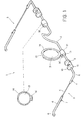
- the viewer for eyeglasses frames comprises a structure 1, comprised of a front element 2, anatomically shaped to rest on the nose of the wearer, and of two lateral rods.
- the rods 3 comprise a central tubular element 4 and two end tubular elements 5 and 6.
- Said central tubular element 4 is telescopically and rotatably coupled with said two end tubular elements 5 and 6.
- Said end tubular elements 5 and 6 each provide a screw 7 for the fixing of said central tubular element 4.
- the end tubular element 5, coupled with said front element, is shaped in such a way to bend substantially for 90° along a substantially horizontal plane.
- the other end tubular element 6 has the end 8 not interacting with the central tubular element slightly curved to anatomically conform above the ear in the same way of the known eyeglasses rods.
- said central tubular element 4 and said end tubular element 6 are rotatably coupled, said end 8 can rest within the ear in case it is necessary, such as in case at the same time of the viewer an eyeglasses frame to be tried on is worn, and the presence of two rods on the ear is not tolerated.
- the end tubular element 5 couples with said front element 2 by a spacer 9, rigidly coupled at the end of said front element 2.
- Said spacer 9 ends with a circular disc 10, parallel with respect to the symmetry plane of said front element 2, providing a circular through hole 11, having its axis parallel with respect to the axis of said disc 10, the section of which corresponds to the section of the coupled end tubular element 5.
- said end tubular element 5 is adjustably introduced within said hole 10. This allows to adjust the distance between the relevant rod 3 and the barycentre of said front element 2, allowing to the viewer to conform to different sizes of the face. Furthermore, by this kind of solution, rod 3 is rotatable with respect to the plane individuated by the axis of the other rod and the front element 2, allowing to the viewer to conform to different anatomical shapes.
- Said front element 2 provides two supports 12, movable along said front element 2, to allow to the viewer to conform to different inter-pupillary distances.
- Lenses 13 provided with lens-bearing rim 14 are coupled on said supports 12.
- Said two supports 12 are cylindrical and provide a cylindrical through hole 15, parallel with respect to its axis, rotatably coupled with said front element 2.
- Said lens-bearing rims 14 provide a lower cylindrical projection 14' to be inserted into a corresponding seat 16 on said supports 12, and in such a way to be slidably and rotatably coupled with said seat.
- Said lens-bearing rims 14 provide along the lateral surface a flat zone 17, opposed with respect to said projection 15, on which the value of the graduation of the relevant corrective and/or neutral lens 13 is engraved.
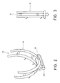
- the viewer further comprises tow lens-bearing supports 18 (see figures 2 and 3), for the superimposition of two corrective lenses 13 into a housing seat 19, providing a lower cylindrical projection 20 for the coupling with the supports 12 similar to the projection 14' of the lens-bearing rims 14.
- said seat 19 provides, in correspondence of said projection 20, a flat zone 21 upon which the zones 17 of the lens-bearing rims 14 of the two lenses 13 which are superimposed on the lens-bearing support 18 rest .
- said lens-bearing rims 14 and said lens-bearing supports 18 are made up of transparent and high friction coefficient plastic material. This prevents that the various elements of the viewer reciprocally coupled move from their positions without an external intervention.
- the viewer according to the invention can be advantageously used with an optical centre to substantially correct the view defects of the clients, allowing them to try on frames without corrective lenses, wearing them contemporaneously to the viewer.
Landscapes
- Physics & Mathematics (AREA)
- Health & Medical Sciences (AREA)
- General Physics & Mathematics (AREA)
- Ophthalmology & Optometry (AREA)
- Optics & Photonics (AREA)
- Nitrogen And Oxygen Or Sulfur-Condensed Heterocyclic Ring Systems (AREA)
- Casting Or Compression Moulding Of Plastics Or The Like (AREA)
- Eyeglasses (AREA)
Abstract
Description
Claims (12)
- Eyeglasses frame viewer characterised in that it comprises a structure and a series of corrective and/or neutral lenses, each of them provided with a lens-bearing rim, said structure being comprised of a front element and two lateral rods, adjustable in length, coupled at one end of said front element in such a way to be able to be able to adjust their distance with respect to the barycentre of the same front element, said front element providing two supports on which said lenses wit lens-bearing rim are coupled, movable along said front element, said structure and said lens-bearing rims being realised by a transparent plastic material, preferably having a high friction coefficient.
- Eyeglasses frame viewer according to claim 1, characterised in that each one of said lateral rods can provide a central tubular element and two end tubular elements, said central tubular element being telescopically coupled with said two end tubular elements, an end tubular element, coupled at the corresponding end of said front element, being shaped in such a way to substantially bend at 90° along the horizontal plane, the other end tubular element preferably having the end not cooperating with the other tubular elements slightly curved.
- Eyeglasses frame viewer according to claim 2, characterised in that said central tubular element is rotatably coupled with said two end tubular elements.
- Eyeglasses frame viewer according to claim 1 or 2, characterised in that screws are provided for the reciprocal fixing of the tubular elements.
- Eyeglasses frame viewer according to one of the preceding claims, characterised in that said coupling of each of said rods with said front element provides a spacer, rigidly coupled at the end of said front element, upon which the respective rod is slidably coupled.
- Eyeglasses frame viewer according to one of the preceding claims, characterised in that said two supports on which said lenses provided with lens-bearing rim couple, have a cylindrical shape and provide a cylindrical through hole, parallel with respect to its axis and rotatably and slidably coupled with said front element.
- Eyeglasses frame viewer according to one of the preceding claims, characterised in that said coupling between each of said two supports and said lenses provided with lens-bearing rim, a projection is provided on said lens-bearing rim, in such a way to insert into a corresponding seat provided on said supports.
- Eyeglasses frame viewer according to claim 7, characterised in that said projection is cylindrically shaped, with the axis substantially parallel with respect to the plane of the lens-bearing rim and perpendicular to the axis of the lens-bearing rim, in such a way to be slidably and rotatably coupled with its seat.
- Eyeglasses frame viewer according to claim 7 or 8, characterised in that said lens-bearing rims provide a flat region, preferably opposed with respect to said projection, upon which the value of the graduation of the relevant corrective and/or neutral lens is engraved.
- Eyeglasses frame viewer according to one of the preceding claims, characterised in that it provides two lens-supports for the superimposition of more than one corrective and/or neutral lens, realised by the same material of said structure and of said lens-bearing rims, and coupable with said supports provided on the front element.
- Eyeglasses frame viewer according to claim 10, characterised in that said lens-bearing supports provide a housing seat for two superimposed lens-bearing rims.
- Eyeglasses frame viewer according to one of the preceding claims, characterised in that said transparent plastic material by which said structure, said lens-bearing rims and said lens-bearing supports, has a high friction coefficient.
Applications Claiming Priority (2)
| Application Number | Priority Date | Filing Date | Title |
|---|---|---|---|
| ITRM970274 | 1997-05-09 | ||
| IT97RM000274A IT1290617B1 (en) | 1997-05-09 | 1997-05-09 | VIEWER FOR FRAMES |
Publications (2)
| Publication Number | Publication Date |
|---|---|
| EP0877276A2 true EP0877276A2 (en) | 1998-11-11 |
| EP0877276A3 EP0877276A3 (en) | 1999-08-18 |
Family
ID=11405060
Family Applications (1)
| Application Number | Title | Priority Date | Filing Date |
|---|---|---|---|
| EP98830253A Withdrawn EP0877276A3 (en) | 1997-05-09 | 1998-04-27 | Adjustable eyeglasses frame with interchangeable lenses |
Country Status (2)
| Country | Link |
|---|---|
| EP (1) | EP0877276A3 (en) |
| IT (1) | IT1290617B1 (en) |
Cited By (2)
| Publication number | Priority date | Publication date | Assignee | Title |
|---|---|---|---|---|
| WO2009047819A1 (en) * | 2007-10-08 | 2009-04-16 | Zhi Jiang | Frames for eyewear and method of production |
| WO2013030565A1 (en) * | 2011-08-30 | 2013-03-07 | Snelgrove John | Spectacles |
Citations (6)
| Publication number | Priority date | Publication date | Assignee | Title |
|---|---|---|---|---|
| US1528192A (en) * | 1923-03-23 | 1925-03-03 | Benjamin E Brierton | Optical method and instrument |
| US4154513A (en) * | 1976-07-22 | 1979-05-15 | Top-Tex, Inc. | Sunbather's eye protectors |
| JPS59201018A (en) * | 1983-04-28 | 1984-11-14 | Sanriibu Megane Kk | Temple length adjusting device of spectacles |
| CH676887A5 (en) * | 1988-11-11 | 1991-03-15 | Baumann & Co G | |
| WO1992019149A1 (en) * | 1991-04-25 | 1992-11-12 | Rudolf Baumann | Binocular device for determination of refraction |
| US5742375A (en) * | 1996-05-24 | 1998-04-21 | Nikon, Inc. | Head mounted lens support |
-
1997
- 1997-05-09 IT IT97RM000274A patent/IT1290617B1/en active IP Right Grant
-
1998
- 1998-04-27 EP EP98830253A patent/EP0877276A3/en not_active Withdrawn
Patent Citations (6)
| Publication number | Priority date | Publication date | Assignee | Title |
|---|---|---|---|---|
| US1528192A (en) * | 1923-03-23 | 1925-03-03 | Benjamin E Brierton | Optical method and instrument |
| US4154513A (en) * | 1976-07-22 | 1979-05-15 | Top-Tex, Inc. | Sunbather's eye protectors |
| JPS59201018A (en) * | 1983-04-28 | 1984-11-14 | Sanriibu Megane Kk | Temple length adjusting device of spectacles |
| CH676887A5 (en) * | 1988-11-11 | 1991-03-15 | Baumann & Co G | |
| WO1992019149A1 (en) * | 1991-04-25 | 1992-11-12 | Rudolf Baumann | Binocular device for determination of refraction |
| US5742375A (en) * | 1996-05-24 | 1998-04-21 | Nikon, Inc. | Head mounted lens support |
Non-Patent Citations (1)
| Title |
|---|
| PATENT ABSTRACTS OF JAPAN vol. 009, no. 068 (P-344), 28 March 1985 & JP 59 201018 A (SANRIIBU MEGANE KK), 14 November 1984 * |
Cited By (2)
| Publication number | Priority date | Publication date | Assignee | Title |
|---|---|---|---|---|
| WO2009047819A1 (en) * | 2007-10-08 | 2009-04-16 | Zhi Jiang | Frames for eyewear and method of production |
| WO2013030565A1 (en) * | 2011-08-30 | 2013-03-07 | Snelgrove John | Spectacles |
Also Published As
| Publication number | Publication date |
|---|---|
| IT1290617B1 (en) | 1998-12-10 |
| ITRM970274A0 (en) | 1997-05-09 |
| ITRM970274A1 (en) | 1998-11-09 |
| EP0877276A3 (en) | 1999-08-18 |
Similar Documents
| Publication | Publication Date | Title |
|---|---|---|
| WO2009081898A1 (en) | Measurement tool for eyeglasses | |
| BR9806075A (en) | Lenses and glasses with lenses. | |
| US3758202A (en) | Eyeglass frames | |
| CA2360806C (en) | Makeup eyeglasses | |
| JPS5924824A (en) | Multifocus glasses frame | |
| CN1007460B (en) | Sehhilfsgeraet, insbesondere lesehilfsgeraet | |
| US6183081B1 (en) | Kit providing independent right and left eyeglass lenses with side frames and method for assembly thereof | |
| EP0877276A2 (en) | Adjustable eyeglasses frame with interchangeable lenses | |
| KR101420157B1 (en) | A Device of Varying Focus of Lens, and Glasses Having the Same | |
| JPS6251445B2 (en) | ||
| JPH0469763B2 (en) | ||
| US20090231544A1 (en) | Affordable eyeglass fitting method and system | |
| KR101760434B1 (en) | The measurement apparatus of sight | |
| JPH0133045Y2 (en) | ||
| JP2002244088A (en) | Simple spectacles for correcting position | |
| US3074397A (en) | Spectacles for the correction of visual defects, such as especially of onesided weakness of vision | |
| KR20200000886U (en) | Glasses for determining interpupillary distance suitable for frame style and bridge length | |
| CN218272952U (en) | Optometry and light testing glasses | |
| WO2000070387A1 (en) | Eyewear assembly and method for obtaining the same | |
| JPH0238261Y2 (en) | ||
| CN215305765U (en) | Digital high-precision glasses manufacturing and producing device | |
| JP2502834B2 (en) | Eyeglass lenses and eyeglasses | |
| US1422303A (en) | Max poser | |
| JPH06160782A (en) | Spectacles for fitting progressive focusing lens | |
| JPH0137604Y2 (en) |
Legal Events
| Date | Code | Title | Description |
|---|---|---|---|
| PUAI | Public reference made under article 153(3) epc to a published international application that has entered the european phase |
Free format text: ORIGINAL CODE: 0009012 |
|
| AK | Designated contracting states |
Kind code of ref document: A2 Designated state(s): AT BE CH CY DE DK ES FI FR GB GR IE IT LI LU MC NL PT SE |
|
| AX | Request for extension of the european patent |
Free format text: AL;LT;LV;MK;RO;SI |
|
| PUAL | Search report despatched |
Free format text: ORIGINAL CODE: 0009013 |
|
| AK | Designated contracting states |
Kind code of ref document: A3 Designated state(s): AT BE CH CY DE DK ES FI FR GB GR IE IT LI LU MC NL PT SE |
|
| AX | Request for extension of the european patent |
Free format text: AL;LT;LV;MK;RO;SI |
|
| AKX | Designation fees paid | ||
| REG | Reference to a national code |
Ref country code: DE Ref legal event code: 8566 |
|
| STAA | Information on the status of an ep patent application or granted ep patent |
Free format text: STATUS: THE APPLICATION IS DEEMED TO BE WITHDRAWN |
|
| 18D | Application deemed to be withdrawn |
Effective date: 20000221 |