EP0876897A2 - Cross head extruder die - Google Patents
Cross head extruder die Download PDFInfo
- Publication number
- EP0876897A2 EP0876897A2 EP98103204A EP98103204A EP0876897A2 EP 0876897 A2 EP0876897 A2 EP 0876897A2 EP 98103204 A EP98103204 A EP 98103204A EP 98103204 A EP98103204 A EP 98103204A EP 0876897 A2 EP0876897 A2 EP 0876897A2
- Authority
- EP
- European Patent Office
- Prior art keywords
- housing
- crosshead
- ring
- passage
- crosshead according
- Prior art date
- Legal status (The legal status is an assumption and is not a legal conclusion. Google has not performed a legal analysis and makes no representation as to the accuracy of the status listed.)
- Withdrawn
Links
Images
Classifications
-
- B—PERFORMING OPERATIONS; TRANSPORTING
- B29—WORKING OF PLASTICS; WORKING OF SUBSTANCES IN A PLASTIC STATE IN GENERAL
- B29C—SHAPING OR JOINING OF PLASTICS; SHAPING OF MATERIAL IN A PLASTIC STATE, NOT OTHERWISE PROVIDED FOR; AFTER-TREATMENT OF THE SHAPED PRODUCTS, e.g. REPAIRING
- B29C48/00—Extrusion moulding, i.e. expressing the moulding material through a die or nozzle which imparts the desired form; Apparatus therefor
- B29C48/25—Component parts, details or accessories; Auxiliary operations
- B29C48/30—Extrusion nozzles or dies
- B29C48/32—Extrusion nozzles or dies with annular openings, e.g. for forming tubular articles
- B29C48/34—Cross-head annular extrusion nozzles, i.e. for simultaneously receiving moulding material and the preform to be coated
-
- B—PERFORMING OPERATIONS; TRANSPORTING
- B29—WORKING OF PLASTICS; WORKING OF SUBSTANCES IN A PLASTIC STATE IN GENERAL
- B29C—SHAPING OR JOINING OF PLASTICS; SHAPING OF MATERIAL IN A PLASTIC STATE, NOT OTHERWISE PROVIDED FOR; AFTER-TREATMENT OF THE SHAPED PRODUCTS, e.g. REPAIRING
- B29C48/00—Extrusion moulding, i.e. expressing the moulding material through a die or nozzle which imparts the desired form; Apparatus therefor
- B29C48/03—Extrusion moulding, i.e. expressing the moulding material through a die or nozzle which imparts the desired form; Apparatus therefor characterised by the shape of the extruded material at extrusion
- B29C48/09—Articles with cross-sections having partially or fully enclosed cavities, e.g. pipes or channels
-
- B—PERFORMING OPERATIONS; TRANSPORTING
- B29—WORKING OF PLASTICS; WORKING OF SUBSTANCES IN A PLASTIC STATE IN GENERAL
- B29C—SHAPING OR JOINING OF PLASTICS; SHAPING OF MATERIAL IN A PLASTIC STATE, NOT OTHERWISE PROVIDED FOR; AFTER-TREATMENT OF THE SHAPED PRODUCTS, e.g. REPAIRING
- B29C48/00—Extrusion moulding, i.e. expressing the moulding material through a die or nozzle which imparts the desired form; Apparatus therefor
- B29C48/25—Component parts, details or accessories; Auxiliary operations
- B29C48/256—Exchangeable extruder parts
- B29C48/2562—Mounting or handling of the die
Definitions
- the invention relates to a crosshead of an extrusion system, consisting of one to an extruder to be built housing, which has a inside Feed ring channel receives one arranged in the housing and at an angle to the direction of extrusion of the extruder arranged passage for feeding a with the extrudate to encase the product, which houses a distributor inside and which at the exit with annular, the extrudate flow tapered outer forming tools is interchangeable on the front of the housing are attached, the passage of one end conical guide nipple is surrounded, the outside is also the inner mold.
- the direction of extrusion transverse or under at an angle to the extrusion direction of the upstream Extruder runs.
- the passage for the Feeding a product to be coated with the extrudate can be centric or eccentric in the spray head housing be arranged.
- Such crossheads are available in different embodiments. They have in common that their housing from two relatively elongated nested Components exist, of which the interior is the passage for feeding the product to be encased and usually has a conical outer surface, while the inside of the outer component mostly is also conical, both conical Surfaces must be completely identical in their design, around in the assembled state of the crosshead to serve as a seal. In at least flow paths are one of these two conical surfaces milled for the extrudate, to be replaced by a opening approximately in the center of the crosshead the wall of the outer housing part in the mentioned Extrudate flow paths of the crosshead evenly around the central passage distribute and in this way a (sheathing) Generate hose. This works with sufficient Overall length and the use of complex distributor contours and adjustment means easily, so that such crossheads probably everywhere in the relevant industry be used.
- crossheads are not cheap to manufacture, in particular requires the manufacture of the two mostly conical or cylindrical sealing surfaces high accuracy.
- the formation of the is also complex worked into at least one inner surface Flow paths, because in addition to the extrudate distribution the essential part into the tube shape at the same time the shaping work takes place.
- the invention avoids the disadvantages of the prior art Technology. It is the object of the invention with simple Short, compact and compact Crosshead to create the light and quickly without disassembling its individual components cleaning is quick and easy to adjust and the distribution and shaping of the extrudate flow reworking surfaces without problems and have the possibility of changing extrudates or wear can be easily replaced.
- the invention is that the outer dies an inherently coherent structural Form unit which is attached to the housing and as such is degradable from the housing that the in the housing feed ring channel located directly at the parting plane of housing and assembly of the dies is arranged, and that the parting plane between the housing and unit with the central axis of the passage includes an approximate right angle and / or preferably represents a flat surface.
- the work of extrudate distribution and molding are in the narrow area around the parting plane between Housing and the structural unit of the forming tools relocated and there essentially separated from each other executed, the distribution on the front of the housing and the formation in the structural unity of the Forming tools.
- the crosshead is simpler and therefore cheaper producible.
- the flow paths are easier to shape and easier to clean.
- the cleaning work is faster and easier feasible and therefore less time consuming.
- the Downtimes of the spray head and thus also the Extrusion lines are reduced.
- the crosshead has less weight and less Construction volume.
- This crosshead can be designed so that the depth of the feed ring channel (in the direction of extrusion of the crosshead) low compared to his Diameter is. This leads to a shorter design and further facilitated cleaning.
- the exchangeable distributor ring which is the first part of the directly to the Parting plane connecting outer molding tools forms, by means of an adjusting device transverse to Material flow is adjustable.
- the structural Unit of the shaping tools can be pivoted by means of of a joint or slidable in guides on the housing is stored.
- the mouthpiece surrounding the guide nipple is a ring that goes through on its outer circumference arranged displacement tools in its radial Position opposite the guide and inner shaping nipple is held adjustable.
- this crosshead As a particularly useful design of this crosshead it was found that the structural unit of the outer tools from an annular base element with an inward flange whose facing the housing of the crosshead Side of the sliding, on the front of the housing adjacent distribution ring rests and on its other Side the mouthpiece rests that the basic element Tools for radial adjustment and mounting of the radially adjustable distributor ring and mouthpiece carries, and that the base element foldable or axially slidably attached to the housing of the crosshead is.
- This basic element can also have a cross section have an angular or square outer shape.
- This crosshead can also be designed so that the one located centrally or eccentrically in the housing Passage in an additional part designed as a quill is.
- the quill with the the passage located therein is axially adjustable and if necessary is arranged lockable.
- This crosshead can also be designed so that the housing or the sleeve for receiving sealing connection parts for additional media or a vacuum connection is executed.
- This crosshead can also be designed so that the horizontal angle between the extruder axis and Spray head axis deviates from the right angle.
- this crosshead is that the spray head axis is horizontal or lies at an angle to the vertical axis.
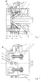
- the crosshead consists of one on the not shown Extruder housing 1, which to this purpose is provided with a flange 3 which on the input side for flanging onto the not shown Extruder barrel or an intermediate flange serves.
- the housing 1 takes on its inside End face an (at least approximated) annular distribution channel 4, which is arranged centrally in the housing 1 and across the extrusion direction of the extruder arranged passage 5 for the supply of a not shown to be encased with the extrudate Product concentrically encloses.
- this distribution channel 4 the one coming from the extruder flows through the Flange 3 extending feed channel 2, which in its course has a kink.
- the extrudate in the subsequent Distribution channel 4, the extrudate is guided so that the passage 5 (initially at a distance) encloses in a ring and thus the beginning of an extrudate tube forms.
- the depth of the annular Distribution channel 4 in the extrusion direction of the crosshead seen) is slight compared to his Diameter.
- shaping tools 7,8,9 which (by holding nut 6) are combined into one unit.
- This assembly 10 is with a hinge 11 on the Housing 1 hinged and by means of connecting screws 13 attached to the housing 1.
- the face lies in the parting plane 17 between the housing 1 and the structural unit 10 of the dies 7,8,9.
- the shaping tools 7, 8, 9 form the outside of the tubular extrudates and thereby reduce the Extrudate tube diameter.
- the inside of this Extrudate tubing is through the outside of a Shaped nipple 12, which is arranged at the end of the passage 5 is.
- the inside of this nipple 12 serves the centering of the introduced through the passage 5, from extrudate hose to encased product.
- the structural unit 10 of the shaping tools 7, 8, 9 consists from an annular or angular or square Basic element 18 with inwardly directed flange 19, at the housing 1 of the crosshead facing Side of the cross direction of flow of the extrudate adjustable, lying on the front side of the housing 1 Distribution ring 7 abuts and on the other Page the mouthpiece 9 rests.
- This mouthpiece 9 is also transverse to the flow direction of the extrudate adjustable, by adjusting screws 16.
- Das Base element 18 carries the elements of the adjustment device (14) for radial adjustment of the distributor ring 7 and the mouthpiece 9.
- the distributor ring 7 can different inner surfaces or inner contours each according to the extrudate to be processed and is therefore easily interchangeable.
- the distributor ring 7 resting on the end face of the housing 1 is of particular importance because this distributor ring 7 essentially shapes and determines the shape of the extrudate hose.
- the distributor ring 7 directly adjoining the parting plane with the surface facing the extrudate stream is an easily replaceable ring. If the flow behavior of another extrudate changes when the extrudate changes or if wear occurs on its surface, it is therefore easy to replace it with a different or new ring.
- This ring is adjustable by means of adjusting screws 14.
- This Ring 15 is with changing flow behavior and / or when signs of wear appear against you new ring interchangeable.
Abstract
Description
Die Erfindung betrifft einen Querspritzkopf einer Extrusionsanlage, bestehend aus einem an einen Extruder anzubauenden Gehäuse, welches in seinem Inneren einen Zuführringkanal aufnimmt, der einen im Gehäuse angeordneten und im Winkel zur Extrusionsrichtung des Extruders angeordneten Durchgang für die Zuführung eines mit dem Extrudat zu ummantelnden Produktes umschließt, welches in seinem Inneren ein Verteilerstück aufnimmt, und welches am Ausgang mit ringförmigen, den Extrudatstrom verjüngenden äußeren Ausformwerkzeugen versehen ist, die an der Stirnseite des Gehäuses auswechselbar befestigt sind, wobei der Durchgang endseitig von einem konischen Führungsnippel umgeben ist, dessen Außenseite gleichzeitig auch das innere Ausformwerkzeug ist.The invention relates to a crosshead of an extrusion system, consisting of one to an extruder to be built housing, which has a inside Feed ring channel receives one arranged in the housing and at an angle to the direction of extrusion of the extruder arranged passage for feeding a with the extrudate to encase the product, which houses a distributor inside and which at the exit with annular, the extrudate flow tapered outer forming tools is interchangeable on the front of the housing are attached, the passage of one end conical guide nipple is surrounded, the outside is also the inner mold.
Dabei ist unter Querspritzkopf ein solcher Spritzkopf verstanden, dessen Extrusionsrichtung quer oder unter einen Winkel schräg zur Extrusionsrichtung des vorgeschalteten Extruders verläuft. Der Durchgang für die Zuführung eines mit dem Extrudat zu ummantelnden Produktes kann zentrisch oder exzentrisch im Spritzkopfgehäuse angeordnet sein.Here is such a spray head under crosshead understood, the direction of extrusion transverse or under at an angle to the extrusion direction of the upstream Extruder runs. The passage for the Feeding a product to be coated with the extrudate can be centric or eccentric in the spray head housing be arranged.
Derartige Querspritzköpfe gibt es in verschiedenen Ausführungsformen. Ihnen ist gemeinsam, daß ihr Gehäuse aus zwei relativ langgestreckten ineinandergesteckten Bauteilen besteht, von denen das Innere den Durchgang für die Zuführung des zu ummantelnden Produktes umschließt und meist eine konische Außenfläche aufweist, während die Innenseite des äußeren Bauteiles meistens ebenfalls konisch gestaltet ist, wobei beide konischen Flächen in ihrer Gestaltung völlig gleich sein müssen, um im zusammengebauten Zustand des Querspritzkopfes aneinander anliegend als Dichtung zu dienen. In zumindest eine dieser beiden konischen Flächen sind Fließwege für das Extrudat eingefräst, um das durch eine etwa mittig im Querspritzkopf angeordnete Durchbrechung der Wandung des äußeren Gehäuseteiles in die genannten Fließwege des Querspritzkopfes eintretende Extrudat gleichmäßig rings um den zentralen Durchgang herum zu verteilen und um auf diese Weise einen (Ummantelungs-) Schlauch zu erzeugen. Das gelingt bei ausreichender Baulänge und der Anwendung aufwendiger Verteilerkonturen und Justiermittel problemlos, so daß solche Querspritzköpfe wohl überall in der einschlägigen Industrie eingesetzt werden.Such crossheads are available in different embodiments. They have in common that their housing from two relatively elongated nested Components exist, of which the interior is the passage for feeding the product to be encased and usually has a conical outer surface, while the inside of the outer component mostly is also conical, both conical Surfaces must be completely identical in their design, around in the assembled state of the crosshead to serve as a seal. In at least flow paths are one of these two conical surfaces milled for the extrudate, to be replaced by a opening approximately in the center of the crosshead the wall of the outer housing part in the mentioned Extrudate flow paths of the crosshead evenly around the central passage distribute and in this way a (sheathing) Generate hose. This works with sufficient Overall length and the use of complex distributor contours and adjustment means easily, so that such crossheads probably everywhere in the relevant industry be used.
An der ausgangsseitigen Stirnseite des Gehäuses sind Arbeitsmittel angebracht, die den abschließenden Teil der Ausformung des hier bereits schlauchförmig vorverteilten Extrudatstromes bewirken. Diese Arbeitsmittel sind vorzugsweise mit Schraubgewinden angebracht. Diese Arbeitsmittel verjüngen den schlauchförmigen Extrudatstrom in seinen Querschnittsdimensionen und leiten ihn in das ebenfalls ringförmige Mundstück über. Are on the output side of the housing Work equipment attached to the final part the shape of the already pre-distributed here Effect extrudate flow. These tools are preferably attached with screw threads. This Working materials rejuvenate the tubular extrudate flow in its cross-sectional dimensions and guide it into the likewise ring-shaped mouthpiece.
Diese Querspritzköpfe sind nicht billig in der Herstellung, insbesondere erfordert die Herstellung der beiden meist konischen oder auch zylindrischen Dichtflächen hohe Genauigkeiten. Aufwendig ist auch die Formung der in zumindest die eine innere Fläche eingearbeiteten Fließwege, weil in diesen neben der Extrudatverteilung in die Schlauchform gleichzeitig der wesentliche Teil der Ausformarbeit stattfindet.These crossheads are not cheap to manufacture, in particular requires the manufacture of the two mostly conical or cylindrical sealing surfaces high accuracy. The formation of the is also complex worked into at least one inner surface Flow paths, because in addition to the extrudate distribution the essential part into the tube shape at the same time the shaping work takes place.
Weitere Probleme bereitet bei diesen Querspritzköpfen die Reinigung bei einem Wechsel der verarbeiteten Kautschukmischung, für die die Teile des Querspritzkopfes auseinanderzunehmen sind, einzeln zu reinigen und dann wieder zusammenzubauen sind. Die Arbeiten der Demontage, Reinigung und der anschließenden Montage erfordern einen erheblichen Aufwand an Zeit, während der der Spritzkopf und meist auch die mit ihm ausgestattete Extrusionsanlage für den Betrieb ausfallen.There are further problems with these crossheads cleaning when changing the processed rubber mixture, for the parts of the crosshead are to be taken apart, cleaned individually and then are to be reassembled. The dismantling work, Cleaning and subsequent assembly required a significant amount of time during which the Spray head and usually also the extrusion system equipped with it fail for operation.
Die Erfindung vermeidet die Nachteile des Standes der Technik. Es ist die Aufgabe der Erfindung, mit einfachen Mitteln einen kurzbauenden, gedrungenen und kompakten Querspritzkopf zu schaffen, der leicht und schnell ohne Demontage seiner einzelnen Bauteile zu reinigen ist, schnell und problemlos zu justieren ist und dessen die Verteilung und Ausformung des Extrudatstromes bewirkenden Flächen problemlos nachzuarbeiten sind und die Möglichkeit in sich bergen, bei Extrudatwechsel oder Verschleiß leicht ausgetauscht zu werden.The invention avoids the disadvantages of the prior art Technology. It is the object of the invention with simple Short, compact and compact Crosshead to create the light and quickly without disassembling its individual components cleaning is quick and easy to adjust and the distribution and shaping of the extrudate flow reworking surfaces without problems and have the possibility of changing extrudates or wear can be easily replaced.
Die Erfindung besteht darin, daß die äußeren Ausformwerkzeuge eine in sich fest zusammenhängende bauliche Einheit bilden, welche am Gehäuse angebracht ist und als solche vom Gehäuse abbaubar ist, daß der im Gehäuse befindliche Zuführringkanal unmittelbar an der Trennebene von Gehäuse und Baueinheit der Ausformwerkzeuge angeordnet ist, und daß die Trennebene zwischen Gehäuse und Baueinheit mit der Mittelachse des Durchganges einen genähert rechten Winkel einschließt und/oder vorzugsweise eine plane Fläche darstellt.The invention is that the outer dies an inherently coherent structural Form unit which is attached to the housing and as such is degradable from the housing that the in the housing feed ring channel located directly at the parting plane of housing and assembly of the dies is arranged, and that the parting plane between the housing and unit with the central axis of the passage includes an approximate right angle and / or preferably represents a flat surface.
Mit dieser einfachen Konstruktion werden überraschenderweise die aufgezeigten Nachteile der bekannten Querspritzköpfe vermieden:With this simple construction, surprisingly the disadvantages of the known crossheads avoided:
Die langgestreckten meist konischen Flächen und die Einarbeitung der Fließkanäle in diese Flächen können ersatzlos entfallen.The elongated mostly conical surfaces and the Incorporation of the flow channels in these areas can omitted without replacement.
Die Arbeiten der Extrudatverteilung und der Ausformung werden in den engen Bereich um die Trennebene zwischen Gehäuse und der baulichen Einheit der Ausformwerkzeuge verlegt und dort im wesentlichen voneinander getrennt ausgeführt, die Verteilung an der Stirnseite des Gehäuses und die Ausformung in der baulichen Einheit der Ausformwerkzeuge.The work of extrudate distribution and molding are in the narrow area around the parting plane between Housing and the structural unit of the forming tools relocated and there essentially separated from each other executed, the distribution on the front of the housing and the formation in the structural unity of the Forming tools.
Der Querspritzkopf ist einfacher und daher preisgünstiger herstellbar.The crosshead is simpler and therefore cheaper producible.
Die Fließwege sind leichter zu formen und leichter zu reinigen.The flow paths are easier to shape and easier to clean.
Die Reinigungsarbeiten sind schneller und leichter durchführbar und damit weniger zeitaufwendig. Die Stillstandszeiten des Spritzkopfes und damit auch der Extrusionsanlage werden damit verringert.The cleaning work is faster and easier feasible and therefore less time consuming. The Downtimes of the spray head and thus also the Extrusion lines are reduced.
Der Querspritzkopf weist geringeres Gewicht und weniger Bauvolumen auf.The crosshead has less weight and less Construction volume.
Dieser Querspritzkopf läßt sich dabei so gestalten, daß die Tiefe des Zuführringkanales (in Extrusionsrichtung des Querspritzkopfes gesehen) gering gegenüber seinem Durchmesser ist. Das führt zu kürzerer Bauform und weiterer erleichterter Reinigung.This crosshead can be designed so that the depth of the feed ring channel (in the direction of extrusion of the crosshead) low compared to his Diameter is. This leads to a shorter design and further facilitated cleaning.
Besonders vorteilhaft ist es, wenn das unmittelbar an die Trennebene anschließende Ausformwerkzeug mit der dem Materialstrom zugekehrten Oberfläche, deren Tangenten vorzugsweise einen stumpfen Winkel einschließen, ein austauschbarer Ring ist. Dieser läßt sich leicht und unabhängig von anderen Bauteilen justieren, er läßt sich ggf. leicht nachbearbeiten und er läßt sich bei Extrudatwechsel oder bei Verschleiß ggf.leicht austauschen.It is particularly advantageous if this occurs immediately the separating plane with the mold surface facing the material flow, its tangents preferably include an obtuse angle, is an interchangeable ring. This is easy and adjust independently of other components, he lets can easily be reworked and he can be Change the extrudate or replace easily if worn.
Dazu ist es vorteilhaft, wenn der austauschbare Verteilerring, der das erste Teil der unmittelbar an die Trennebene anschließenden äusseren Ausformwerkzeuge bildet, mittels einer Justiervorrichtung quer zum Materialstrom einstellbar ist.For this it is advantageous if the exchangeable distributor ring, which is the first part of the directly to the Parting plane connecting outer molding tools forms, by means of an adjusting device transverse to Material flow is adjustable.
Weiter verkürzt es die Maschinenstillstandszeiten, wenn bei diesem Querspritzkopf die bauliche Einheit der äußeren Ausformwerkzeuge mit einer Schnellbefestigungsvorrichtung am Gehäuse befestigt ist. Dann läßt sich die bauliche Einheit der Ausformwerkzeuge leicht und schnell von der Stirnseite des Gehäuses lösen und wieder befestigen.It also shortens machine downtime when the structural unit of this crosshead outer molds with a quick fastening device is attached to the housing. Then you can the structural unity of the molding tools is easy and quickly detach from the front of the case and again fasten.
Dazu ist es dann besonders vorteilhaft, wenn die bauliche Einheit der Ausformwerkzeuge verschwenkbar mittels eines Gelenkes oder verschiebbar in Führungen am Gehäuse gelagert ist.For this purpose, it is particularly advantageous if the structural Unit of the shaping tools can be pivoted by means of of a joint or slidable in guides on the housing is stored.
Die Verarbeitung abrasiver Extrudate bringt es mit sich, daß in und an den Extrudat führenden Kanälen im Inneren des Querspritzkopfes Verschleißerscheinungen auftreten, die den Produktionsvorgang insbesondere dann beeinflussen, wenn sie an den Verteil- und Ausformkanälen auftreten. Um diese in einem solchen Falle schnell auswechseln zu können, ist es von Vorteil, wenn der unmittelbar an die Trennebene anschließende, in der Stirnseite des Gehäuses befindliche Verteilerkanal in einen Ring eingearbeitet ist, welcher in eine stirnseitige Ausnehmung des Gehäuses eingelegt ist. Dieses Auswechseln ist auch für die Änderung bzw. den Wechsel von Fließkonturen von Vorteil.It has the processing of abrasive extrudates that in and on the extrudate channels in Signs of wear inside the crosshead occur which particularly affects the production process affect if they on the distribution and molding channels occur. To do this quickly in such a case To be able to replace it is an advantage if it is immediate adjoining the parting plane in which Distribution channel in front of the housing a ring is incorporated, which in an end Recess of the housing is inserted. This replacement is also for changing or changing Flow contours are an advantage.
Da bei diesem Querspritzkopf die räumliche Zone der Extrudatverteilung und -ausformung meist sehr kurz ist und weil neben dem Extrudatzuführkanal Bauraum für die Anbringung der Ausformwerkzeuge benötigt wird, muß in manchen Fällen die Extrudatzuführung in den Verteilkanal schräg oder parallel zur Extrusionsrichtung des Querspritzkopfes erfolgen. In diesen Fällen ist es von Vorteil, wenn der das Extrudat vom Extruder in den Zuführringkanal führende Zuführungskanal einen Bogen oder einen Knick aufweist und vorzugsweise Enden aufweist, von denen das eine, in den Verteilerkanal führende, genähert parallel zur Achse des Querspritzkopfes, das andere Ende hingegen genähert quer zur Achse des Querspritzkopfes verläuft.Since the spatial zone of this crosshead Extrudate distribution and shaping is usually very short and because in addition to the extrudate feed channel, there is space for the Attachment of the dies is required in in some cases the extrudate feed into the distribution channel obliquely or parallel to the extrusion direction of the Crosshead. In these cases it is from Advantage if the extrudate from the extruder into the feed ring channel leading feed channel an arch or has a kink and preferably has ends, one of which approached the distribution channel parallel to the axis of the crosshead, the other The end, however, approached transversely to the axis of the crosshead runs.
Weiterhin ist es für die Gestaltung dieses Querspritzkopfes von Vorteil, daß in der Baueinheit der äußeren Ausformwerkzeuge das den Führungsnippel umgebende Mundstück ein Ring ist, der durch an seinem äußeren Umfang angeordnete Verschiebewerkzeuge in seiner radialen Stellung gegenüber dem Führungs- und inneren Ausformnippel einstellbar gehalten ist.Furthermore, it is for the design of this crosshead advantageous that in the structural unit of the outer Forming tools the mouthpiece surrounding the guide nipple is a ring that goes through on its outer circumference arranged displacement tools in its radial Position opposite the guide and inner shaping nipple is held adjustable.
Als eine besonders zweckmäßige Bauform dieses Querspritzkopfes wurde gefunden, daß die Baueinheit der äußeren Ausformwerkzeuge aus einem ringförmigen Grundelement mit nach innen gerichtetem Flansch besteht, an dessen dem Gehäuse des Querspritzkopfes zugekehrter Seite der verschiebbare, an der Stirnseite des Gehäuses anliegende Verteilerring anliegt und an dessen anderer Seite das Mundstück anliegt, daß das Grundelement die Werkzeuge zur radialen Verstellung und Halterung des radial verstellbaren Verteilerringes und des Mundstücks trägt, und daß das Grundelement klappbar oder axial verschiebbar am Gehäuse des Querspritzkopfes angebracht ist. Dieses Grundelement kann im Querschnitt auch eine eckige oder quadratische äußere Form haben.As a particularly useful design of this crosshead it was found that the structural unit of the outer tools from an annular base element with an inward flange whose facing the housing of the crosshead Side of the sliding, on the front of the housing adjacent distribution ring rests and on its other Side the mouthpiece rests that the basic element Tools for radial adjustment and mounting of the radially adjustable distributor ring and mouthpiece carries, and that the base element foldable or axially slidably attached to the housing of the crosshead is. This basic element can also have a cross section have an angular or square outer shape.
Dieser Querspritzkopf kann auch so gestaltet sein, daß der zentrisch oder exzentrisch im Gehäuse befindliche Durchgang in einem zusätzlichen Teil als Pinole ausgeführt ist.This crosshead can also be designed so that the one located centrally or eccentrically in the housing Passage in an additional part designed as a quill is.
Dabei kann es zweckmäßig sein, daß die Pinole mit dem darin befindlichen Durchgang axial verstellbar und ggf. feststellbar angeordnet ist.It may be appropriate that the quill with the the passage located therein is axially adjustable and if necessary is arranged lockable.
Es besteht hierbei auch die Möglichkeit, daß das Gehäuse bzw. die Pinole zur Aufnahme auswechselbarer Führungselemente ausgeführt ist.There is also the possibility that the housing or the quill to hold interchangeable guide elements is executed.
Dieser Querspritzkopf kann auch so ausgeführt sein, daß das Gehäuse bzw. die Pinole zur Aufnahme dichtender Anschlußteile für Zusatzmedien oder einen Vakuumanschluß ausgeführt ist.This crosshead can also be designed so that the housing or the sleeve for receiving sealing connection parts for additional media or a vacuum connection is executed.
Dieser Querspritzkopf läßt sich auch so ausführen, daß der horizontale Winkel zwischen Extruderachse und Spritzkopfachse vom rechten Winkel abweicht.This crosshead can also be designed so that the horizontal angle between the extruder axis and Spray head axis deviates from the right angle.
Eine andere Ausführungsmöglichkeit dieses Querspritzkopfes besteht darin, daß die Spritzkopfachse horizontal oder im Winkel bis zur vertikalen Achse liegt.Another possible embodiment of this crosshead is that the spray head axis is horizontal or lies at an angle to the vertical axis.
Das Wesen der Erfindung ist nachstehend anhand eines in
der Zeichnung schematisch dargestellten Ausführungsbeispieles
näher erläutert. Es zeigen:
Der Querspritzkopf besteht aus einem an dem nicht dargestellten
Extruder anzubauenden Gehäuse 1, welches zu
diesem Zweck mit einem Flansch 3 versehen ist, der
eingangsseitig für das Anflanschen an den nicht dargestellten
Extruderzylinder oder einen Zwischenflansch
dient. Das Gehäuse 1 nimmt in seinem Inneren an seiner
Stirnseite einen (zumindest genähert) ringförmigen Verteilerkanal
4 auf, der einen zentrisch im Gehäuse 1 angeordneten
und quer zur Extrusionsrichtung des Extruders
angeordneten Durchgang 5 für die Zuführung eines
nicht dargestellten mit dem Extrudat zu ummantelnden
Produktes konzentrisch umschließt. In diesen Verteilerkanal
4 mündet der vom Extruder kommende, durch den
Flansch 3 verlaufende Zuführungskanal 2, welcher in
seinem Verlauf einen Knick aufweist. in dem anschließenden
Verteilerkanal 4 wird das Extrudat so geführt,
daß es (zunächst mit Abstand) den Durchgang 5
ringförmig umschließt und somit den Anfang eines Extrudatschlauches
bildet. Die Tiefe des ringförmigen
Verteilerkanales 4 (in Extrusionsrichtung des Querspritzkopfes
gesehen) ist gering gegenüber seinem
Durchmesser.The crosshead consists of one on the not shown
Vor der Stirnseite des Gehäuses 1 des Querspritzkopfes
befinden sich Ausformwerkzeuge 7,8,9, die (durch Haltemutter
6) zu einer Baueinheit zusammengefaßt sind.
Diese Baueinheit 10 ist mit einem Gelenk 11 an dem
Gehäuse 1 angelenkt und mittels Verbindungsschrauben 13
am Gehäuse 1 befestigt. Dabei liegt die Stirnseite in
der Trennebene 17 zwischen Gehäuse 1 und der Baueinheit
10 der Ausformwerkzeuge 7,8,9. In front of the front of the
Die Ausformwerkzeuge 7,8,9 formen die Außenseite des
schlauchförmigen Extrudates und verringern dabei den
Durchmesser des Extrudatschlauches. Die Innenseite dieses
Extrudatschlauches wird durch die Außenseite eines
Nippels 12 geformt, der am Ende des Durchganges 5 angeordnet
ist. Dieser Nippel 12 dient mit seiner Innenseite
der Zentrierung des durch den Durchgang 5 eingeführten,
vom Extrudatschlauch zu ummantelnden Produktes.The
Die Baueinheit 10 der Ausformwerkzeuge 7,8,9 besteht
aus einem ringförmigen oder eckigen oder quadratischen
Grundelement 18 mit nach innen gerichtetem Flansch 19,
an dessen dem Gehäuse 1 des Querspritzkopfes zugekehrter
Seite der quer zur Strömungsrichtung des Extrudates
einstellbare, an der Stirnseite des Gehäuses 1 anliegende
Verteilerring 7 anliegt und an dessen anderer
Seite das Mundstück 9 anliegt. Dieses Mundstück 9 ist
ebenfalls quer zur Strömungsrichtung des Extrudates
einstellbar, und zwar durch Justierschrauben 16. Das
Grundelement 18 trägt die Elemente der Justiervorrichtung
(14) zur radialen Verstellung des Verteilerringes
7 und des Mundstücks 9. Der Verteilerring 7 kann
unterschiedliche Innenoberflächen bzw.Innenkonturen je
nach zu verarbeitendem Extrudat aufweisen und ist
deshalb leicht austauschbar.The
Von den ringförmigen Ausformwerkzeugen 7,8,9 der Baueinheit
10 ist der an der Stirnseite des Gehäuses 1 anliegende
Verteilerring 7 von besonderer Bedeutung, weil
dieser Verteilerring 7 die Form des Extrudatschlauches
wesentlich formt und bestimmt. Der unmittelbar an die
Trennebene anschließende Verteilerring 7 mit der dem
Extrudatstrom zugekehrten Oberfläche ist ein leicht
austauschbarer Ring. Bei durch verändertes Strömungsverhalten
eines anderen Extrudates bei Extrudatwechsel
oder bei Auftreten von Verschleiß an seiner Oberfläche
ist er daher leicht durch einen anderen bzw. neuen Ring
zu ersetzen.
Dieser Ring ist mittels Justierschrauben 14 einstellbar
gehaltert.Of the ring-shaped
This ring is adjustable by means of adjusting screws 14.
Der unmittelbar an die die Trennebene 17 bildende
Stirnseite des Gehäuses 1 anschließende, in der Stirnseite
des Gehäuses 1 befindliche Verteilkanal 4 ist in
einen Ring 15 eingearbeitet, welcher in eine stirnseitige
Ausnehmung des Gehäuses 1 eingelegt ist. Dieser
Ring 15 ist bei zu veränderndem Fließverhalten und/oder
bei Auftreten von Verschleißerscheinungen gegen einen
neuen Ring auswechselbar. The one directly at the
- 11
- Gehäusecasing
- 22nd
- ZuführungskanalFeed channel
- 33rd
- Flanschflange
- 44th
- VerteilerkanalDistribution channel
- 55
- DurchgangContinuity
- 66
- HaltemutterHolding nut
- 77
- Ausformwerkzeug (Verteilerring)Forming tool (distributor ring)
- 88th
- Ausformwerkzeug (Grundelement)Forming tool (basic element)
- 99
- Ausformwerkzeug (Mundstück)Forming tool (mouthpiece)
- 1010th
- BaueinheitUnit
- 1111
- Gelenkjoint
- 1212th
- Nippelnipple
- 1313
- VerbindungsschraubeConnecting screw
- 1414
- JustierschraubeAdjusting screw
- 1515
- Ringring
- 1616
- JustierschraubeAdjusting screw
- 1717th
- TrennebeneDividing plane
- 1818th
- GrundelementBasic element
- 1919th
- nach innen gerichteter Flanschinward flange
Claims (12)
wobei der Durchgang endseitig von einem konischen Führungsnippel umgeben ist, dessen Außenseite gleichzeitig auch das innere Ausformwerkzeug ist,
dadurch gekennzeichnet,
the end of the passage being surrounded by a conical guide nipple, the outside of which is also the inner shaping tool,
characterized,
dadurch gekennzeichnet,
characterized,
dadurch gekennzeichnet,
characterized,
dadurch gekennzeichnet,
characterized,
dadurch gekennzeichnet,
characterized,
dadurch gekennzeichnet,
characterized,
dadurch gekennzeichnet,
characterized,
dadurch gekennzeichnet,
characterized,
dadurch gekennzeichnet,
characterized,
dadurch gekennzeichnet,
characterized,
dadurch gekennzeichnet,
characterized,
dadurch gekennzeichnet,
characterized,
Applications Claiming Priority (2)
| Application Number | Priority Date | Filing Date | Title |
|---|---|---|---|
| DE19719220 | 1997-05-07 | ||
| DE19719220A DE19719220C2 (en) | 1997-05-07 | 1997-05-07 | Crosshead of an extrusion line |
Publications (2)
| Publication Number | Publication Date |
|---|---|
| EP0876897A2 true EP0876897A2 (en) | 1998-11-11 |
| EP0876897A3 EP0876897A3 (en) | 2001-10-17 |
Family
ID=7828839
Family Applications (1)
| Application Number | Title | Priority Date | Filing Date |
|---|---|---|---|
| EP98103204A Withdrawn EP0876897A3 (en) | 1997-05-07 | 1998-02-24 | Cross head extruder die |
Country Status (6)
| Country | Link |
|---|---|
| US (1) | US6050801A (en) |
| EP (1) | EP0876897A3 (en) |
| JP (1) | JPH10329193A (en) |
| CZ (1) | CZ122298A3 (en) |
| DE (1) | DE19719220C2 (en) |
| SK (1) | SK54098A3 (en) |
Cited By (2)
| Publication number | Priority date | Publication date | Assignee | Title |
|---|---|---|---|---|
| CN103252883A (en) * | 2012-11-19 | 2013-08-21 | 深圳市沃尔核材股份有限公司 | Cable extruder head |
| RU2532193C1 (en) * | 2013-02-28 | 2014-10-27 | Общество с ограниченной ответственностью "Владимирский инновационно-технологический центр" | Forming draw plate |
Families Citing this family (5)
| Publication number | Priority date | Publication date | Assignee | Title |
|---|---|---|---|---|
| US7329113B2 (en) * | 2004-03-19 | 2008-02-12 | Leseman Steven R | Adjustable extrusion die |
| DE102006053224B4 (en) * | 2006-11-11 | 2015-08-13 | Harburg-Freudenberger Maschinenbau Gmbh | Device for holding matrices |
| US9770859B2 (en) * | 2014-12-18 | 2017-09-26 | The Goodyear Tire & Rubber Company | Apparatus for producing laminated fabric ply strips |
| CN109016445B (en) * | 2018-08-29 | 2023-09-22 | 安徽特思通管路技术有限公司 | Extrusion type inner fluorine outer silicone tube forming die |
| CN109228234A (en) * | 2018-09-29 | 2019-01-18 | 软控股份有限公司 | Cross-head and extruder |
Citations (4)
| Publication number | Priority date | Publication date | Assignee | Title |
|---|---|---|---|---|
| GB950741A (en) * | 1959-06-17 | 1964-02-26 | Whitney Blake Co | Extruding apparatus |
| JPS5929141A (en) * | 1982-08-09 | 1984-02-16 | Sumitomo Electric Ind Ltd | Crosshead for simultaneously extruding two layers |
| EP0534208A1 (en) * | 1991-09-23 | 1993-03-31 | Siemens Aktiengesellschaft | Extrusion head for co-extruding at least two plastic materials |
| DE4344250A1 (en) * | 1993-12-23 | 1995-06-29 | Siemens Ag | Method and device for coating at least one optical waveguide |
Family Cites Families (5)
| Publication number | Priority date | Publication date | Assignee | Title |
|---|---|---|---|---|
| US3304579A (en) * | 1965-03-30 | 1967-02-21 | Jr Thomas Ashworth | Dual hinged side delivery head for extruders |
| JPS51147556A (en) * | 1975-06-13 | 1976-12-17 | Toyo Soda Mfg Co Ltd | Multiilayer rotary circular die |
| US4124346A (en) * | 1976-04-07 | 1978-11-07 | The Goodyear Tire & Rubber Company | Extruder die arrangement |
| US4280801A (en) * | 1979-05-30 | 1981-07-28 | Crompton & Knowles Corporation | Crosshead |
| DE3506257C1 (en) * | 1985-02-22 | 1986-04-30 | Hermann Berstorff Maschinenbau Gmbh, 3000 Hannover | Hinged multiple extrusion head for the production of tread patterns for tire production |
-
1997
- 1997-05-07 DE DE19719220A patent/DE19719220C2/en not_active Expired - Fee Related
-
1998
- 1998-02-24 EP EP98103204A patent/EP0876897A3/en not_active Withdrawn
- 1998-04-22 CZ CZ981222A patent/CZ122298A3/en unknown
- 1998-04-27 SK SK540-98A patent/SK54098A3/en unknown
- 1998-04-30 JP JP10121001A patent/JPH10329193A/en active Pending
- 1998-05-05 US US09/072,714 patent/US6050801A/en not_active Expired - Fee Related
Patent Citations (4)
| Publication number | Priority date | Publication date | Assignee | Title |
|---|---|---|---|---|
| GB950741A (en) * | 1959-06-17 | 1964-02-26 | Whitney Blake Co | Extruding apparatus |
| JPS5929141A (en) * | 1982-08-09 | 1984-02-16 | Sumitomo Electric Ind Ltd | Crosshead for simultaneously extruding two layers |
| EP0534208A1 (en) * | 1991-09-23 | 1993-03-31 | Siemens Aktiengesellschaft | Extrusion head for co-extruding at least two plastic materials |
| DE4344250A1 (en) * | 1993-12-23 | 1995-06-29 | Siemens Ag | Method and device for coating at least one optical waveguide |
Non-Patent Citations (1)
| Title |
|---|
| PATENT ABSTRACTS OF JAPAN vol. 008, no. 124 (M-301), 9. Juni 1984 (1984-06-09) & JP 59 029141 A (SUMITOMO DENKI KOGYO KK), 16. Februar 1984 (1984-02-16) * |
Cited By (2)
| Publication number | Priority date | Publication date | Assignee | Title |
|---|---|---|---|---|
| CN103252883A (en) * | 2012-11-19 | 2013-08-21 | 深圳市沃尔核材股份有限公司 | Cable extruder head |
| RU2532193C1 (en) * | 2013-02-28 | 2014-10-27 | Общество с ограниченной ответственностью "Владимирский инновационно-технологический центр" | Forming draw plate |
Also Published As
| Publication number | Publication date |
|---|---|
| US6050801A (en) | 2000-04-18 |
| EP0876897A3 (en) | 2001-10-17 |
| SK54098A3 (en) | 1998-11-04 |
| JPH10329193A (en) | 1998-12-15 |
| DE19719220C2 (en) | 1999-09-16 |
| DE19719220A1 (en) | 1998-11-12 |
| CZ122298A3 (en) | 1998-11-11 |
Similar Documents
| Publication | Publication Date | Title |
|---|---|---|
| DE1930987A1 (en) | Extrusion tool for the production of multilayer blown films | |
| DE3011425A1 (en) | METHOD AND DEVICE FOR MANUFACTURING PLASTIC PIPES WITH LONG-RUNING HOLLOW CHANNELS IN THEIR WALL | |
| DE1233571B (en) | Method and device for feeding plastic material from a plasticizing device through a flow head to a nozzle for pressing out a strand, in particular for producing a hollow body from thermoplastic material by the blow molding process | |
| DE2403618A1 (en) | DEVICE FOR PRODUCING A DOUBLE-WALLED PLASTIC PIPE | |
| DE3617652A1 (en) | EXTRUDER SYSTEM FOR SHEATING A STRAND-SHAPED PRODUCT, ESPECIALLY A CABLE | |
| DE19719220C2 (en) | Crosshead of an extrusion line | |
| EP0465889A2 (en) | Apparatus for manufacturing hollow thermoplastic bodies | |
| EP1800833A1 (en) | Calibration sleeve for extruded plastic pipes | |
| DE10142890B4 (en) | Planetary roller extruder | |
| EP1089864B1 (en) | Extrusion head | |
| DE102007040536A1 (en) | shaping tool | |
| EP0814947B1 (en) | Extrusion head for plastics extruders | |
| DE2911833C3 (en) | Straight die head for extruding two plastic pipes concentric to each other | |
| EP0456970B1 (en) | Apparatus for the continuous coating of cylindrical elements with elastic material | |
| WO2021074353A1 (en) | Extrusion unit for forming plastic preforms, and profiling technique | |
| EP4045278A1 (en) | Extrusion technique for forming polymer preforms, and tube-forming technique | |
| DE102017107567A1 (en) | Multilayer die | |
| DE102007050938A1 (en) | Infinitely adjustable calibration sleeve for extruded plastic pipes | |
| EP0243516A1 (en) | Apparatus for the extrusion of a double-wall plastic pipe | |
| AT393808B (en) | TOOL FOR PRODUCING TUBES WITH DIFFERENT WALL THICKNESSES | |
| EP1502724A1 (en) | Filter for processing machines, specially extruders | |
| DE202004019566U1 (en) | Transfer section between die and sizing ring for extrusion of hollow sections involves a vacuum chamber to draw material against outer guides | |
| DE102021003023B3 (en) | Forming tool and method for manufacturing multi-lumen tubing | |
| DE3907866C2 (en) | ||
| EP0406226B1 (en) | Helical distributer for the head of a plastics extruding machine |
Legal Events
| Date | Code | Title | Description |
|---|---|---|---|
| PUAI | Public reference made under article 153(3) epc to a published international application that has entered the european phase |
Free format text: ORIGINAL CODE: 0009012 |
|
| AK | Designated contracting states |
Kind code of ref document: A2 Designated state(s): AT BE CH DE DK ES FI FR GB GR IE IT LI LU MC NL PT SE Kind code of ref document: A2 Designated state(s): AT CH DE ES FI FR GB IT LI |
|
| AX | Request for extension of the european patent |
Free format text: AL;LT;LV;MK;RO;SI |
|
| PUAL | Search report despatched |
Free format text: ORIGINAL CODE: 0009013 |
|
| AK | Designated contracting states |
Kind code of ref document: A3 Designated state(s): AT BE CH DE DK ES FI FR GB GR IE IT LI LU MC NL PT SE |
|
| AX | Request for extension of the european patent |
Free format text: AL;LT;LV;MK;RO;SI |
|
| 17P | Request for examination filed |
Effective date: 20020415 |
|
| AKX | Designation fees paid |
Free format text: AT CH DE ES FI FR GB IT LI |
|
| 17Q | First examination report despatched |
Effective date: 20020627 |
|
| STAA | Information on the status of an ep patent application or granted ep patent |
Free format text: STATUS: THE APPLICATION IS DEEMED TO BE WITHDRAWN |
|
| 18D | Application deemed to be withdrawn |
Effective date: 20030108 |