EP0876625B1 - Radiation field analyzer - Google Patents
Radiation field analyzer Download PDFInfo
- Publication number
- EP0876625B1 EP0876625B1 EP97901150A EP97901150A EP0876625B1 EP 0876625 B1 EP0876625 B1 EP 0876625B1 EP 97901150 A EP97901150 A EP 97901150A EP 97901150 A EP97901150 A EP 97901150A EP 0876625 B1 EP0876625 B1 EP 0876625B1
- Authority
- EP
- European Patent Office
- Prior art keywords
- radiation
- mode
- modes
- waveguide
- scene
- Prior art date
- Legal status (The legal status is an assumption and is not a legal conclusion. Google has not performed a legal analysis and makes no representation as to the accuracy of the status listed.)
- Expired - Lifetime
Links
Images


Classifications
-
- G—PHYSICS
- G01—MEASURING; TESTING
- G01S—RADIO DIRECTION-FINDING; RADIO NAVIGATION; DETERMINING DISTANCE OR VELOCITY BY USE OF RADIO WAVES; LOCATING OR PRESENCE-DETECTING BY USE OF THE REFLECTION OR RERADIATION OF RADIO WAVES; ANALOGOUS ARRANGEMENTS USING OTHER WAVES
- G01S7/00—Details of systems according to groups G01S13/00, G01S15/00, G01S17/00
- G01S7/48—Details of systems according to groups G01S13/00, G01S15/00, G01S17/00 of systems according to group G01S17/00
- G01S7/4802—Details of systems according to groups G01S13/00, G01S15/00, G01S17/00 of systems according to group G01S17/00 using analysis of echo signal for target characterisation; Target signature; Target cross-section
-
- G—PHYSICS
- G01—MEASURING; TESTING
- G01S—RADIO DIRECTION-FINDING; RADIO NAVIGATION; DETERMINING DISTANCE OR VELOCITY BY USE OF RADIO WAVES; LOCATING OR PRESENCE-DETECTING BY USE OF THE REFLECTION OR RERADIATION OF RADIO WAVES; ANALOGOUS ARRANGEMENTS USING OTHER WAVES
- G01S17/00—Systems using the reflection or reradiation of electromagnetic waves other than radio waves, e.g. lidar systems
- G01S17/02—Systems using the reflection of electromagnetic waves other than radio waves
-
- G—PHYSICS
- G01—MEASURING; TESTING
- G01S—RADIO DIRECTION-FINDING; RADIO NAVIGATION; DETERMINING DISTANCE OR VELOCITY BY USE OF RADIO WAVES; LOCATING OR PRESENCE-DETECTING BY USE OF THE REFLECTION OR RERADIATION OF RADIO WAVES; ANALOGOUS ARRANGEMENTS USING OTHER WAVES
- G01S7/00—Details of systems according to groups G01S13/00, G01S15/00, G01S17/00
- G01S7/48—Details of systems according to groups G01S13/00, G01S15/00, G01S17/00 of systems according to group G01S17/00
- G01S7/481—Constructional features, e.g. arrangements of optical elements
- G01S7/4811—Constructional features, e.g. arrangements of optical elements common to transmitter and receiver
- G01S7/4812—Constructional features, e.g. arrangements of optical elements common to transmitter and receiver transmitted and received beams following a coaxial path
-
- G—PHYSICS
- G01—MEASURING; TESTING
- G01S—RADIO DIRECTION-FINDING; RADIO NAVIGATION; DETERMINING DISTANCE OR VELOCITY BY USE OF RADIO WAVES; LOCATING OR PRESENCE-DETECTING BY USE OF THE REFLECTION OR RERADIATION OF RADIO WAVES; ANALOGOUS ARRANGEMENTS USING OTHER WAVES
- G01S7/00—Details of systems according to groups G01S13/00, G01S15/00, G01S17/00
- G01S7/48—Details of systems according to groups G01S13/00, G01S15/00, G01S17/00 of systems according to group G01S17/00
- G01S7/499—Details of systems according to groups G01S13/00, G01S15/00, G01S17/00 of systems according to group G01S17/00 using polarisation effects
-
- G—PHYSICS
- G02—OPTICS
- G02B—OPTICAL ELEMENTS, SYSTEMS OR APPARATUS
- G02B6/00—Light guides; Structural details of arrangements comprising light guides and other optical elements, e.g. couplings
- G02B6/10—Light guides; Structural details of arrangements comprising light guides and other optical elements, e.g. couplings of the optical waveguide type
- G02B6/12—Light guides; Structural details of arrangements comprising light guides and other optical elements, e.g. couplings of the optical waveguide type of the integrated circuit kind
- G02B6/12004—Combinations of two or more optical elements
-
- G—PHYSICS
- G02—OPTICS
- G02B—OPTICAL ELEMENTS, SYSTEMS OR APPARATUS
- G02B6/00—Light guides; Structural details of arrangements comprising light guides and other optical elements, e.g. couplings
- G02B6/10—Light guides; Structural details of arrangements comprising light guides and other optical elements, e.g. couplings of the optical waveguide type
- G02B6/14—Mode converters
-
- G—PHYSICS
- G02—OPTICS
- G02B—OPTICAL ELEMENTS, SYSTEMS OR APPARATUS
- G02B6/00—Light guides; Structural details of arrangements comprising light guides and other optical elements, e.g. couplings
- G02B6/10—Light guides; Structural details of arrangements comprising light guides and other optical elements, e.g. couplings of the optical waveguide type
- G02B6/12—Light guides; Structural details of arrangements comprising light guides and other optical elements, e.g. couplings of the optical waveguide type of the integrated circuit kind
- G02B2006/12133—Functions
- G02B2006/12159—Interferometer
-
- G—PHYSICS
- G02—OPTICS
- G02B—OPTICAL ELEMENTS, SYSTEMS OR APPARATUS
- G02B6/00—Light guides; Structural details of arrangements comprising light guides and other optical elements, e.g. couplings
- G02B6/02—Optical fibres with cladding with or without a coating
- G02B6/032—Optical fibres with cladding with or without a coating with non solid core or cladding
Landscapes
- Engineering & Computer Science (AREA)
- Physics & Mathematics (AREA)
- General Physics & Mathematics (AREA)
- Computer Networks & Wireless Communication (AREA)
- Radar, Positioning & Navigation (AREA)
- Remote Sensing (AREA)
- Electromagnetism (AREA)
- Optics & Photonics (AREA)
- Microelectronics & Electronic Packaging (AREA)
- Investigating Or Analysing Materials By Optical Means (AREA)
- Instruments For Measurement Of Length By Optical Means (AREA)
- Investigating, Analyzing Materials By Fluorescence Or Luminescence (AREA)
- Spectrometry And Color Measurement (AREA)
- Optical Integrated Circuits (AREA)
Description
- This invention relates to radiation field analyzers.
- When a laser source illuminates a scene with coherent radiation, the return field contains a significant amount of information about its three dimensional structure and the nature of its surface. The analysis of such fields provides an important basis for target search, tracking and non-cooperative identification procedures. Single aperture single detector heterodyne systems with fundamental mode local oscillators are only able to detect the fundamental mode component of the field returned from a scene with the result that a considerable amount of potentially useful information is lost. In the microwave domain, this problem is overcome by using an array of sub-apertures. The radiation arriving at each sub-aperture is coherently detected with a separate local oscillator source and detector. In this manner, the field across the array is measured in a piece-wise manner. Because of the much shorter wavelength of optical radiation and the different technologies involved, the implementation of sub-aperture receiver array concepts in the analysis of field returns from scenes illuminated with laser radiation has proved difficult in practice.
- US Pat. No. US-A-4340304 discloses an interferometric system in which two coherent but orthogonally polarised beams are separately directed into a test area and a reference arm and, upon their return, recombined, and polarisation filtered so that they interfere to provide an interference pattern. The pattern is detected in a plane at a plurality of individual detection points; an electrical signal is thereby generated for each point. The signals are processed to obtain optical path difference information at a resolution higher than the wavelength of the beams used. The system is arranged for single mode operation.
- It is an object of the invention to provide an alternative form of radiation field analyzer.
- The present invention provides a radiation field analyzer for analysing at least partially coherent radiation received from a scene, said analyzer incorporating a radiation combiner for providing interference signals and detecting means for detecting the interference signals, characterised in that:
- (i) the combiner is arranged to combine said received radiation from the scene with each of a plurality of orthogonal spatial radiation mode fields to provide the interference signals; and
- (ii) the detecting means is arranged to provide an analysis of the radiation from the scene in the form of a spatial mode spectrum.
-
- In order to generate the interference signals, a degree of coherency must exist between the received radiation and the orthogonal spatial radiation mode signals. The term "scene" is used in a generic sense to indicate any object in the field of view, including both a ground-scene and individual targets or objects such as aircraft in
the sky. The radiation from a scene may be characterized in terms of an orthogonal set of free space modes (e.g. Hermite-Gaussian) or those of a multimode waveguide (e.g. the hybrid EHmn modes of a square sectioned waveguide where m and n are modal integer numbers greater than or equal to 1). In terms of a waveguide mode analysis the field from the scene, Einput, is imaged on the entrance aperture of the waveguide where it excites a spectrum of modes. This process can be expressed as:
- Here Amn and mn are the modulus and phase of the complex amplitude of the mnth waveguide mode EHmn respectively.
- For example, for the general case of lossless rectangular waveguides of
cross-section 2a×2b the field amplitude of the EHmn mode would have the form:for m and n odd and: for m and n even, where: and λc is the wavelength of a perfect plane wave in the core of the guide.
- By mixing the spectrum of modes excited in the waveguide by the radiation received from a scene with known modes produced by a tunable mode generator, which is also frequency offset from the radiation from the scene, the relative amplitudes and phases of the modes excited by the radiation from the scene in the waveguide can be determined by appropriate measurements of the beat signals produced using a detector.
- The invention provides the advantage that the modes excited by the radiation from the scene are used to categorise the scene. In consequence, systems based on the analyzer of the invention may be set to register when certain radiation modes are detected and hence when certain particular targets or objects are present without recourse to a human operator. Moreover, as a scene is categorised by modes, the scene information may be represented by a list of modes present in the scene radiation, together with the amplitudes and phases of those modes.
- In a preferred embodiment the scene radiation modes and generated modes are combined in a multimode waveguide structure. Preferably, the generated modes are produced by a generator (or mode converter) which is based on injecting two plane waves (or two waves which approximate two perfect plane waves as closely as possible) at suitable angles and with suitable phases into a multimode waveguide .
- Alternatively, the mode generation may be achieved by a laser source providing laser radiation to the multimode waveguide structure. In this case the laser source may be frequency locked and frequency offset from another laser which provides for scene illumination.
- The radiation field analyzer may be one of several analyzers in a serial or parallel array. Each analyzer may then be arranged for analysis of a given waveguide mode or series of modes. The analyzers may be fed from one tunable mode converter; alternatively each analyzer in the array may have its own mode generator or mode converter.
- Preferentially the radiation field analyzer is provided with a computer system for controlling the modes generated by a tunable mode generator or mode converter and also for analysing the modal spectrum measured by the analyzer.
- In a further aspect, a radiation field analyzer may be arranged as part of a laser radar system.
- In order that the invention might be more fully understood, embodiments thereof will now be described, by way of example only, with reference to the accompanying drawings in which:-
- Figure 1
- is a schematic sectional plan view of a radiation field analyzer of the invention;
- Figure 2
- is a perspective view of a multimode waveguide structure incorporated in the radiation field analyzer of Figure 1;
- Figure 3
- is a perspective view of a tunable mode converter of the Figure 1 analyzer;
- Figure 4
- illustrates radiation coupling to modes of a rectangular waveguide as a function of radiation input direction;
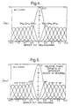
- Figure 5
- illustrates relative phase offsets between the modes of Figure 4;
- Figure 6
- is a schematic view of radiation propagation through a beam splitter of the radiation field analyzer of Figure 1;
- Figure 7
- is a series of illustrations of waveguide modes produced by the Figure 3 mode converter;
- Figure 8
- shows profiles of radiation modes produced by the Figure 3 mode converter;
- Figures 9 and 10
- show theoretical predictions of the performance of the Figure 1 radiation field analyzer;
- Figure 11
- is an experimental measurement of the theoretical result illustrated in Figure 9;
- Figure 12
- is an experimental measurement of the theoretical result illustrated in Figure 10; and
- Figure 13
- is a schematic drawing of an analyzer of the invention incorporated into a laser radar system.
- Referring to Figure 1 there is shown a schematic view of a radiation field analyzer indicated generally by 10. It incorporates a
multimode waveguide structure 12 which has four substantially identical multimode waveguides: aradiation input waveguide 14, amode conversion waveguide 16, a radiation transmit/receivewaveguide 18 and adetector waveguide 20. - The
input waveguide 14 has aninput aperture 22. A CO2 laser source 24 is arranged to direct radiation onto aninput aperture 22.Mode conversion waveguide 16 has anaperture 26. Atunable mode converter 28 is situated at theaperture 26.Mode converter 28 will be described in more detail later. It is arranged to receive fundamental mode radiation fromconversion waveguide 16 and convert it to radiation of any one of a number of desired modes. With the radiation in the desired mode it is then transmitted back to theconversion waveguide 16. In addition to converting the radiation to that of a require mode, a phase modulation or frequency offset of the radiation is also generated in the mode converter. - The transmit/receive
waveguide 18 has anaperture 30. Radiation fromwaveguide 18 is coupled to free space modes outside themultimode waveguide structure 12 via theaperture 30 and alens system 31. Also, radiation in free space modes from external objects is coupled to the transmit/receivewaveguide 18 in waveguide modes via thelens system 31 and theaperture 30. - The
detector waveguide 20 has anaperture 32. Adetector system 34 is arranged to detect radiation emerging fromdetector waveguide 20 viaaperture 32.Detector system 34 is connected to acomputer system 36 for recordal and analysis of the radiation emergent fromdetector waveguide 20. - The
multimode waveguide structure 12 incorporates abeam splitter 38 situated at ends ofwaveguides 14 to 20 opposite toapertures beamsplitter 38 is arranged for substantially equal reflection and transmission of incident radiation (i.e. it is a 50:50 beamsplitter). It is arranged for reflection of radiation frominput waveguide 14 intoconversion waveguide 16 and transmission of radiation frominput waveguide 14 into transmit/receivewaveguide 18. Similarly, radiation fromconversion waveguide 16 is transmitted todetector waveguide 20, and also reflected to inputwaveguide 14. Also, radiation from transmit/receivewaveguide 18 is reflected todetector waveguide 20 and also transmitted to inputwaveguide 14. - The operation of the
radiation field analyzer 10 will now be described in general terms, a more detailed theoretical analysis being given later. Fundamental mode radiation from thelaser source 24 is arranged to couple to theinput waveguide 18 in the EH11 mode, i.e. as fundamental mode radiation. The fundamental mode radiation propagates along theinput waveguide 14 to thebeamsplitter 38. Substantially 50% of the radiation is transmitted through thebeamsplitter 38 to the transmit/receivewaveguide 18. The remaining substantially 50% of the radiation is reflected to theconversion waveguide 16. The radiation in bothwaveguides respective apertures - The radiation which emerges from
aperture 30 couples essentially to the TEM00 free-space radiation mode. It illuminates a scene (not shown) and radiation reflected from the scene is coupled into the transmit/receivewaveguide 18, viaaperture 30. The radiation couples into a number of waveguide modes, of the form EHmn, where m and/or n are greater than or equal to one. - The fundamental mode radiation which emerges from
aperture 26 enters thetunable mode converter 28. Theconverter 28 converts fundamental mode EH11 radiation into higher order waveguide modes EHmn. Theconverter 28 carries out the mode conversion by generating modes in a controlled sequence. Theconverter 28 is controlled by thecomputer 36, via acontrol line 40. Theconverter 28 generates all modes in the range EH11 to EHmn. At any one particular setting, the mode converter only generates a single mode. With m = n = 10 the resolution would be equivalent to a prior art radiation field analyzer having a 10 by 10 array of sub-apertures. - The modes generated by the converter are transmitted to the
conversion waveguide 16 viaaperture 26. A phase modulator in the mode converter imposes a sinusoidal phase modulation on the generated modes. In one implementation the phase modulator takes the form of a fully reflecting mirror mounted on a piezoelectric stack. The stack is driven by a sinusoidally varying voltage which produces a time dependent axial motion of the mirror of the form cos(ωt) where ω is the drive frequency. The amplitude of the drive voltage is arranged so that the limit of the linear motion is λ/2 where λ is the wavelength of a plane wave in the core of the guide. This motion of the mirror imposed a sinusoidally varying phase shift (0 → 360°) on the beam reflected from the mirror. - The phase modulated radiation from the
tunable mode converter 28 propagates along theconversion waveguide 16 towards thebeamsplitter 38. The radiation from the scene or object which is coupled into the transmit/receivewaveguide 18 propagates alongwaveguide 18 towards thebeamsplitter 38. The radiation from theconverter 28 and the radiation from the scene or object are mixed via thebeamsplitter 38 and thence transmitted to thedetector 34. - Because of the orthogonality of the waveguide modes the peak-to-peak amplitude of the power variation measured by the detector will only be non-zero when the EHmn mode from the scene or object equates to the EHmn mode generated by the tunable mode converter. For example, when the
mode converter 28 generates the EH31 mode, there will only be a finite power variation in the transmit/receivewaveguide 18 when the radiation from the scene also results in excitation of the mode EH31. The resulting sinusoidal variation in the power is recorded by thecomputer 36 and used to deduce the modulus and phase of the EH31 component in the field from the scene. Consequently, from knowledge of the mode settings and the relative amplitudes and phases of the modes generated by thetunable mode converter 28 and of the sinusoidal power measurements made by thedetector 34, the complex amplitudes of all the EHmn radiation modes present in the radiation received from the scene can be determined. - This enables the radiation field from a scene to be characterized according to the EHmn modes excited in the transmit/receive waveguide. The higher the order of modes used in the analysis, the greater the resolution by which the scene radiation field can be characterized. Lower order modes may provide information on the bulk characteristics of the scene; for instance the presence of EH21 mode, with two intensity peaks, indicates the presence of two main vertical components in the scene. Conversely, higher order modes such as the mode EH10,10 provide information about smaller scale detail of the scene. Consequently, scene radiation fields can be characterized in terms of the EHmn modes which it excites. Scene radiation fields may be calibrated; i.e. a known object field may be characterized in terms of the EHmn modes which it produces, and the
analyzer 10 may then be arranged to register when the EHmn modes corresponding to that object are received by thedetector 34. Theanalyzer 10 may then be used as the basis of a surveillance system in which objects to be detected by theanalyzer 10 are initially calibrated in terms of the EHmn modes which they excite. - Figure 2 is a perspective view of the
multimode waveguide structure 12 of Figure 1. Themultimode waveguide structure 12 is fabricated from alumina. It is composed of three layers: asubstrate layer 210 forming the lower walls of the hollow waveguides, awaveguide layer 212 comprising an arrangement oftiles 213 forming the vertical walls of the hollow waveguides, and atop layer 214 indicated by dotted lines and forming the upper walls of the hollow waveguides. - The
waveguide layer 212 defines the shape of theinput waveguide 14, themode conversion waveguide 16, the radiation transmit/receivewaveguide 18 and thedetector waveguide 20 shown in Figure 1. Each of the resultinghollow waveguides 14 to 20 is of constant square cross-section ofside 2a where a is equal to one millimetre. - The dispositions of the
waveguides 14 to 20 will now be described with reference toaxes 216. Themode conversion waveguide 16 anddetector waveguide 20 have respective centrallongitudinal axes Axis 220 is offset fromaxis 218 by 0.93 mm in the positive y-direction. Similarly,input waveguide 14 and transmit/receivewaveguide 18 have centrallongitudinal axes Axis 222 is offset from axis 224 a by 0.93 mm in the positive x-direction. - The
waveguide layer 212 also has twoslots waveguides waveguides beamsplitter 38 is situated inslots common intersection 232 of thewaveguides 14 to 20. The beamsplitter is fabricated from zinc selenide and has a thickness of 1.9 mm. A multidielectric coating is evaporated onto its surface allowing 50% of the incident light to be transmitted and 50% reflected. - The
waveguides 14 to 20 haverespective apertures waveguide layer 212. Thelaser source 24 is centrally located onlongitudinal axis 222.Tunable mode converter 28 is centrally located onaxis 218, 1.0 millimetre distant fromaperture 26 ofconversion waveguide 16. Thedetector 34 is a cooled 4.0 mm square chip of cadmium mercury telluride (CMT) which is located centrally onaxis 220; it is positioned so as to capture all of the radiation emitted from theaperture 32. - Figure 3 shows a perspective view of the
tunable mode converter 28 of Figure 1. It incorporates amultimode waveguide structure 310 comprising four hollow waveguides. Thestructure 310 comprises threelayers Layer 312 consists of asubstrate plate 313 which forms the lower walls of the hollow waveguides,layer 314 comprises an arrangement oftiles 315 which form the vertical walls of the hollow waveguides andlayer 316, indicated by dashed lines, is a top plate 317 which forms the upper walls of the hollow waveguides. - The arrangement of
tiles 315 forms fourmultimode waveguides Waveguide 318 is an input waveguide;waveguide 320 is a first mode conversion waveguide;waveguide 322 is a second mode conversion waveguide; andwaveguide 324 is a mode checking waveguide. Each waveguide is of square cross-section of side 2.0 mm. Eachwaveguide 318 to 324 has arespective aperture layer 314. - The
waveguides 318 to 324 have corresponding centrallongitudinal axes Axis 338 is offset fromaxis 334 by 0.93 mm in the positive y-direction, as indicated byaxes 342. Similarly,axis 336 is offset fromaxis 340 by 0.93 mm in the positive x-direction. In operation,axis 334 is parallel and coaxial with theaxis 218 of Figure 2. - The
layer 314 has twoslots Slot 334 is situated at the intersection ofwaveguides waveguides slots zinc selenide beamsplitter 348, of thickness 1.96 mm. - The first and second
mode conversion waveguides axis apertures mirrors mirrors Mirror 350 is rotatable aboutcentral axes Mirror 352 is rotatable aboutcentral axes mirrors waveguide apertures computer 36 of Figure 1. - The
mode converter 28 is located adjacent to themultimode waveguide structure 12 such that light fromaperture 26 couples intoaperture 326 ofinput waveguide 318 of theconverter 28. - The operation of the
mode converter 28 will now be described. Fundamental moderadiation entering aperture 326 propagates alonginput waveguide 318 tobeamsplitter 348. Asbeamsplitter 348 is a 50:50 beamsplitter, essentially half the incident radiation is transmitted through it to the firstmode conversion waveguide 320. The substantial part of the remainder is reflected into the secondmode conversion waveguide 322. The radiation propagates alongwaveguides apertures mirrors apertures - The coupling of the reflected radiation from
mirrors waveguides mirrors waveguide 320 after reflection frommirror 350. The same graph applies for radiation coupled frommirror 352 towaveguide 322. It can be seen that the moduli of the waveguide modes coupled into the waveguides varies with tilt angle of the respective mirror. Positive tilts relate to clockwise rotations of themirrors - From the graph it can be seen that at zero tilt then only EH11 radiation mode is coupled to the respective waveguides. However, at increasing positive tilts the modulus of the EH11 mode decreases until it becomes substantially zero at 11.0 milliradians tilt. Conversely, the modulus of, the EH21 mode increases rapidly at positive tilts, to a maximum of about 2.5 milliradians tilt. The maximum amplitude of the modulus of the mode EH21 does not, however, reach a value equivalent to that of the EH11 mode; rather it is restricted to about two-thirds of that value.
- At higher positive tilts the other higher order modes: EH31, EH41, EH51 etc., also begin to be coupled to the respective waveguides. These modes have maximum amplitudes at about 4.0, 5.5 and 7.0 milliradians of mirror tilt respectively. Their maxima are substantially the same as that of EH21 mode. For negative mirror tilts the moduli of all modes are the same as for positive tilts, however their phases are different. The mirror tilt required to maximize the amplitude of any given mode, except EH11 (for which the maxima is achieved with zero tilt), can be predicted to a good approximation by the formula: = mλc/8a, where, '' is the tilt in radians, 'm' is the mode number of the EHm1 th mode, 'λc' is the wavelength of a plane wave in the core of the guide (in the case of hollow waveguides, the wavelength of a plane wave in free space), and a is the half width of the waveguide. For example, if m = 3, λ = 10.6 µm, and a = 1.0 mm, then = 0.003975 radians, i.e. approximately 4 milliradians in good agreement with the numerical predictions of Figure 4.
- Whilst Figure 4 highlights how the moduli of the excited modes varies as a function of mirror tilt Figure 5 illustrates how, in addition, the phase offsets between the modes are also a function of mirror tilt. It can be seen that for positive mirror tilts the antisymmetric modes EH21 and EH41 are offset by 90° (or π/2) from the symmetric modes EH11, EH31 and EH51. Conversely, for negative mirror tilts the antisymmetric modes are offset by 270° (3π/2).
- From Figure 4 and 5 it can be seen that for any particular mirror tilt angle a multiplicity of modes are coupled to the respective waveguide. For example, for a positive tilt of 4 milliradians there are contributions from modes EH11, EH21, EH31, EH41 and EH51. However, the magnitudes of the moduli of the modes are different. The modulus of the fundamental mode is about 0.05, as is that of EH51, the moduli of modes EH21 and EH41 is approximately 0.25, whilst the modulus of EH41 is maximized at a value of 0.4.
- For the analysis of radiation from a scene by the technique outlined, it is desirable that the
mode converter 28 should generate substantially single EHmn modes at any one time. If it generates multiple modes then these may beat with multiple modes from the scene radiation field to be analyzed, causing multiple beat signals. More sophisticated signal processing techniques would then be required in order to determine which modes were present in the radiation detected bydetector 34. If single modes could be generated by the mode converter the analysis could be much simpler. - With the aim of generating essentially pure modes, the symmetric and antisymmetric modes may be separated so that approximately only one mode is produced from the
mode converter 28 at any one time for any given mirror tilt. The modes are separated by virtue of the coherent mixing process at thebeamsplitter 348. - Figure 6 shows a schematic view of the propagation of radiation through the beamsplitter. The
beamsplitter 348 has twofaces face 602 has a multidielectric coating providing 50% transmission and 50% reflection. Consequently radiation propagating towards thebeamsplitter 348 is transmitted through and reflected from theface 602 towaveguides refractive index beamsplitter 348 and low refractive index air adjacent to it. For radiation approaching this interface frommirror 352 the radiation is travelling in a low refractive index medium and is reflected at the air interface with the high refractive index medium of thebeamsplitter 348. The radiation undergoing this reflection does not undergo a phase change. Conversely, the radiation approaching the interface from themirror 350 is travelling in the high index medium of the beam splitter and is reflected from the interface with the lower refractive index medium - i.e. the air surrounding thebeamsplitter 348. The radiation undergoing this reflection undergoes a π radian, or one hundred and eighty degree phase shift. - Following the coupling of radiation into
waveguides mirrors mirrors waveguides output waveguide 318 the phase difference between radiation frommirrors waveguides waveguide 318 frommirror 350, and mn352 is the phase of the same mode injected intowaveguide 318 frommirror 352. - In order to achieve this situation for any given mode the
mirror 350 is arranged for lateral movement in the x-direction (axial movement along the guide axis) over a distance x. This movement produces a phase change c in mn350, given by:laser source 24 is a CO2 laser, the wavelength of the free space radiation is 10.6 µm. To obtain a phase change c would require a movement x = λmnc/4π. In practice, in order that like modes are in phase, c would be adjusted so that (mn352 - mn350) would be an integral multiple of 2π radians. - From Figure 5, it can be seen that for positive tilts of
mirror 350 about the z-axis (see Figure 3) the antisymmetric modes EH21, EH41, EH61 etc., are offset by 90° from the symmetric modes, whilst for negative tilts of themirror 350 about the z-axis the antisymmetric modes EH21, EH41, EH61 etc., are offset by 270° from the symmetric modes. Considering the situation wheremirror 350 has a positive tilt, andmirror 352 has a positive tilt (which following reflection from thebeamsplitter 348 equates to an effective negative tilt inoutput guide 318 as far as the relative phases of the modes are concerned), if by the application of an appropriate phase shift, applied via the piezo-electrically controlled displacement ofmirror 350 it is arranged that the symmetric modes transmitted by thebeamsplitter 348, frommirror 350 intooutput guide 318, are in phase with the symmetric modes reflected by thebeamsplitter 348, frommirror 352 intooutput guide 318; then these symmetric modes will constructively interfere at point 604, and produced a beam of symmetric modes which will be coupled intowaveguide 318. Conversely with the same mirror tilts the transmitted and reflected antisymmetric modes frommirrors waveguide 318. Simultaneously, these antisymmetric modes will be in phase in the outgoing field ofwaveguide 324 and will interfere constructively, whilst the symmetric modes in outgoing field ofwaveguide 324 will be out of phase and will interfere destructively. - Conversely, where the
mirror 350 is displaced so as to achieve destructive interference between the symmetric modes in the outgoing field inwaveguide 318 the antisymmetric modes will be in phase and will interfere constructively. Simultaneously inwaveguide 324 the outgoing symmetric modes will interfere constructively and the antisymmetric modes will be absent. - In the above situation the mode set which is coupled to
waveguide 324 may be used as a check on the modes which are produced in the output field ofwaveguide 318 i.e. the output from themode converter 28. For example, if antisymmetric modes are to be output viawaveguide 318 then waveguide 324 must contain symmetric modes, and vice versa. Thewaveguide 324 may have a detector array (not shown) opposite itsoutput aperture 322 for the purpose of analysing the modes. - The previous argument demonstrates how the output radiation from the
mode converter 28 can be selected to be either a symmetric or an antisymmetric mode and how the purity of a given mode can be maximized by choosing the tilt magnitudes on themirrors - From the graph of Figure 4 it can be seen that for zero mirror tilt then the only mode generated in the fundamental mode EH11. At 4.0 milliradians of mirror tilt the EH31 is the dominant mode produced, but there are also small contributions from EH51 and EH11 modes. Antisymmetric modes are being ignored here, as these can be eliminated as previously described. By measuring the output of the analyzer with the
mode converter 28 set with zero tilt ofmirrors - The amplitude of the EH31 mode can be determined by measuring the output from the analyzer with the mirrors in the mode converter set to tilts of +2.5 milliradians. From Figure 4 the contribution of the EH31 and EH11 modes are substantially the same and all other symmetric modes have very low magnitudes. The amplitude of the EH11 mode at 2.5 milliradians of mirror tilt can be determined from the previous measurement at zero tilt. From the graph of Figure 4 the amplitude of the EH11 mode varies with mirror tilt in a known manner, and the amplitude at any tilt can then be found from the amplitude at zero tilt. As the EH11 amplitude at 2.5 milliradians is known the contribution to the EH31 mode signal can be deduced. Similarly, at 5.5 milliradians of mirror tilt the amplitude of the EH51 mode can be determined, from knowledge of the previously determined EH11 and EH31 modes and of the output of the analyzer with the mirrors in the
mode converter 28 set to this mirror tilt. - Similarly, from Figure 4, when the antisymmetric modes are selected by appropriate setting of the PZT the amplitude of the EH21 mode can be found by measuring the output from the analyzer when the mirrors in the mode converter are set at +1.5 milliradians of tilt. Here, the mode converter output is mostly due to the EH21 mode, with EH41 having only a small contribution. At +4.0 milliradians the contributions from EH21 and EH41 are the same with the amplitudes of all other antisymmetric modes being extremely small. By measuring the output from the analyzer in this situation and compensating for the contribution of the EH21 mode the amplitude (i.e. modulus) of the EH41 mode can be deduced.
- From the foregoing it can be seen that the scene radiation field received by the analyzer can be characterized in terms of the individual modes present, by arranging for only symmetric or antisymmetric modes to be produced and by a knowledge of the modes generated at various tilt angles or mirrors 350 and 352.
- The foregoing has been concerned with the generation of EHm1 modes. This is achieved by tilting
mirrors mirrors - Higher order modes with both m and n greater than 1 can also be generated by the
mode converter 28. This can be achieved simultaneously titling themirrors mirrors mirrors - Figures 7a and 7b are illustrations of the mode outputs produced by the
mode converter 28 at differing settings. Figure 7a shows the radiation intensity patterns output fromwaveguide 316 when themode converter 28 was set to produce modes EH11 up to EH10,1. For example, the EH41 intensity pattern has a horizontal row of four intensity peaks. Figure 7b shows the radiation patterns output from thewaveguide 316 when themode converter 28 was set to produce modes EH11 up to EH1,10. As an example, the EH17 pattern has a vertical column of seven intensity peaks. The fundamental mode EH11 consists of a single central intensity peak. In general, intermediate mode patterns have various combinations of columns and rows of intensity peaks. The EHmn th mode has mxn intensity peaks. - Figure 8 shows quasi three dimensional profiles of four of the modes produced by the
mode converter 28, the modes being EH11, EH21, EH31, and EH41. It can be seen that these modes have respectively, one, two, three and four, intensity peaks. - The radiation from the
mode converter 28 couples into theconversion waveguide 16 viaaperture 26. The multimode radiation from the scene couples into the transmit/receivewaveguide 18 viaaperture 30. The radiation in therespective conversion waveguide 16 and transmit/receivewaveguide 18 propagates towards the 50:50beamsplitter 38. - The radiation from the scene is composed of a linear combination of EHpq modes with respective complex amplitude Apqexp (ipq). The EHpq modes are produced by an input optical field, Einput, coupling to the
waveguide 18 ataperture 26. Consequently, Einput can be represented by the Epq modes as
- Essentially, the
waveguide 18 carries out a Fourier analysis of the optical field Einput at itsentrance aperture 26. The complex amplitudes are then the coefficients of the Fourier series and the modes excited in thewaveguide 18 are a modal representation of the field from the scene. - The radiation modes in
waveguides beamsplitter 38. By moving themirrors - The coherent beating of an EHrs mode from the converter and the mode spectrum from the scene results in a beat field which is propagated along the
detector waveguide 20. It emerges fromaperture 32 and is detected atdetector 34. Under these conditions, the time varying 2D intensity profile produced on thedetector 34 is given by:
- Here Apq and Ars are the moduli of the complex amplitudes of the modes in the scene field and those produced by the mode generator, respectively, and ρ is the difference of their arguments, (ρpq - ρrs), i.e. their phase difference. By integrating over the waveguide cross-section the time variable component of the power falling onto a detector which captures all the radiation emanating from the guide, is given as:and the peak-to-peak value of Pb as:


- Because of the orthogonal nature of the waveguide modes the integral term and hence the peak-to-peak amplitude of Pb will only be non-zero when the modes are of the same order, i.e. p = r and q = s, simultaneously. Under this condition the value of the peak-to-peak amplitude of Pb coupled with a knowledge of the magnitude of Ars, allows direct evaluation of, Apq, the modulus of the complex amplitude of the mode EHpq. Furthermore, by making comparative measurements of the relative phase offsets between the sinusoidal variation of Pb and the piezo-electric modulator drive signal, for different mode settings of the mode tunable local oscillator, the relative phase differences between the modes can also be established. In this manner the complex amplitude of each mode in the input field can be measured hence the complete form of the field can be deduced.
- In practice the accurate measurement of the relative phases of the modes in the input field is based on two important assumptions.
- (i) That the waveguide optical path length between the entrance aperture of the waveguide (into which the field which is to be analyzed is imaged) and the detector is equal to the waveguide optical path length between the output from the mode converter and the detector. If this were not the case, corrections would have to be made to the measurements based on the mode dispersion equation.
- (ii) That the individual modes produced at the output plane of the mode converter all have the same relative phase. If this were not the case the relative phase offsets would have to be established in an initial set-up procedure. This could be based on the injection of a known input field, e.g. the EH11 field returned from a tilted mirror. The values of the phase offsets deduced in this manner could either be used to correct the measured data in the computational phase of the field analysis process. Alternatively the phase offset data could be used to establish zero phase offsets between the generated modes by applying suitable d.c. offset voltage levels to the phase modulator in the mode converter for each mode generated. This process is analogous to the "phase up" procedure which has to be undertaken in phased array receivers in order to ensure that the phases of the local oscillator signals applied to the mixing points behind each subaperture are the same.
-
- The
analyzer 10 may be calibrated before use by locating a target mirror (not shown) at theaperture 30 of transmit/receivewaveguide 18. The mirror can be tilted to generate the modes analogous to those of Figure 4. Consequently the relative phases of the modes propagating inwaveguide 18 can be deduced from the output ofdetector 34, by beating the EHmn modes from theconverter 28 with the modes generated by the target mirror. The amplitude and phase of the modes generated by theconverter 28 are known, and the amplitude of modes generated by the target mirror are also known. This enables the relative mode phases to be deduced. - A calibration procedure which would take account of phase offsets between the modes generated by the mode converter is now considered in more detail. With reference to Figure 1 consider the situation where a target mirror placed at the
aperture 30 is tilted by -4.0 milliradians about the z-axis. From Figure 4 it is known that this results in excitation of modes EH11, EH21, EH31, EH41, and EH51. The mode converter is tuned to EH11 and the phase difference, χ1, between a sample of the drive signal applied to the phase modulator in the mode converter and the output from the detector is measured. In practice this could be done with an oscilloscope. The mode converter is then tuned to provide the mode EH2 and the phase difference measurement is repeated. The result this time is a value χ2. From Figure 5 it is known that χ2 - χ1 should equal 270°, the correction to χ2 is defined as χ2c, and evaluate it such that χ2 + χ2c - χ1 = 270°. The value of χ2c is recorded. In an analogous manner the phase corrections for the other modes excited by this value of tilt magnitude are evaluated. The target mirror is now tilted by -9.0 milliradians, this results in excitation of modes EH51, EH61, EH71, EH81 and EH91. This value of tilt was chosen to include EH51 which occurred in the first data set. Measurements of the relative phase offsets with respect to EH11 from the initial set of measurements which included EH11 and EH51. The strategy of overlapping the sets of modes for which measurements are made is important because in moving from one value of mirror tilt to another, unless the axis of rotation runs exactly through the waveguide axis, which is unlikely in practice, an axial shift of the mirror surface is also effected which introduces and additional unknown phase shift. - Tilts of the target mirror about the orthogonal x-axis and compound tilts about both the horizontal and vertical axes allow access to a large mode spectrum. In this context, as described earlier, the value of mirror tilt required to excite a given set of modes is to a good approximation given by, = nλ/8a, where, n is the number related to the mode at the centre of the set and, a, is the half width of the waveguide. For example if it is desirable for EH31 to be the centre of the set then n = 3, and with λ = 10.6 µm and a = 1.0 mm, this gives = 4 milliradians as used earlier. If it is desirable for mode EH33 to be at the centre of the set excited, the mirror would be tilted by 4.0 milliradians about both the x and z axes. With a computer controlled mirror mount and suitable interface electronics the whole set-up process could be automated.
- If it were desirable to analyze the tilted input field at any value of tilt magnitude illustrated in Figure 4 then a mode tunable local oscillator would be needed which would at least produce modes EH11 to EH51. It would then be necessary to make moduli and phase measurements for each of the five modes in turn. Because of the unique nature of the input field it is interesting to note that any point in the range the maximum number of modes simultaneously excited is, five. Images of real objects are likely to result in much more complex mode spectra in terms of both the numbers and orders of the modes excited. The resolution with which such images could be analyzed will depend on a number of factors, these include:
- (i) the highest order mode accessible with the mode tunable local oscillator,
- (ii) the purity of the modes it produces, and
- (iii) the accuracy with which the modal amplitude and phase measurements can be made. With temporally varying fields another important factor will be the time taken for the measurement to be made. This will depend on the number of modes the analysis is made with and the time taken for each measurement. The latter will itself depend on how quickly the peak-to-peak value of Pb can be evaluated and this in turn will be a function of the phase modulation frequency. Signal to noise issues are also likely to effect overall measurement resolution and time.
-
- Because the approach to field analysis described is reliant on performing sequential measurements on each of the modes that the local oscillator can be tuned through, although potentially very fast, it is inherently slower than a phased array which in principle is real time. However, the mode analysis approach has significant technological advantages over the phased array in that it only requires a single aperture and a single detector to form a very sophisticated coherent field measuring system. As such it might well be possible to upgrade existing single aperture, single detector systems, with the addition of a mode tunable local oscillator. Additionally, the fact that the complex mode amplitude outputs from the system provide a direct Fourier transform of the object field, could have significant advantages as far as image processing, pattern recognition and data storage are concerned. In the context of increasing the speed of measurements it is possible to conceive systems where several local oscillators running on different modes are used to make simultaneous measurements of the different spatial components of a field. In relation to phased array systems the modal analysis approach might also be used to provide improved resolution behind each sub-aperture. Hybrid systems based on a combination of phased array and modal analysis techniques might lead to new approaches to coherent receiver design.
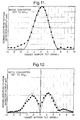
- Figures 9 and 10 show predictions of the way in which the peak-to-peak amplitude of the beat signal received by the
detector 34 would vary if the scene was itself a mirror placed at the exit ofwaveguide 18 and was tilted from -10 milliradians to +10 milliradians. Figure 9 relates to the case where the mode converter was set to produce the fundamental EH11 mode, whilst in Figure 10 the mode converter is set to generate the mode EH12. It can be seen that signal maxima are recorded at the target mirror tilt angles which maximize the coupling to the mode which the mode converter is tuned to. Figures 11 and 12 illustrate comparisons of the theoretical predictions illustrated in Figures 9 and 10 with experimentally generated results for the case where the mode converter is tuned to EH11 and EH21 respectively. - Different designs of mode converter based on multimode waveguides are possible. Essentially, the mode converter design described herein is a multimode waveguide version of the Michelson interferometer. The interferometer serves the purpose of allowing the fundamental mode input field to be split into two components which are then given appropriate tilt magnitudes of opposite senses, before being recombined. A multimode waveguide version of the Mach-Zehnder interferometer could provide a similar function. In the Michelson and Mach-Zehnder versions of the mode converter, improved mode purity can be achieved by increasing the waist size of the TEM00 input beam. The generated modes would be perfect if the input field was a plane wave. However, in the case of TEM00 input fields where the input beam waist, w, is greater than 0.7a, the waveguide optical path length between the input plane and the fully reflecting tiltable mirrors must be an integer multiple of the length of multimode waveguide required to provide input field regeneration. This length of multimode waveguide is given as, L = (2a)2/λ, for a hollow dielectric waveguide.
- The most general implementation of the mode generation process is achieved by launching two plane wave beams of opposite tilts and with an appropriate phase offset between them into a multimode waveguide. The waveguide could be of zero length, i.e. an aperture. The tilted beams may be produced by acousto-optic or electro-optic modulators. In these embodiments, the processes of scene illumination, mode generation and field analysis could be simplified if they were to be performed independently. In such embodiments, the output from a laser source could be split into major and minor components. The major component would be used to illuminate the scene whilst the minor component would act as the input to a mode generator. The output from the mode generator would then be mixed with the field returned from the scene in a separate multimode interferometer such that the mode analysis could be performed.
- Other ways of generating the required spectrum of mode for the mode tunable local oscillator are also possible. For example the
tunable mode converter 28 may be replaced by a waveguide laser with a square cross section providing controllable multimode output. Higher order modes can be generated by varying the way in which the gain medium is pumped, by tilting the resonator mirrors, by varying the cavity length and by placing a moveable grid of wires over the resonator mirrors. In this configuration aseparate laser source 24 operating on the fundamental quasi-Gaussian mode would be used to illuminate the scene. If thelaser source 24 and the mode tunable laser are stabilized in order to prevent relative drift in their frequencies, they could be frequency offset with respect to one another in order to generate a know high frequency beat signal. The fact that the different laser modes of the mode tunable laser will have different oscillation frequencies will also mean that the mode that the mode tunable laser is running on can be identified from the beat frequency. This could be used as a discriminant in order to lock the mode tunable laser to a given mode. For example, if the mode output of the laser changed as a function of the voltage applied to a piezoelectric cavity length controller, an electronic feedback circuit could be designed to keep the cavity length at a value that produced a given beat frequency and hence a given transverse mode. - The concept has been described in the context of mixing the modes generated by the mode generator/converter together with the field to be analyzed in a multimode waveguide structure and then detecting the resultant field on a detector placed at the exit of the multimode waveguide. The mixing process need not be undertaken in a multimode waveguide. Mixing could be arranged to occur on a multidielectric etalon mounted in free space with the resultant field detected on the face of a detector mounted in free space. In order for this embodiment to operate correctly the modes generated in the mode converter/generator would need to be accurately imaged onto the detector. In order to understand this embodiment it is useful to think of the detector as a multimode waveguide of zero length.
- The embodiments described so far have only considered field analysis in the context of the orthogonal modes of square sectioned waveguides. Analysis could be undertaken with the more general class of modes of rectangular sectioned waveguides or the Bessel modes of circular cross sectioned waveguides. Any waveguide which supports a power orthogonal set of modes could be used as the basis of an analyzer.
- The embodiments described so far have only considered field analysis in the context of power orthogonal waveguide modes. Analysis can be undertaken in terms of any set of power orthogonal optical field functions which can be generated. These could be the Hermite-Gaussian modes defined in relation to a rectangular coordinate free space system, or the Laguerre-Gaussian modes of a cylindrical coordinate free space system. In these implementations the lateral extent of the modes varies with their order. The higher the order of the mode the larger its width. In this case the detector would need to be large enough to capture the highest order mode that was required for the analysis. This differs from the waveguide mode implementations were the lateral extent of all modes is defined by the waveguide cross section.
- The embodiments described so far have only considered field analysis where the analysis process is undertaken in a multimode waveguide or free space version of the widely used Michelson interferometer. Other forms of interferometer can be used to perform the field analysis process, including both multimode waveguide and free space versions of the Mach-Zehnder interferometer. The use of Mach-Zehnder type interferometers solely based on multimode waveguides is also possible. Here, a suitably design multimode waveguide takes the place of the etalon in the embodiment described herein. The resulting all-waveguide interferometer has two multimode input waveguides to carry: (i) the field to be analyzed, and, (ii) the output from the mode converter/generator. These input guides feed into another wider multimode waveguide section which provides the mixing function. The resultant fields of the mixing process are carried out in two multimode output guides. A detector placed at the exit of one would be used to make the beat measurements. The all-waveguide form of interferometer could also be used as the basis of a mode generator/converter. In integrated optic implementations of the all-waveguide mode generator/converter electro-optic phase modulators or SAW devices could be used to generate the linear phase shifts produced by the tilted mirrors in the embodiment described in detail herein. Such modulators could also be used to provide a frequency offset between the output from the mode converter and the scene field to be analyzed.
- The
analyzer 10 may be incorporated in an array of like analyzers. The array may be arranged to receive reflected radiation from a scene. Each individual analyzer such as 10 may be arranged to generate a set of modes in its mode converter such as 28. For example, theanalyzer 10 may be arranged to detect modes EH11 to EH10, whereas a second analyzer may be arranged to detect modes EH21 to EH2,10 etc. This enables more rapid analysis of modes reflected from a scene. Such an application may be particularly useful for surveillance work, where the nature of a scene must be analyzed rapidly. - An array of analyzers in which each was arranged to detect a full spectrum of modes, could also act as an alternative form of phased array receiver. In this arrangement, the field resolution at any sub-aperture, and hence the resolution of the complete array, would be significantly better than that achievable with a conventional phased receiver array based on the sole use of fundamental mode local oscillators at each sub-aperture.
- In the multimode waveguide embodiments of the concept described so far, the multimode waveguides have been hollow in nature and have cross sections of millimetres. In such waveguides there is an air core surrounded by a dielectric cladding. For 10.6 µm radiation from a CO2 laser source, polycrystalline alumina is a good cladding material in terms of creating low loss waveguides because of its appropriate complex refractive index properties (i.e. n<1 at 10.6 µm). When using such dielectric materials, the hollow multimode waveguide structure may be fabricated from a series of plates of the dielectric material. Alternatively, it may be formed from a block of the dielectric material, with the waveguides being etched or machined into the block.
- Hollow waveguide integrated optic structures have been constructed from solid pieces of polycrystalline alumina obtained from Kyocera Ltd of Japan using a computer numerical control (CNC) machining process to form both hollow waveguides and the slots to take optical components, such as the
beam splitter 38 and thebeamsplitter 348. The CNC machining was carried out in a two stage process. In a first stage, using a coarse milling process, the bulk of the excess alumina was removed. In a second stage, a jig grinder was used to obtain the final finish. Using this two stage process, component alignment slots could be produced with angular alignment tolerances of ± 0.5 mrad, and hollow waveguides could be constructed which maintained fundamental mode fidelity to a degree in excess of 98% (defined in terms of guide to guide coupling) for 2.0 mm wide waveguides. - The multimode waveguides need not be hollow waveguides, they can be solid core waveguides with a solid cladding. In such waveguides the refractive index ratios between the core and cladding are arranged to as to allow the waveguide to support many modes. GaAs/AlGaAs waveguides can be designed to be multimode. The waveguide structures are etched into a suitably designed epitaxial layer using ion beam assisted etching techniques. GaAs/AlGaAs waveguides of a few micrometers cross section can be designed to support many modes. In this context, it is interesting to note that, as the field resolution achieved with the analyzer concept described herein is dependent on the highest order mode that a measurement can be undertaken for, and not the lateral extent of the detector used to make the measurement; systems based on small dimension waveguides which support a good spectrum of higher order modes could provide very high resolution field analysis capabilities. Such analyzers could be useful for coherent microscopy, and could also be very useful for making field measurements at points in the electromagnetic spectrum where small dimension detector arrays are not available.
- In the embodiments described so far the radiation has been 10.6 µm radiation from a CO2 laser source. In principle with the right optical/waveguide technologies and laser/maser sources, the underlying concepts are applicable across the electromagnetic spectrum.
- Implementation of the underlying concepts need not be solely based on the use of laser sources. Narrow linewidth quasi-coherent light sources can be used as an alternative to a laser. In this context light from distant astronomical objects can also be analyzed in a suitable implementation of the analyzer. In such an implementation there would be two receiver apertures. The received light from one would be modally filtered in order to provide a fundamental mode input for the mode converter. The output from the mode converter would be mixed with the field received from the other aperture. As the fundamental mode content of the input to the mode converter would vary due to variations in the fundamental mode component of the received field, this would have to be monitored and used to apply a suitable correction to mode amplitude measurements.
- In a further embodiment, an analyzer can be arranged to act as a transmitter. By suitable control of the relative mode amplitudes and phases at the outputs of the analyzer, a transmitted beam can be produced from a suitable sum of independently generated EHmn modes.
- Referring now to Figure 13, there is shown a laser radar system indicated generally by 700 incorporating a radiation field analyzer of the invention. Polarization directions of radiation beams within the
system 700 are indicated byarrows 702 andcircles 704, which correspond respectively to linear polarization in the plane of the drawing and perpendicular to it. Thesystem 700 incorporates a CO2 laser source 706 with anoutput radiation beam 708 of approximately 5 watts power, having a 10.6 µm free-space wavelength and having a beam diameter of 2 mm. Abeam splitter 710, fabricated from a plate of zinc selenide onto which a multidielectric coating has been vacuum-evaporated, lies in the path of thebeam 708 and defines transmitted and reflectedbeams beam 712 lies azinc selenide plate 716 inclined to the path at the Brewster angle, a quarter-wave plate 718, and a telescope arrangement of concave andconvex lenses - In the path of the reflected
beam 714 lie a half-wave plate 724, an acousto-optic modulator 726 and atunable mode converter 728 which is similar to themode converter 28 described earlier. Themodulator 726 provides phase modulation of incident light at a phase modulation frequency of 60 MHz with modulation limits of +π and -π radians. Themode converter 728 has a modecontrollable output beam 730 directed to acombiner plate 732 and a liquid-nitrogen cooled cadmiummercury telluride detector 734 having a bandwidth of 500 MHz. Thedetector 734 is connected to asignal processing unit 736 incorporating a computer (not shown) which is connected in turn to amode control input 738 of themode converter 728. - The
radar system 700 operates as follows. Thelaser beam 708 is linearly polarised in the plane of the drawing, and is partly transmitted and partly reflected by thebeam splitter 710. The transmittedbeam 712 is incident on thezinc selenide plate 716 through which it is transmitted efficiently by virtue of its polarization direction to form an outward beam in aregion 742 located between theplate 716 and the quarter-wave plate 718. The outward beam in theregion 742 is subsequently transmitted through the quarter-wave plate 718 which changes the linearly-polarised outward beam into a circularly-polarised outward beam in aregion 744 located between the quarter-wave plate 718 and theconcave lens 720. The circularly-polarised outward beam in theregion 744 is then magnified by the concave andconvex lenses beam 740. Thebeam 740 illuminates a remote scene (not shown) at a distance which may be of the order of 5 km. When thebeam 740 is incident at a remote scene 5 km distant, its diameter is approximately 1 metre as a result of beam divergence. Incident coherent radiation is reflected or scattered from the remote scene and part of the reflected or scattered radiation re-enters theradar system 700 through thelenses region 744; the intensity of the coherent radiation which re-enters theradar system 700 is approximately a few femtowatts. The return beam in theregion 744 is then transmitted through the quarter-wave plate 718 which changes the circularly-polarised return beam in theregion 744 to a linearly-polarised return beam in theregion 742. The linearly-polarised return beam in theregion 742 is subsequently incident on thezinc selenide plate 716 which reflects efficiently components of the return beam in theregion 742 to form a reflectedbeam 746 which is orthogonally polarised relative to the outward beam in theregion 742. The reflectedbeam 746 is incident on thecombiner plate 732 from whence it is reflected into thedetector 734 along apath 748. - The reflected
beam 714 is transmitted through the half-wave plate 724, providing a polarization rotation of π/2 radians, after which it is transmitted through the acousto-optic modulator 726 into themode converter 728. Themode converter 728 converts input radiation contained in thebeam 714 into a series of different modes which are individually selected by a control signal applied to themode control input 738. These modes are output to form thebeam 730. Thebeam 730 is transmitted through thecombiner plate 732 to be incident on thedetector 734 where it creates interference with thebeam 746 reflected from thecombiner plate 732; radiation incident on thedetector 734 creates an output signal which is conveyed to thesignal processing unit 736. The effect of the acousto-optic modulator 726 applying a 60 MHz phase modulation to the reflectedbeam 714 is to create 60 MHz periodic-variations in the output signal at thedetector 734; the difference between maximum and minimum intensities in the output signal at thedetector 734 provides an indication of the magnitude of laser radiation reflected from the remote scene for a particular selected radiation mode generated by thetuneable mode converter 728 and for a given output power of thelaser 706. The output signal generated at thedetector 734 is conveyed to theprocessing unit 736 which analyzes the signal to provide output data corresponding to the difference between maximum and minimum radiation intensities for each of the modes which are selected by means of a control signal supplied to themode control input 738 of themode converter 728. - An advantage of this form of signal analysis as described above is that the average level of radiation incident upon the
detector 734 is disregarded, although any random fluctuations in that average level, arising for example from any random fluctuations in the radiation power contained in thebeam 708 emitted from thelaser 706, will have the effect of degrading the signal-to-noise ratio of the output data described above. Thus, it is beneficial to try to minimise the coupling of radiation to thebeam 746 which does not arise from reflection of coherent radiation from the remote scene; however, it is desirable to ensure that the power of thebeam 730 emitted from themode converter 728 is at least greater than the maximum power expected in the received radiation which is reflected from the remote scene and which re-enters thelaser radar system 700 in order to ensure that the difference between maxima and minima in the signal from thedetector 734 is proportional to the amount of reflected radiation from the remote scene and not limited by the available power in thebeam 730 emitted from thetuneable mode converter 728. The power in thebeam 730 may be in the order of 1 milliwatt to ensure that noise in the signal from thedetector 734 arises predominantly from random power fluctuations in thebeam 730 rather than from noise arising in thedetector 734 itself. Satisfactory partitioning of the radiation in thebeam 708 is achieved by selecting a suitable 9:1 splitting ratio for thebeam splitter 710, and by incorporating theplate 716 and the quarter-wave plate 718 into thelaser radar system 700 to isolate components of radiation exiting to and returning from the remote scene. - The
tuneable mode converter 728 permits a particular spatial mode present in the radiation reflected from the remote scene to be selectively measured; interference signals are not produced at thedetector 734 if the radiation modes existing in thebeams laser radar system 700 permits the mode type and energy contained within each mode present in the reflected radiation from the scene to be measured. - The two
lenses beam 712 approximately 20-fold such that thebeam 740 is of approximately 5 cm diameter in order to reduce diffraction effects which would otherwise occur if a narrow beam of a few millimetres diameter were emitted towards the remote scene. - The
laser radar system 700 as described above enables identification of features present in a remote scene at which thebeam 740 is directed on account of the power and the modes contained in the reflected or scattered radiation which re-enters theradar system 700 from the remote scene characterising the features in the remote scene. - In a modified embodiment of the
laser radar system 700, thetuneable mode converter 728 outputs a number of modes simultaneously at theoutput beam 730, rather than individual pure modes as described above; in this further embodiment, the modal composition of thebeam 730 is varied by means of a control signal supplied to themode control input 738 of themode converter 728. The contribution made by each mode present simultaneously in thebeam 730 to the interference signal measured at thedetector 734 is then determined by making a series of measurements where the relative intensities of the modes present in thebeam 730 are varied for each of the measurements. By means of a matrix calculation together with prior knowledge of the modal composition of thebeam 730 for a given control signal supplied to themode control input 738, the intensity of the individual modes present in the reflected radiation from the remote scene may be determined. - In yet another modified embodiment of the
laser radar system 700, a beam scanning unit comprising actuated tiltable mirrors may be added between thelens 722 and the remote scene in order to enable thebeam 740 to be scanned over an area of the remote scene which is larger than the diameter of thebeam 740 at the remote scene. Moreover, a variable attenuator may be inserted between themode converter 728 and thecombiner plate 732 in order to enable thelaser radar system 700 to cope with a large range of power, from femtowatts to milliwatts, contained in the reflected or scatter radiation which re-enters thelaser radar system 700 through thelenses - The underlying concepts herein described could also be used as the basis of a communications system wherein individual modes are modulated in phase, frequency, or amplitude before being multiplexed and transmitted through a multimode propagation medium. The information carried on each mode could then be extracted by means of coherent mixing with the appropriate output of a mode generator.
Claims (18)
- A radiation field analyser (10) for analysing at least partially coherent radiation from a scene, said analyser incorporating a radiation combiner (12) for providing interference signals and detecting means (34) for detecting the interference signals, characterised in that:(i) the combiner (12) is arranged to combine said received radiation from the scene with each of a plurality of orthogonal radiation mode fields to provide the interference signals, and(ii) the detecting means (34) is arranged to provide an analysis of the radiation from the scene in the form of a spatial mode spectrum.
- A radiation field analyser according to Claim 1 characterised in that the radiation combiner comprises a multimode waveguide (12).
- A radiation field analyser according to Claim 1 characterised in that the analyser includes a radiation converter (28) for generating the spatial radiation mode fields by converting radiation of at least one mode into radiation of differing modes.
- A radiation field analyser according to Claim 3 characterised in that the radiation converter provides means for generating a set of spatial radiation mode fields from a fundamental mode input.
- A radiation field analyser according to Claim 3 characterised in that the radiation converter incorporates at least one mirror (350) arranged for rotation about two axes to generate a set of radiation mode fields.
- A radiation field analyser according to Claim 5 characterised in that the analyser incorporates at least two such mirrors (350, 352).
- A radiation field analyser according to Claim 6 characterised in that the radiation converter comprises means for selectively generating symmetric or antisymmetric modes fields.
- A radiation field analyser according to Claim 6 or Claim 7 characterised in that the radiation converter is arranged to generate a signal of substantially one radiation mode field at any one particular time.
- A radiation field analyser according to Claim 3 characterised in that the radiation converter comprises means for launching two appropriately tilted and phase offset light beams into a single multimode waveguide.
- A radiation field analyser according to any one of Claims 1 to 9 characterised in that the analyser includes a main laser source (24) arranged to illuminate the scene through the radiation combiner.
- A radiation field analyser according to any preceding claim characterised in that the radiation combiner is arranged to generate the interference signals by phase modulating the spatial radiation mode fields with respect to the radiation received from the scene.
- A radiation field analyser according to Claim 1 characterised in that the radiation combiner incorporates a dielectric beam splitter (38).
- A radiation field analyser according to Claim 1 or Claim 2 characterised in that the radiation combiner comprises a multimode waveguide interference coupler.
- A radiation field analyser (732, 728) according to Claim 3 characterised in that the analyzer is incorporated within a laser radar system (700), the radar system further comprising a source (706) of laser radiation for illuminating a scene and for providing the radiation converter (728) with a reference signal (714), means (722, 720, 718, 716) for receiving radiation reflected by the scene and for inputting said received radiation to said analyzer, and processing means (736) for performing a modal analysis on said received radiation.
- A radiation field analyzer (10) for analysing at least partially coherent radiation from a scene incorporating processing means (12) for providing interference signals and detecting means (34) for detecting the interference signals, characterised in that the processing means is integrated and arranged to combine said received radiation from the scene with each of plurality of orthogonal spatial radiation mode fields to provide the interference signals, and the detecting means is arranged to provide an analysis of the radiation from the scene in the form of a spatial mode spectrum.
- A radiation field analyser according to Claim 15 characterised in that the processing means (12) comprises one or more optical components (38) for combining said radiation from the scene with said orthogonal radiation modes fields to provide the interference signals, and one or more waveguide structures (14, 16, 18, 20) for guiding said radiation and radiation mode fields to and from the optical components (38).
- A radiation field analyser according to Claim 16 characterised in that the processing means (12) comprises one or more elements (210, 213, 214) of unitary construction which implement the waveguide structures and which incorporate locating means for locating the optical components (38).
- A radiation field analyser according to Claim 17 characterised in that the elements (210, 213, 214) comprise alumina material.
Applications Claiming Priority (5)
| Application Number | Priority Date | Filing Date | Title |
|---|---|---|---|
| GB9601645A GB2309608A (en) | 1996-01-26 | 1996-01-26 | A radiation field analyzer |
| GB9601645 | 1996-01-26 | ||
| GB9615240 | 1996-07-19 | ||
| GBGB9615240.0A GB9615240D0 (en) | 1996-01-26 | 1996-07-19 | Radiation field analyser |
| PCT/GB1997/000166 WO1997027500A1 (en) | 1996-01-26 | 1997-01-22 | Radiation field analyzer |
Publications (2)
| Publication Number | Publication Date |
|---|---|
| EP0876625A1 EP0876625A1 (en) | 1998-11-11 |
| EP0876625B1 true EP0876625B1 (en) | 2002-07-17 |
Family
ID=26308537
Family Applications (1)
| Application Number | Title | Priority Date | Filing Date |
|---|---|---|---|
| EP97901150A Expired - Lifetime EP0876625B1 (en) | 1996-01-26 | 1997-01-22 | Radiation field analyzer |
Country Status (8)
| Country | Link |
|---|---|
| EP (1) | EP0876625B1 (en) |
| JP (1) | JP3798025B2 (en) |
| CN (1) | CN1105310C (en) |
| CA (1) | CA2242518C (en) |
| DE (1) | DE69714014T2 (en) |
| GB (1) | GB2323990B (en) |
| RU (1) | RU2155356C2 (en) |
| WO (1) | WO1997027500A1 (en) |
Families Citing this family (13)
| Publication number | Priority date | Publication date | Assignee | Title |
|---|---|---|---|---|
| GB2328738B (en) * | 1997-06-16 | 2002-03-06 | Secr Defence | Radiation field analyser |
| GB0201969D0 (en) | 2002-01-29 | 2002-03-13 | Qinetiq Ltd | Integrated optics devices |
| GB0201950D0 (en) | 2002-01-29 | 2002-03-13 | Qinetiq Ltd | Multimode interference optical waveguide device |
| GB0306008D0 (en) * | 2003-03-15 | 2003-04-23 | Qinetiq Ltd | Optical device |
| GB0306634D0 (en) * | 2003-03-22 | 2003-04-30 | Qinetiq Ltd | Optical wavelength division multiplexer/demultiplexer device |
| GB2404450A (en) * | 2003-07-26 | 2005-02-02 | Qinetiq Ltd | Variable optical attenuator with movable reflector and hollow core waveguides |
| RU2319305C2 (en) * | 2005-09-30 | 2008-03-10 | Валентин Николаевич Самойлов | Method for transmitting and receiving information and device for its realization |
| GB0801492D0 (en) * | 2008-01-28 | 2008-03-05 | Qinetiq Ltd | Optical transmitters and receivers for quantum key distribution |
| US8121487B2 (en) | 2008-02-05 | 2012-02-21 | Honeywell International Inc. | System and method for free space micro machined optical bench |
| WO2011158134A2 (en) * | 2010-06-15 | 2011-12-22 | Koninklijke Philips Electronics N.V. | Automated crystal identification achieved via modifiable templates |
| JP5411318B2 (en) * | 2012-06-04 | 2014-02-12 | 日本電信電話株式会社 | Optical component position adjustment method |
| CN104090331B (en) * | 2014-06-30 | 2017-01-11 | 北京工业大学 | Efficient compact rectangular ring resonant cavity waveguide type optical filter |
| US9921256B2 (en) * | 2015-09-08 | 2018-03-20 | Cpg Technologies, Llc | Field strength monitoring for optimal performance |
Family Cites Families (4)
| Publication number | Priority date | Publication date | Assignee | Title |
|---|---|---|---|---|
| US4340304A (en) * | 1978-08-11 | 1982-07-20 | Rockwell International Corporation | Interferometric method and system |
| US4305666A (en) * | 1979-10-24 | 1981-12-15 | Massachusetts Institute Of Technology | Optical heterodyne detection system and method |
| US4716414A (en) * | 1984-05-10 | 1987-12-29 | The Secretary Of State For Defence In Her Britannic Majesty's Government Of The United Kingdom Of Great Britain And Northern Ireland | Super resolution imaging system |
| US4914443A (en) * | 1988-07-26 | 1990-04-03 | At&T Bell Laboratories | Angle diversity signal separator using mode conversion |
-
1997
- 1997-01-22 GB GB9813596A patent/GB2323990B/en not_active Expired - Fee Related
- 1997-01-22 DE DE69714014T patent/DE69714014T2/en not_active Expired - Lifetime
- 1997-01-22 RU RU98116049/09A patent/RU2155356C2/en not_active IP Right Cessation
- 1997-01-22 JP JP52663897A patent/JP3798025B2/en not_active Expired - Fee Related
- 1997-01-22 WO PCT/GB1997/000166 patent/WO1997027500A1/en active IP Right Grant
- 1997-01-22 CN CN97193141.0A patent/CN1105310C/en not_active Expired - Fee Related
- 1997-01-22 CA CA002242518A patent/CA2242518C/en not_active Expired - Fee Related
- 1997-01-22 EP EP97901150A patent/EP0876625B1/en not_active Expired - Lifetime
Also Published As
| Publication number | Publication date |
|---|---|
| CN1105310C (en) | 2003-04-09 |
| GB2323990A (en) | 1998-10-07 |
| WO1997027500A1 (en) | 1997-07-31 |
| RU2155356C2 (en) | 2000-08-27 |
| CA2242518C (en) | 2004-01-20 |
| GB2323990B (en) | 2000-08-09 |
| CN1214119A (en) | 1999-04-14 |
| GB9813596D0 (en) | 1998-08-19 |
| EP0876625A1 (en) | 1998-11-11 |
| JP2000504417A (en) | 2000-04-11 |
| CA2242518A1 (en) | 1997-07-31 |
| DE69714014T2 (en) | 2003-01-30 |
| JP3798025B2 (en) | 2006-07-19 |
| DE69714014D1 (en) | 2002-08-22 |
Similar Documents
| Publication | Publication Date | Title |
|---|---|---|
| US5917596A (en) | Radiation field analyzer using interference patterns | |
| US7397596B2 (en) | Surface and subsurface detection sensor | |
| EP0876625B1 (en) | Radiation field analyzer | |
| US4688940A (en) | Heterodyne interferometer system | |
| US5080491A (en) | Laser optical ultarasound detection using two interferometer systems | |
| EP1853952B1 (en) | Compact fiber optic geometry for a counter-chirp fmcw coherent laser radar | |
| JP3188696B2 (en) | Optical device | |
| US6847029B2 (en) | Multiple-source arrays with optical transmission enhanced by resonant cavities | |
| EP1221581A1 (en) | Interferometer | |
| US7800764B2 (en) | Method and apparatus for reducing fringe interference of light | |
| EP0980519B1 (en) | Ellipsometer with two lasers | |
| US7313299B2 (en) | Laser beam transformation and combination using tapered waveguides | |
| KR101544962B1 (en) | Transmission-type Interference Apparatus using Optical Fibers for Measuring Geometrical Thickness and Refractive index | |
| JP2000504417A6 (en) | Radiated electromagnetic field analyzer | |
| JP2839369B2 (en) | Optical carrier generator using stimulated Brillouin scattering | |
| KR20150116332A (en) | Reflection-type Interference Apparatus using Optical Fibers for Measuring Geometrical Thickness and Refractive index | |
| JP5421013B2 (en) | Positioning device and positioning method | |
| KR100441480B1 (en) | Radiation field analyzer | |
| GB2328738A (en) | Radiation field analyzer | |
| CN110068978B (en) | Non-classical optical field generator with self-compensated phase | |
| US20220404472A1 (en) | Lidar system comprising two diffractive components | |
| EP4279949A1 (en) | Distance measuring | |
| WO2024045550A1 (en) | Laser radar transmitting module, transceiver device and laser radar | |
| WO2006125162A2 (en) | Surface and subsurface detection sensor | |
| GB2327001A (en) | Radio frequency direction finding apparatus |
Legal Events
| Date | Code | Title | Description |
|---|---|---|---|
| PUAI | Public reference made under article 153(3) epc to a published international application that has entered the european phase |
Free format text: ORIGINAL CODE: 0009012 |
|
| 17P | Request for examination filed |
Effective date: 19980626 |
|
| AK | Designated contracting states |
Kind code of ref document: A1 Designated state(s): BE CH DE FR GB IT LI NL |
|
| 17Q | First examination report despatched |
Effective date: 19990929 |
|
| RAP1 | Party data changed (applicant data changed or rights of an application transferred) |
Owner name: QINETIQ LIMITED |
|
| GRAG | Despatch of communication of intention to grant |
Free format text: ORIGINAL CODE: EPIDOS AGRA |
|
| GRAG | Despatch of communication of intention to grant |
Free format text: ORIGINAL CODE: EPIDOS AGRA |
|
| GRAH | Despatch of communication of intention to grant a patent |
Free format text: ORIGINAL CODE: EPIDOS IGRA |
|
| GRAH | Despatch of communication of intention to grant a patent |
Free format text: ORIGINAL CODE: EPIDOS IGRA |
|
| GRAA | (expected) grant |
Free format text: ORIGINAL CODE: 0009210 |
|
| AK | Designated contracting states |
Kind code of ref document: B1 Designated state(s): BE CH DE FR GB IT LI NL |
|
| REG | Reference to a national code |
Ref country code: GB Ref legal event code: FG4D |
|
| REG | Reference to a national code |
Ref country code: CH Ref legal event code: EP |
|
| REG | Reference to a national code |
Ref country code: CH Ref legal event code: NV Representative=s name: E. BLUM & CO. PATENTANWAELTE |
|
| REF | Corresponds to: |
Ref document number: 69714014 Country of ref document: DE Date of ref document: 20020822 |
|
| ET | Fr: translation filed | ||
| PGFP | Annual fee paid to national office [announced via postgrant information from national office to epo] |
Ref country code: CH Payment date: 20021211 Year of fee payment: 7 |
|
| PGFP | Annual fee paid to national office [announced via postgrant information from national office to epo] |
Ref country code: BE Payment date: 20021218 Year of fee payment: 7 |
|
| PLBE | No opposition filed within time limit |
Free format text: ORIGINAL CODE: 0009261 |
|
| STAA | Information on the status of an ep patent application or granted ep patent |
Free format text: STATUS: NO OPPOSITION FILED WITHIN TIME LIMIT |
|
| 26N | No opposition filed |
Effective date: 20030422 |
|
| PG25 | Lapsed in a contracting state [announced via postgrant information from national office to epo] |
Ref country code: LI Free format text: LAPSE BECAUSE OF NON-PAYMENT OF DUE FEES Effective date: 20040131 Ref country code: CH Free format text: LAPSE BECAUSE OF NON-PAYMENT OF DUE FEES Effective date: 20040131 Ref country code: BE Free format text: LAPSE BECAUSE OF NON-PAYMENT OF DUE FEES Effective date: 20040131 |
|
| BERE | Be: lapsed |
Owner name: *QINETIQ LTD Effective date: 20040131 |
|
| REG | Reference to a national code |
Ref country code: CH Ref legal event code: PL |
|
| PG25 | Lapsed in a contracting state [announced via postgrant information from national office to epo] |
Ref country code: IT Free format text: LAPSE BECAUSE OF NON-PAYMENT OF DUE FEES;WARNING: LAPSES OF ITALIAN PATENTS WITH EFFECTIVE DATE BEFORE 2007 MAY HAVE OCCURRED AT ANY TIME BEFORE 2007. THE CORRECT EFFECTIVE DATE MAY BE DIFFERENT FROM THE ONE RECORDED. Effective date: 20050122 |
|
| PGFP | Annual fee paid to national office [announced via postgrant information from national office to epo] |
Ref country code: NL Payment date: 20090114 Year of fee payment: 13 |
|
| PGFP | Annual fee paid to national office [announced via postgrant information from national office to epo] |
Ref country code: FR Payment date: 20100223 Year of fee payment: 14 |
|
| PGFP | Annual fee paid to national office [announced via postgrant information from national office to epo] |
Ref country code: DE Payment date: 20100121 Year of fee payment: 14 |
|
| REG | Reference to a national code |
Ref country code: NL Ref legal event code: V1 Effective date: 20100801 |
|
| PG25 | Lapsed in a contracting state [announced via postgrant information from national office to epo] |
Ref country code: NL Free format text: LAPSE BECAUSE OF NON-PAYMENT OF DUE FEES Effective date: 20100801 |
|
| REG | Reference to a national code |
Ref country code: FR Ref legal event code: ST Effective date: 20110930 |
|
| PG25 | Lapsed in a contracting state [announced via postgrant information from national office to epo] |
Ref country code: FR Free format text: LAPSE BECAUSE OF NON-PAYMENT OF DUE FEES Effective date: 20110131 |
|
| REG | Reference to a national code |
Ref country code: DE Ref legal event code: R119 Ref document number: 69714014 Country of ref document: DE Effective date: 20110802 |
|
| PG25 | Lapsed in a contracting state [announced via postgrant information from national office to epo] |
Ref country code: DE Free format text: LAPSE BECAUSE OF NON-PAYMENT OF DUE FEES Effective date: 20110802 |
|
| REG | Reference to a national code |
Ref country code: GB Ref legal event code: 732E Free format text: REGISTERED BETWEEN 20130704 AND 20130710 |
|
| PGFP | Annual fee paid to national office [announced via postgrant information from national office to epo] |
Ref country code: GB Payment date: 20160125 Year of fee payment: 20 |
|
| REG | Reference to a national code |
Ref country code: GB Ref legal event code: PE20 Expiry date: 20170121 |
|
| PG25 | Lapsed in a contracting state [announced via postgrant information from national office to epo] |
Ref country code: GB Free format text: LAPSE BECAUSE OF EXPIRATION OF PROTECTION Effective date: 20170121 |