EP0875327A2 - Die - Google Patents
Die Download PDFInfo
- Publication number
- EP0875327A2 EP0875327A2 EP98105579A EP98105579A EP0875327A2 EP 0875327 A2 EP0875327 A2 EP 0875327A2 EP 98105579 A EP98105579 A EP 98105579A EP 98105579 A EP98105579 A EP 98105579A EP 0875327 A2 EP0875327 A2 EP 0875327A2
- Authority
- EP
- European Patent Office
- Prior art keywords
- cutting head
- guide element
- head according
- cover part
- cutting
- Prior art date
- Legal status (The legal status is an assumption and is not a legal conclusion. Google has not performed a legal analysis and makes no representation as to the accuracy of the status listed.)
- Granted
Links
Images

Classifications
-
- B—PERFORMING OPERATIONS; TRANSPORTING
- B23—MACHINE TOOLS; METAL-WORKING NOT OTHERWISE PROVIDED FOR
- B23G—THREAD CUTTING; WORKING OF SCREWS, BOLT HEADS, OR NUTS, IN CONJUNCTION THEREWITH
- B23G5/00—Thread-cutting tools; Die-heads
- B23G5/02—Thread-cutting tools; Die-heads without means for adjustment
- B23G5/04—Dies
- B23G5/043—Dies with guiding means
Definitions
- the invention relates to a cutting head according to the preamble of Claim 1.
- the invention has for its object a cutting head this Type in such a way that he can then be perfectly processed Pipe end is supported if it protrudes little and therefore the cutting head in an inverted position on the pipe end must be put on.
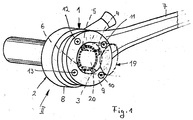
- the cutting head 1 shown in FIGS. 1 and 2 has one Cutting jaw holder 2, preferably in the known manner four cutting jaws 3 to 6 arranged diametrically to one another (Fig. 1) are provided.
- the cutting head 1 is used for cutting of threads on pipes, especially pipe ends, and is in a Inclusion of a ratchet lever 7 used with which the cutting head 1 is rotatably driven in a known manner.
- the ratchet lever 7 sits on a cutting head half 8, over the end face 15 one end of a tubular guide 14 for the tube projects axially.
- the cutting head 1 is in the usual way on pushed out of the wall 16 protruding tube end 17 that his ratchet lever 7 is adjacent to the wall 16. With the axially over the Cutting head 1 projecting guide 14, the cutting head is easy Center on the pipe end 17. Since the guide 14, if necessary interrupted until it reaches the cutting jaws 3 to 6 a thread clean on the pipe end 17 without difficulty to cut. The cutting head 1 can only be easily on that Push tube end 17 when it comes to dimension a out of wall 16 protrudes. This dimension a is so large that after completing the thread cutting the ratchet lever 7 is still at a distance from the wall 16.
- the cutting head 1 If the protrusion of the pipe end is smaller than the dimension a (Fig. 4), can the cutting head 1 only in a 180 ° rotated position on the Pipe end 17 are inserted, in which the ratchet lever 7 the side of the cutting head 1 facing away from the wall 16 and the cutting jaws 3 to 6 are implemented. Area 18 the wall 16 around the pipe end 17 is knocked out so that despite the smaller overhang on the pipe end 17, a thread can be cut. It is with conventional cutting heads not or only extremely difficult, a clean one in this twisted position To cut threads. This is due to the fact that the Cutting jaws 3 to 6 are close to the end face of the cover part 9 (Fig. 2). This is a guide of the cutting head 1, the the cover part 9 is placed on the pipe end 17, not possible.
- the cutting head 1 To safely guide the cutting head 1 in the rotated position to ensure on the pipe end 17, the cutting head 1 a guide element 19. It is preferably designed as a socket at one end of the cutting head 1 into an annular opening 22 of the cover part 9 is inserted. In Fig. 1 is the guide element 19 only shown schematically for reasons of clarity.
- the guide element 19 preferably has an outer diameter tapered end 21, with which it in the ring opening 22nd the cover part 9 is inserted.
- the guide element is preferably 19 held in the cover part 9 with a press fit.
- the guide element 19 has a circumferential outer ring shoulder 23, which is about a third of the length the guide element 19 extends. It protrudes axially over the cover part 9 and serves to guide and center the pipe end 17th
- the guide element 19 can, for example, reduce weight several circumferentially spaced one behind the other Have breakthroughs.
- the guide element 19 can also be welded to the cover part 9, soldered, glued or the like, but also in one piece can be formed with it. Finally, the guide element 19 also detachable with the cover part, for example by screwing, a snap, clamp or snap connection or the like, be connected.
- the guide element 19 is a simple and lightweight Is component, the guide costs the manufacturing costs not significantly increased and the handling of the cutting head 1 not affected.
- the guide member 19 has the same inner diameter as that Guide 14 so that reliable guidance and centering during threading is guaranteed.
- the guide element 19 can be made of any suitable material, in particular Plastic.
- the guide element 19 can also be provided with a cutting head that is part of an electrical tapping clip which the cutting head is driven to rotate by a motor.
Landscapes
- Engineering & Computer Science (AREA)
- Mechanical Engineering (AREA)
- Sawing (AREA)
- Basic Packing Technique (AREA)
- Sampling And Sample Adjustment (AREA)
- Magnetic Heads (AREA)
- Glass Compositions (AREA)
Abstract
Description
Die Erfindung betrifft einen Schneidkopf nach dem Oberbegriff des
Anspruches 1.The invention relates to a cutting head according to the preamble of
Mit solchen Schneidköpfen werden beispielsweise auf Rohrenden von in einer Wand verlegten Rohren Gewinde geschnitten. Üblicherweise wird der Schneidkopf so auf das aus der Wand ragende Rohrende gesteckt, daß ein Ratschenhebel, in den der Schneidkopf eingesetzt wird, benachbart zur Wand liegt. Beim Schneiden des Gewindes wird der Schneidkopf auf dem überstehenden Rohrende abgestützt. Häufig ist jedoch das über die Wand überstehende Rohrende nur kurz, so daß der Schneidkopf um 180° gedreht von der anderen Seite her auf das Rohr aufgesetzt und die Schneidbacken im Schneidkopf entsprechend umgesetzt werden müssen. Das Deckelteil liegt dann benachbart zur Wand, während der Ratschenhebel auf der von der Wand abgewandten Seite des Schneidkopfes liegt. In dieser verdrehten Lage ist aber eine Führung und/oder Zentrierung auf dem Rohrende nicht möglich, so daß ein Gewinde nicht oder nur mit großem Aufwand geschnitten werden kann. In diesem Fall ragt nur ein kurzes Rohrstück in den Schneidkopf, so daß dieser auf dem Rohrende nicht einwandfrei abgestützt und damit das Gewinde nicht zentrisch geschnitten werden kann.With such cutting heads, for example, on pipe ends cut threads from pipes laid in a wall. Usually the cutting head is thus on the pipe end protruding from the wall inserted that a ratchet lever into which the cutting head is inserted is adjacent to the wall. When cutting the thread the cutting head is supported on the protruding pipe end. Often, however, is the pipe end protruding over the wall only briefly, so that the cutting head rotated 180 ° from the other Mounted on the side of the tube and the cutting jaws in the Cutting head must be implemented accordingly. The lid part is then adjacent to the wall, while the ratchet lever on the side of the cutting head facing away from the wall. In this twisted position is a guide and / or centering on the Pipe end not possible, so that a thread is not or only with a large Effort can be cut. In this case, only protrudes short piece of pipe into the cutting head, so that this on the pipe end not properly supported and therefore the thread is not can be cut centrally.
Der Erfindung liegt die Aufgabe zugrunde, einen Schneidkopf dieser Art so auszubilden, daß er auch dann einwandfrei auf dem zu bearbeitenden Rohrende abgestützt wird, wenn es nur wenig übersteht und daher der Schneidkopf in umgekehrter Lage auf das Rohrende aufgesetzt werden muß.The invention has for its object a cutting head this Type in such a way that he can then be perfectly processed Pipe end is supported if it protrudes little and therefore the cutting head in an inverted position on the pipe end must be put on.
Diese Aufgabe wird bei einem Schneidkopf der gattungsbildenden Art
erfindungsgemäß mit den kennzeichnenden Merkmalen des Anspruches
1 gelöst.This task is performed with a cutting head of the generic type
according to the invention with the characterizing features of the
Infolge der erfindungsgemäßen Ausbildung weist der Schneidkopf am deckelseitigen Ende das Führungselement auf. Dadurch wird auch dann, wenn der Schneidkopf gegenüber seiner üblichen Lage um 180° verdreht an das Rohrende angesetzt wird, eine genaue Führung und Zentrierung gewährleistet, so daß sich ein sauberes Gewinde ohne Mühe schneiden läßt.As a result of the inventive design, the cutting head on cover-side end of the guide element. This will also then when the cutting head is over its usual position Is turned 180 ° to the pipe end, precise guidance and centering ensures that there is a clean thread can be easily cut.
Weitere Merkmale der Erfindung ergeben sich aus den weiteren Ansprüchen, der Beschreibung und den Zeichnungen.Further features of the invention result from the further claims, the description and the drawings.
Die Erfindung wird nachstehend anhand eines in den Zeichnungen dargestellten Ausführungsbeispieles näher beschrieben. Es zeigt:
- Fig. 1
- einen erfindungsgemäßen Schneidkopf mit einem Ratschenhebel in perspektivischer Darstellung,
- Fig. 2
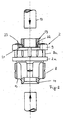
- den Schneidkopf nach Fig. 1 teilweise im Axialschnitt und teilweise in Ansicht ohne den Ratschenhebel,
- Fig. 3
- in schematischer Darstellung den Schneidkopf gemäß den Fig. 1 und 2, der an einem über eine Wand vorstehenden Rohrende zum Schneiden eines Gewindes angesetzt ist, wobei der Ratschenhebel benachbart zur Wand liegt,
- Fig. 4
- den Schneidkopf in einer Darstellung entsprechend Fig. 3, jedoch in einer um 180° verdrehten Lage.
- Fig. 1
- a cutting head according to the invention with a ratchet lever in a perspective view,
- Fig. 2
- 1 partly in axial section and partly in view without the ratchet lever,
- Fig. 3
- 1 and 2, which is attached to a pipe end projecting over a wall for cutting a thread, the ratchet lever being adjacent to the wall,
- Fig. 4
- the cutting head in a representation corresponding to FIG. 3, but in a position rotated by 180 °.
Der in den Fig. 1 und 2 dargestellte Schneidkopf 1 hat einen
Schneidbackenhalter 2, in dem in bekannter Weise vorzugsweise
vier jeweils diametral zueinander angeordnete Schneidbacken 3 bis 6
(Fig. 1) vorgesehen sind. Der Schneidkopf 1 dient zum Schneiden
von Gewinden auf Rohren, insbesondere Rohrenden, und wird in eine
Aufnahme eines Ratschenhebels 7 eingesetzt, mit dem der Schneidkopf
1 in bekannter Weise drehbar abgetrieben wird. Der Ratschenhebel
7 sitzt auf einer Schneidkopfhälfte 8, über deren Stirnseite 15
das eine Ende einer rohrförmigen Führung 14 für das Rohr axial ragt.The
Etwa in halber Länge weist der Schneidkopf 1 einen Ringbund 2a
auf. Auf der Stirnfläche der anderen Schneidkopfhälfte 8a sitzt ein
Abschlußring oder Deckelteil 9, das im Ausführungsbeispiel von vier
axial angeordneten Schrauben 10 bis 13 am Schneidbackenhalter
befestigt ist.About half the length of the
Wie Fig. 3 zeigt, wird der Schneidkopf 1 in üblicher Weise so auf ein
aus der Wand 16 ragendes Rohrende 17 geschoben, daß sein Ratschenhebel
7 benachbart zur Wand 16 liegt. Mit der axial über den
Schneidkopf 1 ragenden Führung 14 läßt sich der Schneidkopf einfach
auf dem Rohrende 17 zentrieren. Da die Führung 14, gegebenenfalls
unterbrochen, bis zu den Schneidbacken 3 bis 6 reicht, läßt
sich auf dem Rohrende 17 ohne Schwierigkeiten ein Gewinde sauber
schneiden. Der Schneidkopf 1 läßt sich nur dann problemlos auf das
Rohrende 17 schieben, wenn es um das Maß a aus der Wand 16
ragt. Dieses Maß a ist so groß, daß nach Beendigung des Gewindeschneidens
der Ratschenhebel 7 noch Abstand von der Wand 16 hat.3 shows, the
Ist der Überstand des Rohrendes kleiner als das Maß a (Fig. 4), kann
der Schneidkopf 1 nur in einer um 180° gedrehten Lage auf das
Rohrende 17 gesteckt werden, in der sich der Ratschenhebel 7 auf
der von der Wand 16 abgewandten Seite des Schneidkopfes 1 befindet
und die Schneidbacken 3 bis 6 umgesetzt sind. Der Bereich 18
der Wand 16 um das Rohrende 17 wird herausgeschlagen, damit
trotz des kleineren Überstandes auf dem Rohrende 17 ein Gewinde
geschnitten werden kann. Bei herkömmlichen Schneidköpfen ist es
nicht oder nur äußerst schwierig, in dieser verdrehten Lage ein sauberes
Gewinde zu schneiden. Dies ist darauf zurückzuführen, daß die
Schneidbacken 3 bis 6 nahe an der Stirnseite des Deckelteiles 9 liegen
(Fig. 2). Dadurch ist eine Führung des Schneidkopfes 1, der mit
dem Deckelteil 9 voran auf das Rohrende 17 gesteckt wird, nicht
möglich.If the protrusion of the pipe end is smaller than the dimension a (Fig. 4), can
the
Um eine sichere Führung des Schneidkopfes 1 in der verdrehten Lage
auf dem Rohrende 17 zu gewährleisten, weist der Schneidkopf 1
ein Führungselement 19 auf. Es ist vorzugsweise als Buchse ausgebildet,
die an einem Ende des Schneidkopfes 1 in eine Ringöffnung
22 des Deckelteiles 9 eingesetzt ist. In Fig. 1 ist das Führungselement
19 aus Gründen der Übersichtlichkeit nur schematisch dargestellt.To safely guide the
Vorzugsweise weist das Führungselement 19 ein im Außendurchmesser
verjüngtes Ende 21 auf, mit dem es in die Ringöffnung 22
des Deckelteiles 9 eingesetzt ist. Vorzugsweise ist das Führungselement
19 im Deckelteil 9 mit Preßsitz gehalten. Im Bereich des verjüngten
Endes 21 weist das Führungselement 19 eine umlaufende
äußere Ringschulter 23 auf, die sich etwa über ein Drittel der Länge
der Führungselementes 19 erstreckt. Es ragt axial über das Deckelteil
9 und dient zur Führung und Zentrierung des Rohrendes 17.The
Das Führungselement 19 kann zur Gewichtsreduzierung beispielsweise
mehrere in Umfangsrichtung mit Abstand hintereinander liegende
Durchbrüche aufweisen. The
Das Führungselement 19 kann auch mit dem Deckelteil 9 verschweißt,
verlötet, verklebt oder dergleichen, aber auch einstückig
mit ihm ausgebildet sein Schließlich kann das Führungselement 19
mit dem Deckelteil auch lösbar, beispielsweise durch eine Verschraubung,
eine Rast-, Klemm- oder Schnappverbindung oder dergleichen,
verbunden sein.The
Mit dem Führungselement 19 wird selbst auf nur wenig aus der Wand
16 ragenden oder sogar innerhalb der Wand 16 liegenden Rohrenden
17 eine sichere Führung und ein einwandfreier Halt des Schneidkopfes
1 in der verdrehten Lage erreicht. Somit kann auch das Gewinde
einwandfrei geschnitten werden.With the
Da das Führungselement 19 ein einfaches und gewichtsmäßig leichtes
Bauteil ist, werden durch das Führungselement die Herstellungskosten
nicht nennenswert erhöht und die Handhabung des Schneidkopfes
1 nicht beeinträchtigt.Since the
Wenn das zu bearbeitende Rohrende 17 kleineren oder größeren
Rohrdurchmesser hat, wird ein entsprechender Schneidkopf mit einem
entsprechend angepaßten Führungselement 19 in den Ratschenhebel
7 eingesetzt.If the pipe end to be machined is 17 smaller or larger
Has a tube diameter, a corresponding cutting head with a
accordingly adapted
Das Führungselement 19 hat gleichen Innendurchmesser wie die
Führung 14, so daß eine zuverlässige Führung und Zentrierung während
des Gewindeschneidens gewährleistet ist. Das Führungselement
19 kann aus jedem geeigneten Werkstoff, insbesondere aus
Kunststoff, bestehen.The
Das Führungselement 19 kann auch bei einem Schneidkopf vorgesehen
sein, der Teil einer elektrischen Gewindeschneidkluppe ist, bei
der der Schneidkopf motorisch drehbar angetrieben wird.The
Claims (11)
dadurch gekennzeichnet, daß zur Abstützung des zu bearbeitenden Rohres (17) am deckelseitigen Ende wenigstens ein Führungselement (19) vorgesehen ist.Cutting head for tapping devices, such as tapping clips and the like, with tapping jaws which are arranged in a die holder which has a receiving opening into which the pipe ends to be machined can be inserted from both sides and in which a cover part is provided on one side,
characterized in that at least one guide element (19) is provided for supporting the pipe (17) to be machined at the end on the cover side.
dadurch gekennzeichnet, daß das Führungselement (19) am Deckelteil (9) angeordnet ist.Cutting head according to claim 1,
characterized in that the guide element (19) is arranged on the cover part (9).
dadurch gekennzeichnet, daß das Führungselement (19) ein im Außendurchmesser verjüngtes Ende (21) aufweist, mit dem es in das Deckelteil (9) ragt.Cutting head according to claim 1 or 2,
characterized in that the guide element (19) has an end (21) tapering in outer diameter, with which it projects into the cover part (9).
dadurch gekennzeichnet, daß das verjüngte Ende (21) des Führungselementes (19) eine am Außenumfang des Führungselementes (19) vorgesehene Schulter (23) aufweist. Cutting head according to claim 3,
characterized in that the tapered end (21) of the guide element (19) has a shoulder (23) provided on the outer circumference of the guide element (19).
dadurch gekennzeichnet, daß die Länge des verjüngten Endes (21) etwa gleich einem Drittel der Länge des Führungselementes (19) entspricht.Cutting head according to claim 3 or 4,
characterized in that the length of the tapered end (21) corresponds approximately to one third of the length of the guide element (19).
dadurch gekennzeichnet, daß das Führungselement (19) mit Preßsitz im Schneidkopf (1) gehalten ist.Cutting head according to one of claims 1 to 5,
characterized in that the guide element (19) is held with a press fit in the cutting head (1).
dadurch gekennzeichnet, daß das Führungselement (19) mit dem Schneidkopf (1) unlösbar verbunden ist.Cutting head according to one of claims 1 to 6,
characterized in that the guide element (19) is permanently connected to the cutting head (1).
dadurch gekennzeichnet, daß das Führungselement (19) einstückig mit dem Deckelteil (9) ausgebildet ist.Cutting head according to one of claims 1 to 6,
characterized in that the guide element (19) is formed in one piece with the cover part (9).
dadurch gekennzeichnet, daß das Führungselement (19) lösbar, vorzugsweise über eine Schraub-, Rast-, Klemmverbindung oder dgl., mit dem Deckelteil (9) verbunden ist.Cutting head according to one of claims 1 to 5,
characterized in that the guide element (19) is detachably, preferably via a screw, snap-in, clamp connection or the like, connected to the cover part (9).
dadurch gekennzeichnet, daß das Führungselement (19) hülsenförmig ausgebildet ist.Cutting head according to one of claims 1 to 9,
characterized in that the guide element (19) is sleeve-shaped.
dadurch gekennzeichnet, daß das Führungselement (19) axial über das Deckelteil (9) vorsteht.Cutting head according to one of claims 1 to 10,
characterized in that the guide element (19) projects axially beyond the cover part (9).
Applications Claiming Priority (2)
| Application Number | Priority Date | Filing Date | Title |
|---|---|---|---|
| DE29707468U DE29707468U1 (en) | 1997-04-25 | 1997-04-25 | Cutting head |
| DE29707468U | 1997-04-25 |
Publications (4)
| Publication Number | Publication Date |
|---|---|
| EP0875327A2 true EP0875327A2 (en) | 1998-11-04 |
| EP0875327A3 EP0875327A3 (en) | 2004-01-28 |
| EP0875327B1 EP0875327B1 (en) | 2005-06-29 |
| EP0875327B2 EP0875327B2 (en) | 2020-09-23 |
Family
ID=8039519
Family Applications (1)
| Application Number | Title | Priority Date | Filing Date |
|---|---|---|---|
| EP98105579.1A Expired - Lifetime EP0875327B2 (en) | 1997-04-25 | 1998-03-27 | Die |
Country Status (3)
| Country | Link |
|---|---|
| EP (1) | EP0875327B2 (en) |
| DE (2) | DE29707468U1 (en) |
| ES (1) | ES2245010T3 (en) |
Cited By (1)
| Publication number | Priority date | Publication date | Assignee | Title |
|---|---|---|---|---|
| US11077509B2 (en) | 2018-03-16 | 2021-08-03 | Milwaukee Electric Tool Corporation | Pipe threader |
Families Citing this family (1)
| Publication number | Priority date | Publication date | Assignee | Title |
|---|---|---|---|---|
| ES2948270A1 (en) * | 2022-02-15 | 2023-09-07 | Pardo Galvez Jose Luis | Forming process that provides complementary structural fibering in obtaining materials or construction elements in general (Machine-translation by Google Translate, not legally binding) |
Citations (2)
| Publication number | Priority date | Publication date | Assignee | Title |
|---|---|---|---|---|
| CH87411A (en) * | 1920-05-27 | 1920-12-01 | Schweizer & Cie | Thread cutting stock. |
| EP0249184A2 (en) * | 1986-06-12 | 1987-12-16 | Milancy Ltd Inc. | Device for cutting threads |
-
1997
- 1997-04-25 DE DE29707468U patent/DE29707468U1/en not_active Expired - Lifetime
-
1998
- 1998-03-27 DE DE59812888T patent/DE59812888D1/en not_active Expired - Lifetime
- 1998-03-27 ES ES98105579T patent/ES2245010T3/en not_active Expired - Lifetime
- 1998-03-27 EP EP98105579.1A patent/EP0875327B2/en not_active Expired - Lifetime
Patent Citations (2)
| Publication number | Priority date | Publication date | Assignee | Title |
|---|---|---|---|---|
| CH87411A (en) * | 1920-05-27 | 1920-12-01 | Schweizer & Cie | Thread cutting stock. |
| EP0249184A2 (en) * | 1986-06-12 | 1987-12-16 | Milancy Ltd Inc. | Device for cutting threads |
Cited By (1)
| Publication number | Priority date | Publication date | Assignee | Title |
|---|---|---|---|---|
| US11077509B2 (en) | 2018-03-16 | 2021-08-03 | Milwaukee Electric Tool Corporation | Pipe threader |
Also Published As
| Publication number | Publication date |
|---|---|
| EP0875327B2 (en) | 2020-09-23 |
| EP0875327B1 (en) | 2005-06-29 |
| DE59812888D1 (en) | 2005-08-04 |
| EP0875327A3 (en) | 2004-01-28 |
| DE29707468U1 (en) | 1997-06-12 |
| ES2245010T3 (en) | 2005-12-16 |
Similar Documents
| Publication | Publication Date | Title |
|---|---|---|
| EP0647496B1 (en) | Studs | |
| DE3730017C1 (en) | Device for pressing in and pulling out bearings or sleeves, in particular for axle bearings and / or wheel flange hubs on motor vehicles | |
| DE2256306A1 (en) | TENSION SLEEVE ARRANGEMENT | |
| DE2700465A1 (en) | THREAD TURNING CLUTCH | |
| EP0711948B1 (en) | Welding sleeve for connecting tubular parts of plastics | |
| DE9206321U1 (en) | Tool for bleeding hydraulic systems | |
| EP0875327A2 (en) | Die | |
| DE4409983B4 (en) | chamfering | |
| DE3940114C2 (en) | Connection fitting | |
| DE1199544B (en) | Fastening device, in particular for fastening facing panels | |
| DE1179889B (en) | Detachable pipe connection | |
| DE3827317A1 (en) | Apparatus for reversing the polarity of the biological radiation of liquids | |
| DD231519A1 (en) | GAS CAP FOR PROTECTIVE GASS WELDING BURNER | |
| DE19833860C2 (en) | Fastening device for a pasture fence insulator on a tubular pile | |
| DE19828746B4 (en) | Tour guide | |
| EP2008744A2 (en) | Tool coupling | |
| DE2936147C2 (en) | Frame for the temporary storage of bundles of fuel assemblies | |
| DE1603904C (en) | Device for attaching and loosening screw devices | |
| DE2743503A1 (en) | Chuck with spring segments locked by coned nut - has limited rotational travel of inner sleeve for easy release of tool | |
| DE7912752U1 (en) | FLEXIBLE INTERCHANGEABLE LOCKING DEVICE FOR A TAPERED BEARING CONNECTION OR THE LIKE. OF TUBULAR PARTS OF A LABORATORY DEVICE O.AE. | |
| DE19910769A1 (en) | Screwing tool for an air layer screw anchor | |
| DE1500988B1 (en) | Expanding dowel | |
| DE2250373C3 (en) | Battery connector | |
| DE8003678U1 (en) | THREADING DEVICE | |
| DE3644241A1 (en) | SCREW HOLDER |
Legal Events
| Date | Code | Title | Description |
|---|---|---|---|
| PUAI | Public reference made under article 153(3) epc to a published international application that has entered the european phase |
Free format text: ORIGINAL CODE: 0009012 |
|
| AK | Designated contracting states |
Kind code of ref document: A2 Designated state(s): AT BE CH DE DK ES FI FR GB GR IE IT LI LU MC NL PT SE |
|
| AX | Request for extension of the european patent |
Free format text: AL;LT;LV;MK;RO;SI |
|
| PUAL | Search report despatched |
Free format text: ORIGINAL CODE: 0009013 |
|
| AK | Designated contracting states |
Kind code of ref document: A3 Designated state(s): AT BE CH DE DK ES FI FR GB GR IE IT LI LU MC NL PT SE |
|
| AX | Request for extension of the european patent |
Extension state: AL LT LV MK RO SI |
|
| RIC1 | Information provided on ipc code assigned before grant |
Ipc: 7B 23G 5/10 B Ipc: 7B 23G 5/04 A |
|
| 17P | Request for examination filed |
Effective date: 20040706 |
|
| AKX | Designation fees paid |
Designated state(s): BE DE ES FR IT |
|
| GRAP | Despatch of communication of intention to grant a patent |
Free format text: ORIGINAL CODE: EPIDOSNIGR1 |
|
| GRAS | Grant fee paid |
Free format text: ORIGINAL CODE: EPIDOSNIGR3 |
|
| GRAA | (expected) grant |
Free format text: ORIGINAL CODE: 0009210 |
|
| AK | Designated contracting states |
Kind code of ref document: B1 Designated state(s): BE DE ES FR IT |
|
| REF | Corresponds to: |
Ref document number: 59812888 Country of ref document: DE Date of ref document: 20050804 Kind code of ref document: P |
|
| REG | Reference to a national code |
Ref country code: ES Ref legal event code: FG2A Ref document number: 2245010 Country of ref document: ES Kind code of ref document: T3 |
|
| PLBI | Opposition filed |
Free format text: ORIGINAL CODE: 0009260 |
|
| PG25 | Lapsed in a contracting state [announced via postgrant information from national office to epo] |
Ref country code: BE Free format text: LAPSE BECAUSE OF NON-PAYMENT OF DUE FEES Effective date: 20060331 |
|
| ET | Fr: translation filed | ||
| PLAX | Notice of opposition and request to file observation + time limit sent |
Free format text: ORIGINAL CODE: EPIDOSNOBS2 |
|
| 26 | Opposition filed |
Opponent name: ROTHENBERGER AG Effective date: 20060321 |
|
| PLAF | Information modified related to communication of a notice of opposition and request to file observations + time limit |
Free format text: ORIGINAL CODE: EPIDOSCOBS2 |
|
| PLBB | Reply of patent proprietor to notice(s) of opposition received |
Free format text: ORIGINAL CODE: EPIDOSNOBS3 |
|
| BERE | Be: lapsed |
Owner name: REMS-WERK CHRISTIAN FOLL UND SOHNE G.M.B.H. & CO Effective date: 20060331 |
|
| PG25 | Lapsed in a contracting state [announced via postgrant information from national office to epo] |
Ref country code: IT Free format text: LAPSE BECAUSE OF NON-PAYMENT OF DUE FEES Effective date: 20100327 |
|
| PGRI | Patent reinstated in contracting state [announced from national office to epo] |
Ref country code: IT Effective date: 20110616 |
|
| PLAB | Opposition data, opponent's data or that of the opponent's representative modified |
Free format text: ORIGINAL CODE: 0009299OPPO |
|
| R26 | Opposition filed (corrected) |
Opponent name: ROTHENBERGER AG Effective date: 20060321 |
|
| PG25 | Lapsed in a contracting state [announced via postgrant information from national office to epo] |
Ref country code: DE Free format text: LAPSE BECAUSE OF NON-PAYMENT OF DUE FEES Effective date: 20111001 |
|
| REG | Reference to a national code |
Ref country code: FR Ref legal event code: PLFP Year of fee payment: 19 |
|
| APBM | Appeal reference recorded |
Free format text: ORIGINAL CODE: EPIDOSNREFNO |
|
| APBP | Date of receipt of notice of appeal recorded |
Free format text: ORIGINAL CODE: EPIDOSNNOA2O |
|
| APAH | Appeal reference modified |
Free format text: ORIGINAL CODE: EPIDOSCREFNO |
|
| APBQ | Date of receipt of statement of grounds of appeal recorded |
Free format text: ORIGINAL CODE: EPIDOSNNOA3O |
|
| REG | Reference to a national code |
Ref country code: FR Ref legal event code: PLFP Year of fee payment: 20 |
|
| PGFP | Annual fee paid to national office [announced via postgrant information from national office to epo] |
Ref country code: FR Payment date: 20170123 Year of fee payment: 20 |
|
| PGFP | Annual fee paid to national office [announced via postgrant information from national office to epo] |
Ref country code: ES Payment date: 20170310 Year of fee payment: 20 Ref country code: IT Payment date: 20170314 Year of fee payment: 20 |
|
| PGFP | Annual fee paid to national office [announced via postgrant information from national office to epo] |
Ref country code: DE Payment date: 20170525 Year of fee payment: 20 |
|
| REG | Reference to a national code |
Ref country code: DE Ref legal event code: R071 Ref document number: 59812888 Country of ref document: DE |
|
| APBU | Appeal procedure closed |
Free format text: ORIGINAL CODE: EPIDOSNNOA9O |
|
| REG | Reference to a national code |
Ref country code: ES Ref legal event code: FD2A Effective date: 20200724 |
|
| PUAH | Patent maintained in amended form |
Free format text: ORIGINAL CODE: 0009272 |
|
| STAA | Information on the status of an ep patent application or granted ep patent |
Free format text: STATUS: PATENT MAINTAINED AS AMENDED |
|
| 27A | Patent maintained in amended form |
Effective date: 20200923 |
|
| AK | Designated contracting states |
Kind code of ref document: B2 Designated state(s): BE DE ES FR IT |
|
| REG | Reference to a national code |
Ref country code: DE Ref legal event code: R102 Ref document number: 59812888 Country of ref document: DE |
|
| PG25 | Lapsed in a contracting state [announced via postgrant information from national office to epo] |
Ref country code: ES Free format text: LAPSE BECAUSE OF EXPIRATION OF PROTECTION Effective date: 20180328 |