EP0873263B1 - Continuous strip of detachably interconnected folded products - Google Patents
Continuous strip of detachably interconnected folded products Download PDFInfo
- Publication number
- EP0873263B1 EP0873263B1 EP96904681A EP96904681A EP0873263B1 EP 0873263 B1 EP0873263 B1 EP 0873263B1 EP 96904681 A EP96904681 A EP 96904681A EP 96904681 A EP96904681 A EP 96904681A EP 0873263 B1 EP0873263 B1 EP 0873263B1
- Authority
- EP
- European Patent Office
- Prior art keywords
- products
- strip
- consecutive
- envelopes
- interconnected
- Prior art date
- Legal status (The legal status is an assumption and is not a legal conclusion. Google has not performed a legal analysis and makes no representation as to the accuracy of the status listed.)
- Expired - Lifetime
Links
Images


Classifications
-
- B—PERFORMING OPERATIONS; TRANSPORTING
- B65—CONVEYING; PACKING; STORING; HANDLING THIN OR FILAMENTARY MATERIAL
- B65D—CONTAINERS FOR STORAGE OR TRANSPORT OF ARTICLES OR MATERIALS, e.g. BAGS, BARRELS, BOTTLES, BOXES, CANS, CARTONS, CRATES, DRUMS, JARS, TANKS, HOPPERS, FORWARDING CONTAINERS; ACCESSORIES, CLOSURES, OR FITTINGS THEREFOR; PACKAGING ELEMENTS; PACKAGES
- B65D27/00—Envelopes or like essentially-rectangular containers for postal or other purposes having no structural provision for thickness of contents
- B65D27/10—Chains of interconnected envelopes
Definitions
- This invention relates to a continuous strip of detachable consecutive interconnected products, obtained through folding, notably envelopes, bags, files, cases, foldable packing material, etc.
- US-A-4,497,509 discloses a continuous business form for use in automatic mailing systems. Envelopes are attached to a continuous strip of paper by means of an adhesive strip. It is rather cumbersome to attach the envelopes to the strip before the thus constituted form can be printed.
- the invention inter alia aims at remedying those flaws in a very simple and effective way and at offering a continuous strip of detachable interconnected products, the visible edges of which, for instance, when they are separated, are completely finished in such a way that, as far as finishing and aspect is concerned, they entirely correspond to the ones which are manufactured separately one by one and that they are hardly distinguishable from them, and this, in spite of the envelopes originally being made from a continuous strip, in a somewhat analogous way to the first application set forth in patent GB-A-567925.
- two consecutive products in the continuous strip are interconnected by a joint formed by a section of this strip not being part of the products themselves and being connected, in a detachable way, through successive lines of demarcation, to each of those two consecutive products, in such a way that, on removing the joint, the said two consecutive products are completely severed.
- At least part of the joints linking the consecutive products are attached to a common carrier in such a way that, together with the carrier, they may be severed from the other products through one single operation.
- a joint extends from the free edge of a so-called end area of a product of that strip to a so-called initial area of material of the consecutive product of the strip.
- the closing flap forms the said initial area and the back portion the said end area.
- the joints stretch out beyond the front portions of the products, in such a way that it is possible to print those joints in a similar way to and together with the products which are interconnected through the latter.
- the invention also pertains to a process as claimed in claim 7 for manufacturing a continuous strip of products produced through folding, consecutive series of areas of material being constituted, which are separated by folding lines transverse to the longitudinal direction of that strip, and two adjacent series of such areas of material being interconnected by division lines through a joint, a product out of every series of areas of material being constituted by joining the said areas through folding them round the said folding lines.
- Figure 1 is a plan view of consecutive series of areas of material.
- Figure 2 provides a schematic drawing of how envelopes are formed, according to the invention, from series of areas of material from figure 1.
- Figure 3 represents a schematic plan view of a strip with three envelopes according to the invention.
- Figure 4 represents the bottom view of the strip from figure 3.
- Figure 5 represents a strip of three envelopes, according to the invention, with a joint.
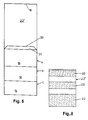
- Figure 6 provides a schematic perspective drawing of a strip, according to the invention, with three envelopes.
- Figure 7 represents a cross section according to the line VII-VII from figure 3.
- Figure 8 schematically represents a severed joint.
- Figure 9 provides a schematic plan view of consecutive series of areas of material provided with bands for pin-type feeding.
- Figure 10 represents a plan view of two parallel series of areas of material.
- a basic form 12 from which envelops are made is being cut out of a continuous strip of material, preferably a strip of paper, cardboard or plastic, as represented in figure 1, along the lines 10 in the longitudinal direction of this strip.
- the hatched zones 11 thus are removed from the sides of the strip.
- folding lines 13, 14 and 15 as well as the folding division lines 18 are being applied to this basic form 12.
- the folding lines 13 and 14 are extending transverse to the length of the strip and right across the width of basic form 12, whereas the folding lines 15 are extending along the longitudinal direction of this basic form 12.
- Folding lines 13, 14 and 15 are delineating front side 16 of an envelope. Folding lines 15 are separating side flaps 17 from this front side 16.
- Back 19 of an envelope is delineated, on the one hand, by a folding division line 18 and a folding line 14, and, on the other hand, by lines 10 or, accordingly, the longitudinal edge of the basic form 12.
- a closing flap 21 has been provided. This closing flap is being delineated by a folding line 13 and a division line 20.
- a joint 22 is being constituted, connecting two consecutive envelopes and being delineated by a division line 20 and the subsequent folding division line 18.
- the basic form 12 contains consecutive series of areas of material, each series of those areas being separated by division lines.
- the areas are being constituted by, successively, a back 19, a front side 16 and a closing flap 21, separated by folding lines and each allowing the folding of an envelope.
- Two consecutive series are interconnected by the aforementioned joint 22.
- three series A, B and C are being represented in basic form 12 of figure 1.
- the folding lines are provided to make the folding easier and more accurate in constituting the envelopes.
- those folding lines may possibly be left out and the folding of the envelopes requires then but one stage.
- the forming of the envelopes may therefore take place on the basis of a continuous strip of material, both the aforementioned basic form 12 being cut out and the envelopes being folded and glued all at one stage.
- the basic form represented in figure 1 may therefore show an almost unlimited length.
- Figure 2 shows the forming of the envelopes on the basis of a basic form 12 consisting of three series A, B and C of areas of material. Accordingly, a first envelope is being constituted by folding both side flaps 17 against the corresponding front band 16, round folding line 15. Next, an adhesive 17' is being applied to the side of those side flaps 17 turned away from the front side 16 . The corresponding back 19 is then being folded against the side flaps 17, round folding line 14, in order for back 19 to be attached to side flaps 17.
- the outside of the in-turned side flaps 17 and the inside of the in-tumed back 19 may also be joined in another way, according to the material used.
- joint 22, following back 19 is being folded simply round folding division line 18, in such a way that this joint 22 is now at the side of back 19 which is turned away from front side 16 of the envelope.
- the other series are folded analogously into envelopes.
- the closing flap 21 of an envelope formed from the first series of areas of material of a basic form 12 may be closed or not.
- Figure 3 shows the three front portions 16 of consecutive envelopes A, B and C formed in the abovementioned manner.
- Figure 4 represents the back 19 of the strip of envelopes constituted like that.
- the closing flaps 21 are being provided with an adhesive agent 21' allowing to attach the closing flaps 21, after they have been folded round folding line 13, to the corresponding backs 19, in order to close the envelopes.
- basic form 12 for the envelopes may be executed in various types, both for continuous series and for a certain amount of envelopes.
- joints 22 are also multifunctional. They may take any form without this affecting the quality of the envelopes.
- joints 22 in basic form 12 are made sufficiently broad, so that, in a strip of folded envelopes, in addition to the entire closing flaps 21, also part of joints 22 exceeds beyond the front portions 16 of the respective envelopes.
- those joints 22 may be printed simultaneously with the envelopes.
- This application is very useful when a counterfoil has to be preserved as a check of the printed envelopes or for filing purposes. In that way, those joints 22 may constitute such a counterfoil which not only exceeds from under the envelopes, but which may for instance also be filed, after having been printed simultaneously with the envelopes.
- the joints 22 being attached to a common carrier on the folding of the envelopes.
- This carrier may, for instance, be a paper strip which, on folding the envelopes, is progressively glued to the joints.
- This application has the advantage that the joints 22 remain fixed to the carrier, when the envelopes are removed. This mainly holds plus-points in filing the joints 22, when the latter constitute the above-mentioned counterfoils.
- the envelopes then may be separated from joints 22 through one single operation, by retaining a number of consecutive envelopes, on the one hand, and the said carrier, on the other hand.
- a unit, called envelope sheet is being formed.
- this envelope sheet may assume all possible sizes.
- the envelope sheet may be given a DIN A4 format, which may be printed by every standard printer. Those envelope sheets may be put per batch in the printer ; they will automatically be picked up one by one and printed. This makes it possible to handle whole series of envelopes in an ordinary standard printer without any further investment being required.
- a strip of paper 101 is being applied to the closing flap of the first envelope by non-permanent glue. In figure 7 such a strip 101 is being shown.
- strip 101 should exceed the sheet by about 1 to 1.5 cm. It would be more appropriate to glue strip 101 to the beginning of joint 22'.
- division lines 20 and folding division lines 18 hold but at a few places, i.e., when, for instance, they have been well perforated two or three times for a distance of 1 cm, or are thus provided with a division strip, while the rest of those lines has been cut loose, this offers the great advantage that the envelopes may be removed from the whole at one pull. Each one of the loose envelopes is fully finished.
- the envelope sheet which has been described above, is made of the same kind of paper, since it is formed from a continuous strip of paper, and therefore may be relatively heavy.
- joint 22' is being reduced to a strip of about 1 cm as from the end of the closing flap 21 of the first envelope.
- a much lighter type of paper, for instance onionskin, may be glued to that bit, in order to return joint 22' to its size as described above and to handle it further in the above-mentioned way.
- Figure 9 is a plan view of an adjusted basic form of envelopes for pin-type feeding.
- the hatched area in the drawing represents the severed material. Apart from that, the process to attain the finished product is identical to the method described above.
- the folding and division lines on the non-cut side bands 30 are also being applied, so that they are folded up in the course of the actual forming of the envelopes.
- an adhesive agent may be applied, on folding, to the places where the side bands 30 overlap or they may be connected in any other way. It would be proper to apply the perforations which must be provided for pin-type feeding devices, after the forming has been completed.
- Figure 10 shows a basic form 12 in which the envelopes are also put horizontally next to each other, so that, at the constitution according to the process as described above, two envelopes are being shaped simultaneously.
- Per horizontal series two in this drawing, it should be made sure that the side flaps 17 of each envelope are simultaneously folded inward and provided with adhesive agent 17' or a subsitute adhesive.
- the procedure of figure 9 pin-type feeding system
- more than two series of areas of material next to each other may be provided in one basic form 12.
- the strip of envelopes When the strip of envelopes, according to the invention, is applied to printers using the standard DIN A4 format, irrespective of whether the paper input takes place through a paper tray, through a cutsheetfeeder or page by page, the strip of paper (material) must be cut up (shaped) in pieces having a previously set length.
- the paper (material) treated according to the invention thus, as a finished product, provides several envelopes the number of which differs according to the desired envelope format. More in particular, a format of a DIN A4 sheet, after the folding and shaping of basic form 12, is being attained which may be applied to every printer using DIN A4 format, if the basic form is given the proper dimensions.
- the format of the envelope and therefore the number of envelopes per individually finished envelope sheet, with already formed envelopes may be adjusted by reducing or enlarging the joint 22.
- the strip differs in many ways from the technical state of affairs of the patents US-A-4 066 206 (PETERSON), FR-A-1 488 888 (GYSIN) and GB-A-567 924 (DAVIES).
- the requirement to apply the labels later on, one by one, to the envelopes still is a time-consuming and little effective process.
- automatic envelope machines still not only have trouble in coping with labelled envelopes, but also with window envelopes, which did provide a solution through skipping the stage of the separate addressing of the envelopes.
- Using labels or window envelopes then generally results in putting the items to be sent or to be distributed in the envelope by hand.
- the invention not only provides a solution to the above-mentioned problem.
- the end user can also print series of envelopes through his own printer, without this entailing any extra hardware expenses. He also still has a filing voucher per envelope, which holds an identification system. In some applications, still more extra information may be printed on this filing voucher.
- the invention also eliminates the sideways division lines at the front or the back of the envelopes, which were still apparent at envelopes that also were formed from a continuous strip of paper, while still being interconnected.
- the separate envelope may be formed from a continuous strip of paper and remains interconnected, while, in spite of that characteristic, it is being made fully ready for use and finished without there being any division lines or cutting marks on the edges of any part of the envelope. This is possible through leaving the chosen basic forms of the envelopes interconnected by means of a joint which, even after the forming of the finished product, is preserved as a joint.
Abstract
Description
Claims (7)
- Strip of detachable consecutive interconnected products, characterised in that these products are obtained by folding areas of material along folding lines (13,14,15), whereby two of these consecutive products are interconnected through a joint piece (22) formed by a section of this strip which is not part of the products themselves and links up detachably with each of those two consecutive products through perforated and/or folding lines (18,20) in such a way that, on removing this joint piece (22), the said consecutive products are entirely separated.
- Strip of detachable consecutive interconnected products according to claim 1, characterised in that at least part of the joints (22) connecting the consecutive products being attached to a common carrier (22') , in such a way that those joints (22), together with the carrier (22'), may be severed from the relevant products through one single operation.
- Strip of detachable consecutive interconnected products according to claim 1 or 2, characterised in that, when the concerned products have been formed from consecutive areas of material in the longitudinal direction of the strip of material, a joint (22) links up, through at least one folding line, a so-called end area of material of some product of this strip and a so-called initial area of material of the consecutive product of the strip.
- Strip of detachable consecutive interconnected products according to claim 3, characterised in that, when those products consist of envelopes with three consecutive areas of material which, successively, form a closing flap (21), a front side (16) and a back side (19) of an envelope, the closing flap (21) is constituting the initial area and the back side (19) is constituting the end area.
- Strip of detachable consecutive interconnected products according to one of claims 1 to 4, characterised in that the joints (22) are sufficiently broad, so that in said interconnected products part of the joints (22) exceeds beyond the front portions (16) of the respective products such that the joints (22) can be printed simultaneously with the products interconnected by means of the said joints (22).
- Strip of detachable consecutive interconnected products according to one of the claims 1 tot 5, characterised in that both sides of the strip are provided with a transport band (30) with successive perforations, made out of the same material as the products, whereby said transport band (30) only being attached sideways to the joints (22), the visible sides of the products as a result being entirely independent of those transport bands (30).
- Process for manufacturing a strip of at least two detachable interconnected products according to one of claims 1 to 6, characterised in that consecutive areas separated by folding and/or perforated lines transverse to the longitudinal direction of the strip of material are formed, whereby consecutive series of areas are separated by a joint (22) of this strip of material and whereby a product is formed from one series through joining said areas by folding them round said folding lines.
Applications Claiming Priority (3)
| Application Number | Priority Date | Filing Date | Title |
|---|---|---|---|
| BE9500194 | 1995-03-06 | ||
| BE9500194A BE1009176A3 (en) | 1995-03-06 | 1995-03-06 | Full ENVELOPES, BAGS, Farden, CASES AND / OR DERIVATIVES THEREOF AND / OR OTHER PRODUCTS IN SPITE OF SEPARATE COMPLETELY FINISHED YET STAY CONNECTED WITH EACH OTHER. |
| PCT/BE1996/000023 WO1996027531A1 (en) | 1995-03-06 | 1996-03-06 | Continuous strip of detachably interconnected folded products |
Publications (2)
| Publication Number | Publication Date |
|---|---|
| EP0873263A1 EP0873263A1 (en) | 1998-10-28 |
| EP0873263B1 true EP0873263B1 (en) | 2001-12-19 |
Family
ID=3888827
Family Applications (1)
| Application Number | Title | Priority Date | Filing Date |
|---|---|---|---|
| EP96904681A Expired - Lifetime EP0873263B1 (en) | 1995-03-06 | 1996-03-06 | Continuous strip of detachably interconnected folded products |
Country Status (10)
| Country | Link |
|---|---|
| US (1) | US5971260A (en) |
| EP (1) | EP0873263B1 (en) |
| AT (1) | ATE211100T1 (en) |
| AU (1) | AU4872396A (en) |
| BE (1) | BE1009176A3 (en) |
| DE (1) | DE69618239T2 (en) |
| DK (1) | DK0873263T3 (en) |
| ES (1) | ES2169228T3 (en) |
| PT (1) | PT873263E (en) |
| WO (1) | WO1996027531A1 (en) |
Families Citing this family (3)
| Publication number | Priority date | Publication date | Assignee | Title |
|---|---|---|---|---|
| US7100348B2 (en) * | 1996-03-06 | 2006-09-05 | Megaspirea N.V. | Continuous strip of detachably interconnected folded products |
| US6108003A (en) * | 1998-03-18 | 2000-08-22 | International Business Machines Corporation | Maintaining visibility and status indication of docked applications and application bars |
| US20040091660A1 (en) * | 2002-11-12 | 2004-05-13 | Southworth Company | Article of personal communication and a sheet material for separating such an article therefrom |
Family Cites Families (18)
| Publication number | Priority date | Publication date | Assignee | Title |
|---|---|---|---|---|
| US2464490A (en) * | 1943-08-04 | 1949-03-15 | Davies Herbert Vaughan | Continuous envelope assemblies |
| GB567924A (en) * | 1943-08-04 | 1945-03-08 | Herbert Vaughan Davies | Improvements in or relating to continuous envelope assemblies |
| US2610784A (en) * | 1949-10-18 | 1952-09-16 | Henry Beulah Louise | Continuously attached envelopes |
| US2776085A (en) * | 1954-07-09 | 1957-01-01 | Lawrence M Furey | Continuous multiple-section envelope assembly |
| US3028069A (en) * | 1961-02-13 | 1962-04-03 | Walter A Willis | Continuous web defining separable envelopes |
| US3332604A (en) * | 1966-03-10 | 1967-07-25 | Curtis 1000 Inc | Continuous envelope |
| FR1488888A (en) * | 1966-08-09 | 1967-07-13 | Endless belt of envelopes with perforated guide edges for addressing machines or the like | |
| US3559875A (en) * | 1969-11-06 | 1971-02-02 | Paul O Wilson | Continuous envelope form |
| US3626821A (en) * | 1969-11-10 | 1971-12-14 | Us Envelope Co | Method for making continuous form envelopes |
| US3790068A (en) * | 1971-05-20 | 1974-02-05 | Us Envelope Co | Continuous form envelope assembly |
| US4066206A (en) * | 1977-03-22 | 1978-01-03 | Uarco Incorporated | Continuous envelope assembly |
| US4497509A (en) * | 1982-09-16 | 1985-02-05 | Uarco Incorporated | Continuous business form for automated mailing |
| GB2145032B (en) * | 1983-08-19 | 1987-03-25 | Peter Charles Maitland Nissen | Continuous stationery |
| US5069384A (en) * | 1985-04-19 | 1991-12-03 | Bell Laurence J | Envelopes |
| AU616867B2 (en) * | 1985-04-19 | 1991-11-14 | Envelopments Pty Ltd | Envelopes |
| EP0226990B1 (en) * | 1985-12-16 | 1990-03-14 | EASTMAN KODAK COMPANY (a New Jersey corporation) | Envelopes constructed for ink jet printing |
| CA1271206A (en) * | 1987-03-06 | 1990-07-03 | Gaetan Bourbeau | Continuous strip envelopes |
| US4886205A (en) * | 1988-09-22 | 1989-12-12 | Uarco Incorporated | Easily feedable envelope construction |
-
1995
- 1995-03-06 BE BE9500194A patent/BE1009176A3/en not_active IP Right Cessation
-
1996
- 1996-03-06 DK DK96904681T patent/DK0873263T3/en active
- 1996-03-06 US US08/913,051 patent/US5971260A/en not_active Expired - Lifetime
- 1996-03-06 PT PT96904681T patent/PT873263E/en unknown
- 1996-03-06 AU AU48723/96A patent/AU4872396A/en not_active Abandoned
- 1996-03-06 DE DE69618239T patent/DE69618239T2/en not_active Expired - Lifetime
- 1996-03-06 EP EP96904681A patent/EP0873263B1/en not_active Expired - Lifetime
- 1996-03-06 WO PCT/BE1996/000023 patent/WO1996027531A1/en active IP Right Grant
- 1996-03-06 ES ES96904681T patent/ES2169228T3/en not_active Expired - Lifetime
- 1996-03-06 AT AT96904681T patent/ATE211100T1/en active
Also Published As
| Publication number | Publication date |
|---|---|
| EP0873263A1 (en) | 1998-10-28 |
| DE69618239T2 (en) | 2002-08-08 |
| ATE211100T1 (en) | 2002-01-15 |
| PT873263E (en) | 2002-06-28 |
| DK0873263T3 (en) | 2002-04-22 |
| ES2169228T3 (en) | 2002-07-01 |
| BE1009176A3 (en) | 1996-12-03 |
| DE69618239D1 (en) | 2002-01-31 |
| US5971260A (en) | 1999-10-26 |
| WO1996027531A1 (en) | 1996-09-12 |
| AU4872396A (en) | 1996-09-23 |
Similar Documents
| Publication | Publication Date | Title |
|---|---|---|
| US7587881B2 (en) | Continuous strip of detachably interconnected folded products | |
| US4706878A (en) | Self-mailer envelope | |
| CA1086272A (en) | Stuffed sealed envelope assembly | |
| US5296066A (en) | Multiweb perforated folded product and method | |
| MXPA96005101A (en) | Postal piece of seal by pressure folded e | |
| US6053855A (en) | Direct mail article with cover and one or more interior sheets and integral business reply envelope | |
| CA1245243A (en) | Business mailer | |
| US5015137A (en) | Booklet with central detachable business reply envelope and optional response device produced from an integral web and methods of production | |
| CA1303402C (en) | Direct mail article with mailable reply card | |
| EP0261843B1 (en) | Bifolded mailer with insert | |
| US5163612A (en) | Method of making a mailer with tear strip on outgoing and return envelopes | |
| US4726802A (en) | Mailing cover with reply envelope and response device from integral web | |
| US4492334A (en) | Tentless continuous mailer assembly | |
| US5263637A (en) | Self-mailer with return order envelope and the method for producing the same | |
| EP0873263B1 (en) | Continuous strip of detachably interconnected folded products | |
| EP0412484A2 (en) | Oversize laser mailer and method | |
| GB2219249A (en) | Book wrapping paper | |
| US5207592A (en) | Multiple part business form and related process | |
| NZ248836A (en) | Label in leaflet form; carrier sheet has adhesive rear surface protected by release sheet and leaflet attached to its front face; manufacture of labels | |
| CA1271206A (en) | Continuous strip envelopes | |
| AU653267B2 (en) | Multiple part business form and related process | |
| US4844329A (en) | Continuous mailer assembly | |
| EP0128738A2 (en) | Mailing wrapper with reply envelope and response device from integral web | |
| US4795193A (en) | Booklet with return envelope | |
| US5799979A (en) | Perforated cover |
Legal Events
| Date | Code | Title | Description |
|---|---|---|---|
| PUAI | Public reference made under article 153(3) epc to a published international application that has entered the european phase |
Free format text: ORIGINAL CODE: 0009012 |
|
| 17P | Request for examination filed |
Effective date: 19971219 |
|
| AK | Designated contracting states |
Kind code of ref document: A1 Designated state(s): AT BE CH DE DK ES FI FR GB IT LI NL PT SE |
|
| RBV | Designated contracting states (corrected) |
Designated state(s): AT BE CH DE DK ES FI FR GB GR IE IT LI LU MC NL PT SE |
|
| 17Q | First examination report despatched |
Effective date: 19990723 |
|
| GRAG | Despatch of communication of intention to grant |
Free format text: ORIGINAL CODE: EPIDOS AGRA |
|
| GRAG | Despatch of communication of intention to grant |
Free format text: ORIGINAL CODE: EPIDOS AGRA |
|
| GRAH | Despatch of communication of intention to grant a patent |
Free format text: ORIGINAL CODE: EPIDOS IGRA |
|
| GRAH | Despatch of communication of intention to grant a patent |
Free format text: ORIGINAL CODE: EPIDOS IGRA |
|
| GRAA | (expected) grant |
Free format text: ORIGINAL CODE: 0009210 |
|
| RBV | Designated contracting states (corrected) |
Designated state(s): AT BE CH DE DK ES FI FR GB IT LI NL PT SE |
|
| AK | Designated contracting states |
Kind code of ref document: B1 Designated state(s): AT BE CH DE DK ES FI FR GB IT LI NL PT SE |
|
| REF | Corresponds to: |
Ref document number: 211100 Country of ref document: AT Date of ref document: 20020115 Kind code of ref document: T |
|
| BECA | Be: change of holder's address |
Free format text: 20011219 *MERTENS LUC:REGELSBRUGGESTRAAT 85, B-9300 AALST |
|
| REG | Reference to a national code |
Ref country code: CH Ref legal event code: EP |
|
| REG | Reference to a national code |
Ref country code: GB Ref legal event code: IF02 |
|
| REF | Corresponds to: |
Ref document number: 69618239 Country of ref document: DE Date of ref document: 20020131 |
|
| REG | Reference to a national code |
Ref country code: CH Ref legal event code: NV Representative=s name: ISLER & PEDRAZZINI AG |
|
| REG | Reference to a national code |
Ref country code: DK Ref legal event code: T3 |
|
| ET | Fr: translation filed | ||
| REG | Reference to a national code |
Ref country code: PT Ref legal event code: TE4A Free format text: LUC MERTENS BE Effective date: 20020318 Ref country code: PT Ref legal event code: SC4A Free format text: AVAILABILITY OF NATIONAL TRANSLATION Effective date: 20020318 |
|
| REG | Reference to a national code |
Ref country code: ES Ref legal event code: FG2A Ref document number: 2169228 Country of ref document: ES Kind code of ref document: T3 |
|
| PLBE | No opposition filed within time limit |
Free format text: ORIGINAL CODE: 0009261 |
|
| STAA | Information on the status of an ep patent application or granted ep patent |
Free format text: STATUS: NO OPPOSITION FILED WITHIN TIME LIMIT |
|
| 26N | No opposition filed | ||
| REG | Reference to a national code |
Ref country code: CH Ref legal event code: PUEA Owner name: LUC MERTENS Free format text: LUC MERTENS#REGELSBRUGGESTRAAT 85#9300 AALST (BE) -TRANSFER TO- LUC MERTENS#REGELSBRUGGESTRAAT 85#9300 AALST (BE) $ HERSCH REICH#JACOB JACOBSSTRAAT 14#2018 ANTWERPEN (BE) |
|
| NLS | Nl: assignments of ep-patents |
Owner name: HERSCH REICH Effective date: 20050928 Owner name: LUC MERTENS Effective date: 20050928 |
|
| REG | Reference to a national code |
Ref country code: FR Ref legal event code: TQ |
|
| REG | Reference to a national code |
Ref country code: CH Ref legal event code: PCAR Free format text: ISLER & PEDRAZZINI AG;POSTFACH 1772;8027 ZUERICH (CH) |
|
| REG | Reference to a national code |
Ref country code: CH Ref legal event code: PUEA Owner name: UC MERTENS Free format text: LUC MERTENS#REGELSBRUGGESTRAAT 85#9300 AALST (BE) $ BURGERLIJKE MAATSCHAP FAMILIE MERTENS-SENS#BURGERMEESTER PORTMANSLAAN 67 A, BOX 6#9200 DENDERMONDE (BE) -TRANSFER TO- LUC MERTENS#REGELSBRUGGESTRAAT 85#9300 AALST (BE) $ HERSCH REICH#JACOB JACOBSSTRAAT 14#2018 ANTWERPEN (BE) Ref country code: CH Ref legal event code: PUEA Owner name: UC MERTENS Free format text: LUC MERTENS#REGELSBRUGGESTRAAT 85#9300 AALST (BE) $ HERSCH REICH#JACOB JACOBSSTRAAT 14#2018 ANTWERPEN (BE) -TRANSFER TO- LUC MERTENS#REGELSBRUGGESTRAAT 85#9300 AALST (BE) $ BURGERLIJKE MAATSCHAP FAMILIE MERTENS-SENS#BURGERMEESTER PORTMANSLAAN 67 A, BOX 6#9200 DENDERMONDE (BE) Ref country code: CH Ref legal event code: PK Free format text: DIE AM 5.5.2010 EINGETRAGENE TEILUEBERTRAGUNG VON HERSCH REICH, BE-2018 ANTWERPEN AUF BURGERLIJKE MAATSCHAAP FAMILIE MERTENS-SENS, BE-9200 DENDERMONDE, |
|
| PGFP | Annual fee paid to national office [announced via postgrant information from national office to epo] |
Ref country code: DE Payment date: 20100429 Year of fee payment: 15 |
|
| REG | Reference to a national code |
Ref country code: CH Ref legal event code: PUEA Owner name: LUC MERTENS Free format text: LUC MERTENS#REGELSBRUGGESTRAAT 85#9300 AALST (BE) $ HERSCH REICH#JACOB JACOBSSTRAAT 14#2018 ANTWERPEN (BE) -TRANSFER TO- LUC MERTENS#REGELSBRUGGESTRAAT 85#9300 AALST (BE) $ BURGERLIJKE MAATSCHAP FAMILIE MERTENS-SENS#BURGERMEESTER PORTMANSLAAN 67 A, BOX 6#9200 DENDERMONDE (BE) |
|
| PGFP | Annual fee paid to national office [announced via postgrant information from national office to epo] |
Ref country code: CH Payment date: 20110615 Year of fee payment: 16 |
|
| REG | Reference to a national code |
Ref country code: PT Ref legal event code: MM4A Free format text: LAPSE DUE TO NON-PAYMENT OF FEES Effective date: 20110906 |
|
| REG | Reference to a national code |
Ref country code: PT Ref legal event code: NF4A Free format text: RESTITUTIO IN INTEGRUM Effective date: 20110912 |
|
| PGFP | Annual fee paid to national office [announced via postgrant information from national office to epo] |
Ref country code: DK Payment date: 20110906 Year of fee payment: 16 |
|
| PGRI | Patent reinstated in contracting state [announced from national office to epo] |
Ref country code: PT Effective date: 20110912 |
|
| PGFP | Annual fee paid to national office [announced via postgrant information from national office to epo] |
Ref country code: FI Payment date: 20110920 Year of fee payment: 16 Ref country code: FR Payment date: 20111005 Year of fee payment: 16 Ref country code: ES Payment date: 20110906 Year of fee payment: 16 Ref country code: GB Payment date: 20110923 Year of fee payment: 16 Ref country code: SE Payment date: 20110905 Year of fee payment: 16 Ref country code: PT Payment date: 20110905 Year of fee payment: 16 Ref country code: AT Payment date: 20110926 Year of fee payment: 16 |
|
| PGFP | Annual fee paid to national office [announced via postgrant information from national office to epo] |
Ref country code: IT Payment date: 20110923 Year of fee payment: 16 Ref country code: NL Payment date: 20110927 Year of fee payment: 16 |
|
| REG | Reference to a national code |
Ref country code: DE Ref legal event code: R082 Ref document number: 69618239 Country of ref document: DE Representative=s name: MICHALSKI HUETTERMANN & PARTNER PATENTANWAELTE, DE |
|
| PGFP | Annual fee paid to national office [announced via postgrant information from national office to epo] |
Ref country code: BE Payment date: 20110923 Year of fee payment: 16 |
|
| REG | Reference to a national code |
Ref country code: DE Ref legal event code: R082 Ref document number: 69618239 Country of ref document: DE Representative=s name: MICHALSKI HUETTERMANN & PARTNER PATENTANWAELTE, DE Effective date: 20120103 Ref country code: DE Ref legal event code: R081 Ref document number: 69618239 Country of ref document: DE Owner name: REICH, HERSCH, BE Free format text: FORMER OWNERS: MERTENS, LUC, AALST, BE; REICH, HERSCH, ANTWERPEN, BE Effective date: 20120103 Ref country code: DE Ref legal event code: R081 Ref document number: 69618239 Country of ref document: DE Owner name: MERTENS, LUC, BE Free format text: FORMER OWNERS: MERTENS, LUC, AALST, BE; REICH, HERSCH, ANTWERPEN, BE Effective date: 20120103 Ref country code: DE Ref legal event code: R081 Ref document number: 69618239 Country of ref document: DE Owner name: MERTENS, LUC, BE Free format text: FORMER OWNER: LUC MERTENS,HERSCH REICH, , BE Effective date: 20120103 Ref country code: DE Ref legal event code: R081 Ref document number: 69618239 Country of ref document: DE Owner name: REICH, HERSCH, BE Free format text: FORMER OWNER: LUC MERTENS,HERSCH REICH, , BE Effective date: 20120103 |
|
| REG | Reference to a national code |
Ref country code: PT Ref legal event code: MM4A Free format text: LAPSE DUE TO NON-PAYMENT OF FEES Effective date: 20120906 |
|
| BERE | Be: lapsed |
Owner name: REICH HERSCH Effective date: 20120331 Owner name: MERTENS LUC Effective date: 20120331 |
|
| REG | Reference to a national code |
Ref country code: NL Ref legal event code: V1 Effective date: 20121001 |
|
| REG | Reference to a national code |
Ref country code: SE Ref legal event code: EUG |
|
| PG25 | Lapsed in a contracting state [announced via postgrant information from national office to epo] |
Ref country code: FI Free format text: LAPSE BECAUSE OF NON-PAYMENT OF DUE FEES Effective date: 20120306 Ref country code: SE Free format text: LAPSE BECAUSE OF NON-PAYMENT OF DUE FEES Effective date: 20120307 |
|
| REG | Reference to a national code |
Ref country code: CH Ref legal event code: PL |
|
| REG | Reference to a national code |
Ref country code: DK Ref legal event code: EBP |
|
| GBPC | Gb: european patent ceased through non-payment of renewal fee |
Effective date: 20120306 |
|
| PG25 | Lapsed in a contracting state [announced via postgrant information from national office to epo] |
Ref country code: PT Free format text: LAPSE BECAUSE OF NON-PAYMENT OF DUE FEES Effective date: 20120906 |
|
| REG | Reference to a national code |
Ref country code: AT Ref legal event code: MM01 Ref document number: 211100 Country of ref document: AT Kind code of ref document: T Effective date: 20120306 |
|
| REG | Reference to a national code |
Ref country code: FR Ref legal event code: ST Effective date: 20121130 |
|
| PG25 | Lapsed in a contracting state [announced via postgrant information from national office to epo] |
Ref country code: GB Free format text: LAPSE BECAUSE OF NON-PAYMENT OF DUE FEES Effective date: 20120306 Ref country code: FR Free format text: LAPSE BECAUSE OF NON-PAYMENT OF DUE FEES Effective date: 20120402 Ref country code: AT Free format text: LAPSE BECAUSE OF NON-PAYMENT OF DUE FEES Effective date: 20120306 Ref country code: BE Free format text: LAPSE BECAUSE OF NON-PAYMENT OF DUE FEES Effective date: 20120331 Ref country code: CH Free format text: LAPSE BECAUSE OF NON-PAYMENT OF DUE FEES Effective date: 20120331 Ref country code: LI Free format text: LAPSE BECAUSE OF NON-PAYMENT OF DUE FEES Effective date: 20120331 |
|
| REG | Reference to a national code |
Ref country code: DE Ref legal event code: R119 Ref document number: 69618239 Country of ref document: DE Effective date: 20121002 |
|
| PG25 | Lapsed in a contracting state [announced via postgrant information from national office to epo] |
Ref country code: IT Free format text: LAPSE BECAUSE OF NON-PAYMENT OF DUE FEES Effective date: 20120306 |
|
| PG25 | Lapsed in a contracting state [announced via postgrant information from national office to epo] |
Ref country code: NL Free format text: LAPSE BECAUSE OF NON-PAYMENT OF DUE FEES Effective date: 20121001 |
|
| PG25 | Lapsed in a contracting state [announced via postgrant information from national office to epo] |
Ref country code: DK Free format text: LAPSE BECAUSE OF NON-PAYMENT OF DUE FEES Effective date: 20120331 |
|
| REG | Reference to a national code |
Ref country code: ES Ref legal event code: FD2A Effective date: 20130710 |
|
| PG25 | Lapsed in a contracting state [announced via postgrant information from national office to epo] |
Ref country code: ES Free format text: LAPSE BECAUSE OF NON-PAYMENT OF DUE FEES Effective date: 20120307 |
|
| PG25 | Lapsed in a contracting state [announced via postgrant information from national office to epo] |
Ref country code: DE Free format text: LAPSE BECAUSE OF NON-PAYMENT OF DUE FEES Effective date: 20121002 |