BACKGROUND OF THE INVENTION
This invention relates to a disc cartridge for an MD
(mini disc) or the like having a disc-like medium such as an
optical disc or the like received therein, and more particularly
to such a disc cartridge wherein an upper plate and a lower plate
are connected to each other through a center frame interposedly
arranged therebetween.
A record medium on which recording and reproducing of
data are carried out using magnetism or light is typically
received in a casing structure called a disc cartridge, resulting
in being charged in a recording and reproducing apparatus
provided with a device called a magnetic head or an optical
pickup device while being kept received in the casing structure.
The disc cartridge prevents dust or contaminant from adhering to
the record medium, to thereby contribute to an improvement in
operational reliability of the record medium.
For the purpose of carrying out recording and reproducing
of data on the record medium in the recording and reproducing
apparatus, it is required to keep positional relationship between
the record medium and the recording and reproducing device
constant to ensure reliability in the recording and reproducing
operation. To this end, it is of course required to stably
rotate the record medium. Thus, it is generally carried out to
adopt a means for providing a surface of the record medium with
satisfactory smoothness and flatness.
There are considered factors which deteriorate positional
relationship between the record medium and the recording and
reproducing device. The factors include vibration externally
applied to the recording and reproducing device, vibration
generated by a motor incorporated in the recording and
reproducing apparatus, and the like. A failure in adoption of
any suitable measure against such vibration leads to a failure in
satisfactory recording and reproducing. In particular, although
a vibration-proof measure is adopted in a recording and
reproducing apparatus mounted on an automobile or the like which
generates vibration of an increased magnitude, no vibration-proof
measure is taken in the disc cartridge itself.
Resin increased in specific gravity has been used for
providing a cartridge for a magnetic record medium such as a
magnetic tape with increased functionality and quality such as
increased sound reproducing characteristics, increased depth
characteristics and the like.
More particularly, Japanese Patent Application Laid-Open
Publication No. 325470/1993 proposes a magnetic record envelope
formed of thermoplastic resin containing of barium sulfate in an
amount of 1 to 30% by weight. Composite resin having barium
sulfate added thereto in such an amount has specific gravity
within a range of from 1.1 to 1.6. Also, Japanese Patent
Application Laid-Open Publication No. 307859/1993 discloses a
video tape cassette made of a composite resin material of 1.3 to
1.4 in specific gravity containing barium sulfate in an amount of
25 to 35% by weight. As a result of a study by the inventors, it
was found that specific gravity within the ranges described above
fails to permit the envelope and cassette to exhibit satisfactory
vibration-proof characteristics.
Japanese Patent Application Laid-Open Publication No.
119084/1988 discloses a cassette half made of a polypropylene
resin composition of 2 or more in specific gravity which contains
an inorganic reinforcing material in an amount of 45% by volume
of the composition. The organic reinforcing material contains
zinc oxide in an mount of from 20 to 100% by weight. Also,
Japanese Patent Application Laid-Open Publication No. 57182/1987
discloses a composite plastic material having at least one of
calcium carbonate and barium sulfate incorporated therein in an
amount of 45 to 65% by weight. The amount of such fillers to be
added is said to be determined depending on moldability of the
material by injection molding. As a result of a study thereon by
the inventors, it was found that an increase in flowability or
fluidity of the material or resin facilitates molding of an
article complicated in structure due to formation of a number of
fine ribs or the like such as a cartridge for a magnetic record
medium while providing the article with increased dimensional
accuracy and improved appearance and ensuring increased
productivity of the article. Also, it was found that the above-described
amount of addition of the fillers is excessive for a
composite resin material for a magnetic record medium cartridge.
Also, Japanese Patent Application Laid-Open Publication
No. 117768/1984 discloses a cassette made of a composite resin
material having specific gravity of from 1.5 to 2.2. The
publication teaches that zinc oxide, barium sulfate, lead sulfate
or the like may be used as an additive or filler for the
composite resin material and the amount of the additive or filler
may be adjusted within a range of from 40 to 80% by weight.
However, it fails to provide any example for illustrating the
teaching.
Further, techniques for constructing a cartridge into a
three-layer structure is disclosed in Japanese Patent Application
Laid-Open Publication No. 113466/1982, Japanese Patent
Application Laid-Open Publication No. 78478/1989 and Japanese
Utility Model Publication No. 13668/1982. More specifically,
Japanese Patent Application Laid-Open Publication No. 113466/1982
merely shows a disc cartridge in drawings thereof. It fails to
teach a structure of the disc cartridge. Japanese Patent
Application Laid-Open Publication No. 78478/1989 discloses a disc
cartridge constructed of a center frame made of a material
increased in rigidity and upper and lower plates made of resin.
However, it fails to consider vibration-proofness. Japanese
Utility Model Publication No. 13668/1982 discloses a tape
cartridge constructed of a center frame made of aluminum by die
casting and upper and lower plates made of resin. Unfortunately,
formation of the center frame by die casting deteriorates
productivity of the center frame and therefore the tape
cartridge.
A disc cartridge is generally required to exhibit
increased reliability in recording and reproducing of a signal.
For this purpose, it is required to form the disc cartridge with
highly increased configurational accuracy and dimensional
accuracy. Also, the disc cartridge is required to exhibit such
vibration-proofness as described above in order to stabilize
positional relationship between a recording and reproducing
device and a record medium. A disc cartridge is generally
constructed of two members called an upper half and a lower half,
which are formed by injection molding. More specifically, as
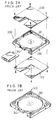
shown in Fig. 1, a disc cartridge 100 includes an upper half 110
and a lower half 120 which includes ribs 130 for defining a space
in which a record medium is received and ribs 140 for arranging
an erasure preventing member in the lower half 120. In order to
satisfactorily attain molding of the lower half 120 while
ensuring configurational and dimensional accuracy thereof, it is
required that resin used for the molding exhibits increased
flowability or fluidity.
Injection molding generally takes place by injecting a
molding resin material into a die. For injection molding of
resin deteriorated in flowability, it is required to increase a
temperature of the resin to increase flowability of the resin or
increase a pressure of the resin, to thereby force the resin into
the whole die. Unfortunately, a molded article thus formed is
deteriorated in both dimensional accuracy and configurational
accuracy. Thus, in order that an article such as a disc
cartridge having a complicated and fine structure is molded with
increased accuracy, it is highly required that the resin exhibits
satisfactory flowability or fluidity. More particularly, in
order to ensure operational reliability of a disc cartridge and
improve productivity thereof, it is essentially important to use
resin moldable as much as possible. Even a slight variation in
flowability of the resin substantially affects appearance and
dimensional characteristics of the disc cartridge, as well as
productivity thereof.
As will be noted from the foregoing, there have been made
a lot of proposals which attempt to ensure vibration proofness of
a disc cartridge by selection of specific gravity of a molding
material or resin and addition of a filler to the resin.
However, the prior art substantially fails to fully consider a
reduction in flowability or fluidity of the resin due to addition
of the filler thereto or a deterioration in moldability of the
resin, leading to a failure to provide a disc cartridge which is
capable of meeting requirements on both vibration proofness and
moldability.
Also, an increase in amount of the filler to be added to
the molding resin causes the disc cartridge to be brittle,
resulting in the disc cartridge being decreased in resistance to
shock.
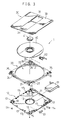
Now, the conventional disc cartridge of a three-piece
structure disclosed in Japanese Patent Application Laid-Open
Publication No. 78478/1989 described above will be described with
reference to Fig. 2A. The disc cartridge indicated at reference
numeral 200 includes an upper plate 230 and a lower plate 210
with a center frame 220 being interposedly arranged therebetween,
resulting in being constructed into a three-piece structure,
leading to an increase in rigidity. In the disc cartridge 200
thus constructed, a reduction in thickness thereof requires to
reduce a thickness of the center frame 220. Unfortunately, a
decrease in thickness of the center frame 200 deteriorates
flowability of resin during molding of the disc cartridge.
The center frame 220 has a recess 221 of a substantially
square-like shape defined therein for receiving a disc-like
record medium 240 therein. However, formation of the square-like
recess 221 in the center frame 220 causes corners of the center
frame 220 to be decreased in thickness, leading to a
deterioration in rigidity of the center frame 220. In order to
avoid such a problem, a center frame designated at reference
numeral 320 in Fig. 2B is provided, which is formed with a
circular recess 321 for receiving a disc-like record medium 240
therein. The circular recess 321 permits corners of the square-like
center frame 320 to be increased in thickness.
Unfortunately, this causes a thickness of a central portion of
the center frame to be reduced, to thereby still fail to ensure
satisfactory rigidity of the center frame 320.
Also, the disc cartridge disclosed in Japanese Patent
Application Laid-Open Publication No. 78478/1989 is so
constructed that the upper and lower plates are secured to the
center frame by means of screws. In addition, assembling of the
disc cartridge is carried out by mounting the center plate on the
lower plate to form a subassembly, incorporating the record
medium, a plug, a shutter lock and the like in the subassembly,
and mounting the upper plate on the subassembly.
Thus, in the disc cartridge disclosed, the upper and
lower plates of a square-like configuration are screwed to the
center frame of a square-like configuration. This results in the
disc cartridge being substantially identical with a disc
cartridge of a two-piece structure constructed of only an upper
plate and a lower plate. Thus, in order to increase rigidity of
the disc cartridge, it is required that the center frame is
formed of resin having a reinforcing material added thereto. For
the same purpose, it is also required that a region of the center
frame in which the disc-like record medium is received is
increased in thickness. Unfortunately, this causes an increase
in whole thickness of the center frame, as well as generation of
sink marks in a thin-wall region of the center frame, leading to
a deterioration in appearance. It would be considered to form
the center frame with lightening holes in order to avoid an
increase in thickness of the center frame and generation of the
sink marks. This causes a reduction in rigidity of the center
frame although it improves appearance of the center frame. The
center frame is subject to warpage depending on formation of the
lightening holes, resulting in configurational accuracy of the
center frame being deteriorated, leading to a failure in
satisfactory assembling of the disc cartridge.
SUMMARY OF THE INVENTION
The present invention has been made in view of the
foregoing disadvantages of the prior art.
Accordingly, it is an object of the present invention to
provide a disc cartridge which is capable of ensuring increased
reliability in operation thereof and increasing productivity
thereof.
It is another object of the present invention to provide
a disc cartridge of a three-piece structure which is capable of
increasing both formability and rigidity of a center frame.
It is a further object of the present invention to
provide a disc cartridge which is capable of increasing rigidity
of a center frame and preventing generation of sink marks on the
center frame and warpage of the center frame, resulting in
ensuring satisfactory assembling of the disc cartridge.
It is still another object of the present invention to
provide a disc cartridge which is capable of increasing
dimensional and configurational accuracy of the disc cartridge
while ensuring good appearance thereof.
In accordance with the present invention, a disc
cartridge is provided. The disc cartridge includes an upper
plate, a lower plate, and a center frame arranged between the
upper plate and the lower plate so as to join the upper plate and
lower plate to each other therethrough. The center frame is
constituted by a circumferential member of a square-like shape as
viewed in plan which is formed so as to continuously surround a
disc-like medium. The upper and lower plates are provided on
four corners thereof with fixing bosses, respectively, wherein
the fixing bosses of the upper plate and those of the lower plate
are arranged in a manner to be opposite to each other. The
center frame is formed on opposite surfaces thereof with fitting
recesses in which the bosses are fitted, respectively. Also, the
center frame is formed on each of four corners thereof with a
thin-wall portion having a reduced thickness of 50 to 80% based
on a whole thickness of the center frame.
In a preferred embodiment of the present invention, the
center frame is partly recessed in a surface thereof opposite to
the lower plate to provide the thin-wall portions.
In a preferred embodiment of the present invention, the
thin-wall portions are each arranged in a region of the center
frame between an outer peripheral portion of a respective one of
the four corners of the center frame and an inner peripheral
portion thereof so that the outer and inner peripheral portions
have the whole thickness.
In a preferred embodiment of the present invention, the
disc cartridge further includes an erasure preventing plug. The
center frame is provided in an outer surface thereof with a
cutout in which the erasure preventing plug is arranged. The
corner of the center frame in proximity to the cutout is so
arranged that a distal end thereof is positioned inside an outer
edge of the upper and lower plates.
In a preferred embodiment of the present invention, the
upper and lower plates and the center plate are integrally joined
together by means of screws threadedly inserted in the bosses and
fitting recesses.
In a preferred embodiment of the present invention, the
upper and lower plates and the center plate are integrally joined
together by bonding the bosses to the fitting recesses by
welding.
In a preferred embodiment of the present invention, at
least one of the upper and lower plates is provided thereon with
projections in a manner to be opposite to the thin-wall portions
of the center plate, to thereby enhance rigidity of the disc
cartridge.
In a preferred embodiment of the present invention, the
center frame has a circular receiving space defined therein in
which the disc-like medium is received. The circular receiving
space is defined by an inner peripheral surface of the center
frame. The center frame has gate positions for molding thereof
defined therein. The gate positions are each defined so as to be
angularly deviated from an intersection between the inner
peripheral surface of the center frame and a line defined by
connecting a center of the receiving space and a respective one
of corners of the center frame to each other.
In a preferred embodiment of the present invention, the
gate positions are defined in respective recesses formed in the
inner peripheral surface of the center frame.
In a preferred embodiment of the present invention, the
center frame is made of a composite resin material prepared by
mixing resin selected from the group consisting of acrylonitrile-butadiene-styrene
resin, polycarbonate resin, polystyrene resin
and polyamide resin with a metal powder.
In a preferred embodiment of the present invention, the
center frame is made of a composite resin material of 2.5 or more
in specific gravity prepared by mixing resin with a filler.
In a preferred embodiment of the present invention, the
center frame is formed with a volume of 20 to 60% based on a
combined volume of the upper and lower plates.
In a preferred embodiment of the present invention, the
filler contained in the composite resin material is an amount of
50 parts by volume or less based on 100 parts by volume of the
resin.
In a preferred embodiment of the present invention, the
filler is a tungsten powder. Alternatively, the filler may be a
stainless steel powder.
BRIEF DESCRIPTION OF THE DRAWINGS
These and other objects and many of the attendant
advantages of the present invention will be readily appreciated
as the same becomes better understood by reference to the
following detailed description when considered in connection with
the accompanying drawings; wherein:
DETAILED DESCRIPTION OF THE PREFERRED EMBODIMENTS
Now, a disc cartridge according to the present invention
will be described hereinafter with reference to Figs. 3 to 16,
wherein like reference numerals designate like or corresponding
parts throughout.
Referring first to Fig. 3, an embodiment of a disc
cartridge according to the present invention is illustrated. A
disc cartridge 1 of the illustrated embodiment is constructed
into a three-piece structure and includes a lower plate 10, an
upper plate 30 and a center frame 20. The lower plate 10 and
upper plate 30 are joined to each other through the center frame
20 interposedly arranged therebetween. The disc cartridge thus
constructed has a disc-like medium 40 such as an optical disc
received therein. Also, in the illustrated embodiment, the upper
plate 30 and lower plate 10 are made of a transparent or
translucent material, so that the center frame 20 and disc-like
medium 40 may be externally observed through the upper plate 30
or lower plate 10.
The lower plate 10 and upper plate 30 are formed at a
portion thereof in proximity to predetermined one edge thereof
with an opening or head insertion hole 11 and an opening or drive
shaft insertion hole 31, respectively, through which a part of
the disc-like medium 40 is exposed, as in the prior art. The
disc-like medium 40 is provided at a central portion thereof with
a hub 41. Reference numeral 51 designates a shutter which is
arranged so as to straddle the upper and lower plates 30 and 10
while sliding thereon so as to selectively shut or cover the
openings 11 and 31 as desired. Also, the lower plate 10 is
formed at a substantially central portion thereof with an opening
12, through which the hub 41 of the disc-like medium 40 is
exposed.
The lower plate 10 is provided on a portion thereof in
proximity to four corners thereof with screwing bosses 13, each
of which is formed with a through-hole and arranged so as to
project in an upward direction or toward the center frame 20.
Also, the lower plate 10 is provided on a portion thereof in
proximity to one of the corners thereof with a support boss 16
for supporting a shutter lock 52. The shutter lock 52 is
arranged so as to constantly urge the shutter 51 in a direction
in which the shutter 51 is closed. Further, the lower plate 10
is provided on a portion thereof in proximity to another one of
the corners thereof with a plug mount 15 on which an erasure
preventing plug 53 is mounted. The erasure preventing plug 53
functions to prevent miserasure of data recorded on the disc-like
medium 40.
The center frame 20 may be constructed in such a manner
as shown in Fig. 4. The center frame 20 may be made of a
material having heat resistance and exhibiting increased rigidity
such as, for example, a material of increased specific gravity
prepared by mixing acrylonitrile-butadiene-styrene (ABS) resin,
polycarbonate (PC) resin, polystyrene (PS) resin or polyamide
(PA) resin with a metal powder. Metals for the metal powder
include tungsten, iron, phosphor iron, ferrite, copper, zinc,
lead and the like. A powder of a substance other than metal may
be used. The substances include, for example, barium sulfate and
the like. The metal powder may be preferably added in an amount
of 5 to 50% by weight. The material for the center frame 20
preferably has specific gravity of 2.5 or more, more particularly
2.5 to 4.5. The specific gravity within such a range permits
cutting of resin at gate portions to be improved during molding
of the center frame. The center frame may be subjected to a
coating treatment to improve an appearance thereof.
The center frame 20 may be constituted by a frame member
of a substantially square-like shape which is formed therein with
a circular receiving space 22 for receiving the disc-like medium
40 therein. Thus, the center frame 20 is continuous unlike a
non-continuous member of a C-like shape or the like, resulting in
exhibiting increased rigidity.
Also, the center frame 20 is formed on a portion thereof
in proximity to each of four corners thereof on an upper surface
thereof with an engagement recessed in section or a fitting
recess 25, in which a respective one of bosses 32 provided on the
upper plate 30 is engagedly fitted when the upper plate 30 is
mounted on the center frame 20 (Fig. 11). Such engagements or
recesses 25 are likewise provided on a rear surface of the center
frame 20, so that the screwing bosses 13 of the lower plate 10
are fitted in the recesses 25, respectively.
Further, the center frame 20 is formed at a portion
thereof in proximity to one of the corners with a shutter lock
receiving recess 21 reduced in thickness. The shutter lock
receiving recess 21 is formed at a part thereof with a through-hole
26, so that the support boss 16 of the lower plate 10 may be
projected above the center frame 20 via the through-hole 26 when
the center plate 20 is mounted on the lower plate 10.
In addition, the center frame 20 is formed on an edge
portion thereof in proximity to one of the corners thereof
diagonally opposite to the shutter lock receiving recess 21 with
a cutout 27. The cutout 27 may be formed by cutting out the edge
portion into a substantially recess-like shape. The cutout 27 is
formed so as to surround the plug mount 15 of the lower plate 10,
to thereby prevent interference between the center frame 20 and
the plug mount 15 when the center frame 20 is mounted on the
lower plate 10. The cutout 27 is arranged in proximity to the
corner of the center frame 20 while leaving the corner, so that
arrangement of the cutout 27 is kept from deteriorating
appearance of the center frame 20.
The erasure preventing plug 53 is mounted on the plug
mount 15, followed by arrangement of the center frame 20 and
disc-like medium 40 on the lower plate 10. Mounting of the
center plate 20 on the lower plate 10 permits the screwing bosses
13 of the lower plate 10 to be respectively fitted in the
recesses 25 of the center frame 20 and the support boss 16 of the
lower plate 20 to be upwardly projected via the through-hole 26
of the center frame 20 from the center frame 20.
Also, the shutter lock 52 is supported on the support
boss 16 and arranged in the shutter lock receiving recess 21 of
the center frame 20. The plug mount 15 of the lower plate 10 is
received in the cutout 20 of the center frame 20.
Then, the upper plate 30 is mounted on the center fame 20
and screws 54 are upwardly threadedly inserted through the
screwing bosses 13 of the lower plate 10 from a bottom side of
the lower plate 10, to thereby securely joining or coupling the
lower and upper plates 10 and 30 to each other with the center
frame 20 being interposed therebetween, resulting in the disc
cartridge 1 being assembled. Alternatively, such coupling
between the lower plate 10 and the upper plate 30 may be carried
out by welding rather than by screwing.
Now, formation of the center frame 20 by molding will be
described with reference to Figs. 4 to 10. It would be
considered that gate positions at which molding of the center
frame 20 is executed are defined on either a side surface 20s of
the center frame 20 or any one of upper and lower surfaces of the
center frame 20 in proximity to corners 20c of the center frame
20. However, the side surface 20s is exposed to an ambient
environment, so that arrangement of the gate positions on the
side surface 20s leads to a deterioration in appearance of the
center frame 20. Also, arrangement of the gate positions on the
upper or lower surface of the center frame 20 in proximity to the
corners 20c causes gate portions to be in sight when the upper
plate and/or lower plate are made of a transparent or translucent
material, resulting in appearance of the center frame 20 being
deteriorated. It also causes an increase in length of a runner
of a die, leading to waste of molding resin.
In order to avoid such problems as described above, the
illustrated embodiment, as shown in Fig. 4, is so constructed
that the center frame 20 has gate positions 20g defined at
angular intervals of 90 degrees on an inner peripheral surface
22a of the center frame 20 defining or surrounding the receiving
space 22. Such arrangement of the gate positions 20g permits the
gate positions to be substantially out of sight even when the
upper plate 30 or lower plate 10 is made of a transparent or
translucent material. Also, it permits a reduction in length of
runners R during molding of the center frame 20. In Fig. 4, the
runners R during the molding are indicated by two-dot chain
lines. Such arrangement of the runners R leads to saving of
molding resin. In particular, it exhibits a significant
advantage when resin having a metal powder added thereto is used
for the center frame 20 as in the illustrated embodiment.
Arrangement of the gate positions 20g at angular intervals of 90
degrees or equal angular intervals permits resin to flow in a
balanced manner during the molding.
Also, the gate positions 20g are each defined in
proximity to an intersection P between the inner peripheral
surface 22a of the center frame 20 and a line L defined by
connecting a center 22c of the receiving space 22 and a
respective one of the corners 20c of the center frame 20 to each
other or so as to be deviated by a predetermined angle from the
intersection P.
When the gate positions 20g are each defined while being
rendered coincident with a corresponding one of the intersections
P, a weld line or weld mark is caused to be generated at each of
central portions X of the center frame 20 which have the smallest
wall thickness, resulting in the center frame 20 being reduced in
strength or rigidity. Thus, in the illustrated embodiment, each
of the gate positions 20g is defined in proximity to the
intersection P or while being deviated by a predetermined angle
from the intersection P, to thereby keep the position of
generation of the weld line from being at the central portion of
the center frame 20, resulting in preventing a reduction of
strength of the center frame 20.
The inner peripheral surface 22a of the center frame 20
defines the receiving space 22 for receiving the disc-like medium
40 therein. Therefore, when a residue of the gate projects into
the receiving space 22, the residue interferes with the disc-like
medium 40, to thereby cause damage to the disc-like medium 40 and
generation of shavings, leading to dropout.
In order to avoid the problem, a tunnel gate or submarine
gate is preferably used for molding of the center frame 20. Use
of the tunnel gate permits automatic cutting of the gate portions
of the center frame 20, to thereby eliminate any post-treatment.
Also, such selection of a material for the center frame and
specific gravity thereof as described above effectively prevents
retention of resin at the gate portions of the center frame 20.
Further, in the illustrated embodiment, the upper plate
30 and lower plate 10 may each be provided thereon with ribs in a
manner to enter the receiving space 22 at the gate positions 20g
of the center frame 20. Such construction prevents contact
between the disc-like medium 40 and the inner peripheral surface
22a of the center frame 20.
Referring now to Fig. 5, the center frame 20 is
illustrated while keeping a lower side thereof facing up. The
center frame 20 is formed at each of four corners thereof with a
thin-wall portion 23 which has a reduced thickness of 50 to 80%
based on a whole thickness of the center frame 20, to thereby
provide the center frame 20 with good appearance. More
particularly, the thin-wall portions 23 are arranged on only one
surface of the center frame 20 facing the lower plate 10. The
thin-wall portions 23 are each arranged in a region of the center
frame 20 between an outer peripheral portion of a respective one
of the four corners of the center frame 20 and an inner
peripheral portion thereof so that the outer and inner peripheral
portions are respectively defined by walls 20e and 22f having a
hight equal to a whole thickness T of the center frame 20. The
thin-wall portions 23 are formed with a reduced thickness t of 50
to 80% based on the whole thickness T of the center frame 20
(0.8T≧t≧0.5T), as shown in Fig. 10. For example, supposing that
the disc cartridge is 5 mm in thickness, the lower plate 10 and
the upper plate 30 may each have a thickness of 1 mm, and the
whole thickness T of the center frame 20 may be 3mm; the reduced
thickness t of the thin wall portions 23 may be about 2 mm. In
this instance, the thickness t below 1.5 mm causes warpage of the
center frame 20, whereas the thickness t of 2.5 mm or more leads
to generation of sink marks on a front surface of the center
frame 20.
Thus, an increase in thickness of all four corners of the
center frame 20 causes sink marks to occur on the center frame
20, leading to a deterioration in appearance of the center frame
20. Also, a failure in satisfactory reduction in thickness of
the corners likewise causes generation of the sink marks, whereas
an excessive reduction in thickness results in a reduction in
rigidity of the center frame 20, as well as warpage thereof. In
addition, formation of the center frame in a manner to
continuously extend around a whole circumference of a disc-like
medium permits the disc cartridge to exhibit increased rigidity
without a necessity of adding any reinforcing material to molding
resin, as compared with a conventional disc cartridge of a two-piece
structure constructed of only upper and lower casing
members. Addition of any reinforcing material such as, for
example, glass, carbon, born or the like to the center frame 20
may ensure a further increase in rigidity of the center frame.
Also, in the center frame 20 of the recess 21, cutout 27
and recesses 25 in which parts for the disc cartridge are
respectively incorporated, and reference holes 19, a head
insertion recess 28 and an engagement 24 which are associated
with a recording and reproducing apparatus are each reduced in
thickness or provided in the form of a hole. The remaining part
of the center frame may be increased in thickness to ensure
satisfactory rigidity of the center frame 20.
A reduction in thickness of the whole center frame 20
causes a decrease in rigidity of the center frame 20. Thus, an
upper plate 30 and the lower plate 10 may each be provided at
portions thereof corresponding to the thin-wall portions 23 with
projections 171 and 172, to thereby enhance rigidity of the whole
disc cartridge. Instead, a molding resin material for the center
frame 20 may have a reinforcing material added thereto.
Referring now to Figs. 6 to 9, the center frame 20 is
constructed in such a manner that the gate positions 20g are each
formed in a recess 22b or 22d in a manner to surround the gate
position 20g, as shown in Figs. 7 to 9. This results in
surroundings of the gate positions 20g being recessed from the
inner peripheral surface 22a of the center frame 20 defining the
receiving space 22 for receiving the disc-like medium 40 therein,
to thereby prevent any residue of gates from entering a region of
the receiving space 22, resulting in eliminating any interference
between the residue of the gates and the disc-like medium 40. In
particular, formation of each recess 22d at a portion of the
center frame 20 other than an upper portion thereof as shown in
Figs. 8 and 9 substantially keeps the recess 22d out of sight, to
thereby improve appearance of the center frame 20, even when it
is made of a transparent or translucent material.
The illustrated embodiment is directed to an MD in which
an optical disc is used as the disc-like medium 40 by way of
example. Alternatively, it may be applied to a disc-like medium
other than an optical disc, such as, for example, a magnetic disc
or the like.
As will be noted from the above, the illustrated
embodiment permits the runners to be reduced in length, so that
molding resin may be used without any significant waste thereof.
Also, it permits the gate portions of the center frame to be out
of sight even when the upper or lower plate is made of a
transparent or translucent material. Further, it keeps any weld
line from being generated at a central region of the center
frame, to thereby effectively prevent a reduction in strength or
rigidity of the center frame. In addition, it prevents retention
of resin at the gate portions of the center frame during molding
thereof and increases rigidity of the center frame. Moreover, it
eliminates any interfere between the gate portions of the center
frame and the disc-like medium received therein.
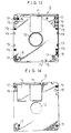
Also, the illustrated embodiment may be constructed in
such a manner as shown in Figs. 11 to 14. In Figs. 11 to 14, the
upper and lower plates 30 and 10 may be provided with welded
joints in place of the screwing bosses 32 and 13. Also, the
center frame 20 is formed on both upper and lower surfaces
thereof with recesses in a manner to be opposite to the welded
joints, so that the welded joints of the plates 30 and 10 are
engagedly fitted in the recesses to integrally assemble the disc
cartridge. Alternatively, the embodiment may be so constructed
that the screwing bosses 32 and 13 of the upper plate 30 and
lower plate 10 are arranged so as to be opposite to each other,
the center frame 20 is formed on both surfaces thereof with the
recesses 25 (Figs. 4 to 6) in which the screwing bosses 32 and 13
are engagedly fitted, and the upper plate 30 and/or lower plate
10 are provided with fit bosses 18 in a manner to be opposite to
each other. The fit bosses 18 thus arranged function to prevent
disassembling of the disc cartridge during assembling thereof and
ensure secure integrity of the disc cartridge after the
assembling.
The fit bosses 18 are formed with a vertical length or
height greater than a height of the screwing bosses 13 of the
lower plate 10. The center frame 20 is provided with blind holes
or through-holes 29 in which the fit bosses 18 are respectively
fitted. The fit bosses 18 of the lower plate 10 are fitted in
the holes 29 of the center frame 20 to ensure firm engagement
between the center frame 20 and the lower plate 10, when the disc
cartridge is assembled. Thus, the fit bosses 18 act as auxiliary
fixing means for promoting firm joining between both plates and
function to prevent warpage of the disc cartridge.
Instead, the upper plate 30 and lower plate 10 may be
securely joined to each other by means of tapping screws and the
fit bosses 18 of the plates 30 and 10 may be abutted on an end
surface thereof against to each other in through-holes of the
center frame 20. Then, the end surfaces of the fit bosses 18
abutted against to each other are welded together. Alternatively,
the end surfaces of the fit bosses 18 may be abutted against an
inner surface of the upper plate 30.
In the illustrated embodiment, the disc cartridge 1 and
therefore the center frame 20 may be formed with a substantially
square shape. The center frame 20 is formed at a portion thereof
in which parts for the disc cartridge or parts for the recording
and reproducing device are arranged or inserted into a reduced
thickness or with the holes. This may cause a possibility that
the center frame 20 fails to exhibit sufficient strength due to
unavoidable formation of any rib-like projection 27a such as the
corner of the center frame 20 at which the erasure preventing
plug insertion recess 27 is formed. In such a case, in order to
prevent breakage of the projection 27a, the corners of the upper
and lower plates 30 and 10 may be rounded at a radius curvature
smaller than that of the corner of the center frame 20 at which
the projection 27a is arranged. This permits the projection 27a
to be positioned inside the outer edge of the upper and lower
plates 30 and 10 when the disc cartridge is assembled.
In the illustrated embodiment, the thin-wall portions 23
of the center frame 20 are arranged on the lower surface and/or
upper surface of the center frame 20. When the upper and lower
plates 30 and 10 are made of a transparent or translucent resin
material, the thin-wall portions 23 may be formed from one of
upper and lower surfaces of the center frame 20, to thereby
prevent the thin-wall portions 23 from being in sight. Also,
this prevents warpage of the center frame 20. In the illustrated
embodiment, the thin-wall portions 23 are formed on the rear
surface of the center frame 20.
Also, in the illustrated embodiment, the upper plate 30
is formed on an upper or outer surface thereof with a shutter
slide area 33 and a label sticking area 34. Likewise, the lower
plate 10 is formed on a lower or outer surface thereof with a
shutter slide area 14. The shutter 51 of a substantially U-shape
in section is slidably fitted on the disc cartridge so as to be
slid on the shutter slide areas 33 and 14, to thereby selectively
cover the head insertion holes 31 and 11 and the drive shaft
insertion hole 12. The drive shaft insertion hole 12 is formed
at substantially the central portion of the lower plate 10, so
that the drive shaft of the recording and reproducing apparatus
is inserted into the drive shaft insertion hole 12, to thereby be
operatively connected to a clamping pin mounted on the disc-like
medium 40.
In the illustrated embodiment, the lower plate 10 is
provided with two such positioning bosses 18. Alternatively,
three or more such positioning bosses may be provided on the
lower plate 10. However, arrangement of only one such boss
sufficiently ensures positive fixing of the center frame 20 on
the lower plate 10. Also, two such fit bosses 18 are arranged on
each of the upper and lower plates in a manner to be diagonally
opposite to each other. Alternatively, one or more fit bosses
may be arranged on an outer edge of each of three sides of each
plate other than the side thereof on which the shutter 51 is
arranged.
Thus, it will be noted that the illustrated embodiment
permits an increase in rigidity of the center frame and prevents
generation of any sink mark on the center frame and any warpage
thereof, leading to an improvement in both dimensional accuracy
and appearance of the center frame and therefore the disc
cartridge and an improvement in assembling of the disc cartridge.
As described above, in the prior art, resin increased in
specific gravity has been used for providing the disc cartridge
with increased functionality and quality such as increased sound
reproducing characteristics, increased depth characteristics and
the like. As a result of a study by the inventors, it was found
that formation of a disc cartridge using only a composite resin
material increased in specific gravity permits the disc cartridge
to exhibit such characteristics when the specific gravity is 1.8
or more.
However, addition of a filler to molding resin to
increase specific gravity of the resin causes a thus-obtained
composite resin material which is a mixture of the resin with the
filler to be reduced in flowability or fluidity with an increase
in loadings of the filler. The prior art substantially failed to
consider that fluidity of the resin is closely relevant to a
volume of the filler to be added to the resin rather than a
weight of the filler. A careful study by the inventors revealed
that in order to ensure moldability of a molded article of a fine
structure, the content of filler in the composite resin material
is preferably 20 parts by volume or less based on 100 parts by
volume of the resin. The amount of filler above 20 parts by
volume causes a deterioration in dimensional accuracy and
appearance of a molded article and an increase in period of time
required for the molding, although it permits the molding under
elevated temperature and pressure conditions.
The disc cartridge which is a molded product reduced in
thickness is reduced in resistance to torsional stress as
compared with a cartridge for an audio tape or that for a video
tape. Thus, it is preferably constructed into a three-piece
structure so as to exhibit rigidity, as proposed in Japanese
Patent Application Laid-Open Publication No. 78478/1989 described
above.
In the illustrated embodiment, the disc cartridge is
constructed into a three-layer or three-piece structure including
the upper and lower plates 30 and 10 and the center frame 20,
wherein the upper and lower plates 30 and 10 are made of resin
conventionally used in the art and the center frame 20 is made of
a composite resin material containing both resin and a filler.
Such construction permits the center frame 20 to be constructed
into a simple structure free of any rib. Also, it ensures
satisfactory molding of the center frame 20 even when a filler
content is increased to a level as high as 50 parts by volume
based on 100 parts by volume of the resin.
Also, when the filler added to the resin for preparation
of the composite resin material is in the form of a powder, an
increase in volume of the filler causes the composite resin
material to be hard and brittle. The above-described
construction of the disc cartridge into the three-piece structure
permits the upper and lower plates 30 and 10 made of resin free
of any filler to interposedly protect the center frame 20 made of
the composite resin material described above, so that the
composite resin material used for molding the center frame 20 may
contain the filler in a large amount as compared with when a disc
cartridge is made of only the composite resin material.
It was found that when the disc cartridge is constructed
into the three-piece structure, specific gravity of the center
frame 20 of 2.5 or more leads to the above-described vibration-proofness
of the center frame 20 or disc cartridge. Although
specific gravity of the center frame 20 does not have any upper
limit, an upper limit of the specific gravity is about 7 in view
of loadings of the filler restricted by the above-described
moldability, commercially available materials for the center
frame and the like.
Also, it was found that when the center frame 20 has a
volume of 20% or more based on a combined volume of the upper and
lower plates 30 and 10 and the center frame 20, the above-described
vibration-proofness is improved. However, an increase
in volume of the center frame 20 to reduce a volume of the upper
and lower plates 30 and 10 causes protection of the center frame
20 by the upper and lower plates 30 and 10 to be deteriorated,
therefore, a volume of the center frame 20 is preferably 60% or
less based on the combined volume.
The prior art substantially fails to consider such
conditions and filler as described above. The filler such as
calcium carbonate, barium sulfate, lead sulfate, zinc oxide or
the like disclosed in the prior art completely fails to
concurrently meet all requirements on vibration-proofness,
productivity and reliability.
The filler suitable for practicing of the present
invention is a powder of an element or compound of 7 or more in
specific gravity. Also, the element or compound used as the
filler in the disc cartridge of the present invention is not
permitted to exhibit any radiation and toxicity because the disc
cartridge is used in daily living. Also, in order that the
filler exhibits increased reliability in operation in spite of a
long period of storage time, it preferably has good resistance to
corrosion. Materials for the filler which meet such conditions
and are commercially readily available include a stainless steel
powder and a tungsten powder.
The filler preferably has an average particle diameter of
from 1 to 20 µm and a maximum particle diameter of 50 µm or less.
An average particle diameter above 20 µm increases abrasion of a
molding die and that below 1 µm deteriorates dispersion of the
filler in the resin, leading to abrasion of the die and clogging
of gates.
Also, a surface treatment of the filler with a lubricant
or a silane or titanium coupling agent permits an improvement in
conformability of the filler to the resin, to thereby prevent a
deterioration in physical properties of the composite resin
material such as impact strength or the like due to addition of
the filler thereto and increase fluidity of the composite resin
material.
The resin used in the present invention is not limited to
any specific resin so long as it meets the requirements described
above. For example, resin which is conventionally used for
injection molding may be used in the present invention.
The invention will be understood more readily with
reference to the following example; however, the example is
intended to illustrate the invention and are not to be construed
to limit the scope of the invention.
Example
In the example, the disc cartridge of the present
invention for an MD or a magneto-optical disc was manufactured.
The disc cartridge was constructed in such a manner as shown in
Fig. 3.
Also, for comparison, a conventional disc cartridge
constructed in such a manner as shown in Fig. 1 was manufactured.
The conventional disc cartridge required to increase fluidity of
the resin in order to ensure satisfactory configurational and
dimensional accuracy, because it has such a complicated and fine
structure as shown in Fig. 1. In order to make the disc
cartridge of a composite resin material, it was required that the
composite resin compound contains the filler in an amount of 20
parts by volume based on 100 parts by volume of the resin.
The MD disc cartridges of the present invention and
comparative samples were made of materials shown in Table 1 under
conditions shown therein, wherein:
- Resin:
- polycarbonate (specific gravity = 1.2)
- Weight:
- 10 g
- Volume:
- 8.3 cm3
Center frame:
- Volume:
- shown in Table 1
- Resin:
- Polystyrene (PS) (specific gravity = 1.05)
Filler (F):
- W:
- Tungsten powder (specific gravity = 19.3)
- SUS:
- Stainless steel powder (specific gravity = 7.9)
- BS:
- Barium sulfate powder (specific gravity = 4.5)
- Cu:
- Copper powder (specific gravity = 9.0)
- Fe:
- Iron powder (specific gravity = 7.9)
- None:
- No filler
Filler loadings (FL): Parts by volume of filler based
on 100 parts by volume of resin Specific gravity of composite resin material (SG)
= (PS weight + F weight)/(PS volume + F volume) Moldability (M):
- O:
- Good
- ×:
- Bad
- Volume (V):
- cm3
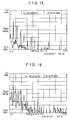
Plate volume (PV): cm3 Disc cartridge characteristics (DCC):
Vibration-proofness (VP): The cartridge fixed at one
end thereof was irradiated with sound waves of 60 Hz
from a speaker spaced by 1 cm from the cartridge, to
thereby measure vibration on a surface of the
cartridge opposite to a surface thereof facing the
speaker.
- ○:
- Good (Sample 3 of the present invention as shown in Fig. 15)
- Δ:
- Somewhat bad
- ×:
- Bad (Sample 22 for comparison as shown in Fig. 16)
Resin strength (RS): 1 m drop test
- O:
- No crack
- ×:
- Occurrence of crack
Corrosion resistance (CR): Spray test of 5% brine
according to JIS-Z2371 (48 hours)
- O:
- No rust
- ×:
- Occurrence of rust
Center frame volume proportion (CFV): %
| SN | CF | PV | DCC | CFV |
| | F | FL | SG | M | V | | VP | RS | CR |
| 1* | W | 5 | 1.9 | ○ | 2.3 | 8.3 | × | ○ | ○ | 28 |
| 2 | W | 8.5 | 2.5 | ○ | 2.3 | 8.3 | ○ | ○ | ○ | 28 |
| 3 | W | 10 | 2.7 | ○ | 2.3 | 8.3 | ○ | ○ | ○ | 28 |
| 4 | W | 15 | 3.4 | ○ | 2.3 | 8.3 | ○ | ○ | ○ | 28 |
| 5* | W | 10 | 2.7 | ○ | 1.5 | 8.3 | Δ | ○ | ○ | 18 |
| 6 | W | 10 | 2.7 | ○ | 1.7 | 8.3 | ○ | ○ | ○ | 20 |
| 7 | W | 10 | 2.7 | ○ | 2.0 | 8.3 | ○ | ○ | ○ | 24 |
| 8 | W | 10 | 2.7 | ○ | 2.6 | 8.3 | ○ | ○ | ○ | 31 |
| 9 | W | 10 | 2.7 | ○ | 4.0 | 8.3 | ○ | ○ | ○ | 48 |
| 10 | W | 40 | 6.3 | ○ | 2.3 | 8.3 | ○ | ○ | ○ | 28 |
| 11 | W | 50 | 7.1 | ○ | 2.3 | 8.3 | ○ | ○ | ○ | 28 |
| 12* | W | 55 | 7.5 | × | 2.3 | 8.3 | ○ | × | ○ | 28 |
| 13* | SUS | 25 | 2.4 | ○ | 2.3 | 8.3 | Δ | ○ | ○ | 28 |
| 14 | SUS | 30 | 2.6 | ○ | 2.3 | 8.3 | ○ | ○ | ○ | 28 |
| 15 | SUS | 45 | 3.2 | ○ | 2.3 | 8.3 | ○ | ○ | ○ | 28 |
| 16 | SUS | 50 | 3.3 | ○ | 2.3 | 8.3 | ○ | ○ | ○ | 28 |
| 17* | SUS | 55 | 3.5 | × | 2.3 | 8.3 | ○ | × | ○ | 28 |
| 18* | BS | 50 | 2.2 | ○ | 2.3 | 8.3 | Δ | ○ | ○ | 28 |
| 19* | BS | 55 | 2.3 | × | 2.3 | 8.3 | Δ | × | ○ | 28 |
| 20* | Fe | 45 | 3.2 | ○ | 2.3 | 8.3 | ○ | ○ | × | 28 |
| 21* | Cu | 45 | 3.5 | ○ | 2.3 | 8.3 | ○ | ○ | × | 28 |
| 22* | None | -- | 1.05 | ○ | --- | --- | × | ○ | ○ | -- |
While a preferred embodiment of the invention has been
described with a certain degree of particularity with reference
to the accompanying drawings, obvious modifications and
variations are possible in light of the above teachings. It is
therefore to be understood that within the scope of the appended
claims, the invention may be practiced otherwise than as
specifically described.