EP0872464B1 - Preparation of bioactive compounds by plasma synthesis - Google Patents
Preparation of bioactive compounds by plasma synthesis Download PDFInfo
- Publication number
- EP0872464B1 EP0872464B1 EP98302942A EP98302942A EP0872464B1 EP 0872464 B1 EP0872464 B1 EP 0872464B1 EP 98302942 A EP98302942 A EP 98302942A EP 98302942 A EP98302942 A EP 98302942A EP 0872464 B1 EP0872464 B1 EP 0872464B1
- Authority
- EP
- European Patent Office
- Prior art keywords
- plasma
- reactor
- reactants
- source
- plasma zone
- Prior art date
- Legal status (The legal status is an assumption and is not a legal conclusion. Google has not performed a legal analysis and makes no representation as to the accuracy of the status listed.)
- Expired - Lifetime
Links
- 150000001875 compounds Chemical class 0.000 title claims description 93
- 238000003786 synthesis reaction Methods 0.000 title description 40
- 230000015572 biosynthetic process Effects 0.000 title description 29
- 230000000975 bioactive effect Effects 0.000 title description 5
- 238000002360 preparation method Methods 0.000 title description 4
- 239000000376 reactant Substances 0.000 claims description 157
- 239000000203 mixture Substances 0.000 claims description 108
- 239000007787 solid Substances 0.000 claims description 38
- 238000000034 method Methods 0.000 claims description 34
- 150000002894 organic compounds Chemical class 0.000 claims description 27
- 239000007858 starting material Substances 0.000 claims description 25
- 230000000694 effects Effects 0.000 claims description 20
- 230000005764 inhibitory process Effects 0.000 claims description 14
- 102000004190 Enzymes Human genes 0.000 claims description 13
- 108090000790 Enzymes Proteins 0.000 claims description 13
- 230000027455 binding Effects 0.000 claims description 11
- 229920001222 biopolymer Polymers 0.000 claims description 10
- 230000004071 biological effect Effects 0.000 claims description 8
- 230000003993 interaction Effects 0.000 claims description 8
- 239000012528 membrane Substances 0.000 claims description 8
- 230000014509 gene expression Effects 0.000 claims description 6
- 230000002068 genetic effect Effects 0.000 claims description 6
- 230000012010 growth Effects 0.000 claims description 6
- 230000005855 radiation Effects 0.000 claims description 6
- 239000003990 capacitor Substances 0.000 claims description 5
- 230000005684 electric field Effects 0.000 claims description 5
- 230000005945 translocation Effects 0.000 claims description 5
- 239000003795 chemical substances by application Substances 0.000 claims description 4
- 239000008139 complexing agent Substances 0.000 claims description 4
- 230000010807 negative regulation of binding Effects 0.000 claims description 4
- 150000001720 carbohydrates Chemical class 0.000 claims description 3
- 108020004707 nucleic acids Proteins 0.000 claims description 3
- 102000039446 nucleic acids Human genes 0.000 claims description 3
- 150000007523 nucleic acids Chemical class 0.000 claims description 3
- 108090000765 processed proteins & peptides Proteins 0.000 claims description 3
- 102000004169 proteins and genes Human genes 0.000 claims description 3
- 108090000623 proteins and genes Proteins 0.000 claims description 3
- 238000010894 electron beam technology Methods 0.000 claims description 2
- 239000007921 spray Substances 0.000 claims description 2
- 239000012530 fluid Substances 0.000 claims 5
- LBDSXVIYZYSRII-IGMARMGPSA-N alpha-particle Chemical compound [4He+2] LBDSXVIYZYSRII-IGMARMGPSA-N 0.000 claims 1
- 210000002381 plasma Anatomy 0.000 description 129
- 239000000047 product Substances 0.000 description 95
- 238000006243 chemical reaction Methods 0.000 description 37
- 239000007789 gas Substances 0.000 description 37
- 230000005281 excited state Effects 0.000 description 36
- 238000012360 testing method Methods 0.000 description 34
- 241000894007 species Species 0.000 description 33
- 239000007788 liquid Substances 0.000 description 32
- 238000004128 high performance liquid chromatography Methods 0.000 description 22
- 238000012216 screening Methods 0.000 description 22
- 238000010992 reflux Methods 0.000 description 19
- 102000005962 receptors Human genes 0.000 description 18
- 108020003175 receptors Proteins 0.000 description 18
- 239000012043 crude product Substances 0.000 description 15
- 238000004519 manufacturing process Methods 0.000 description 15
- XKRFYHLGVUSROY-UHFFFAOYSA-N Argon Chemical compound [Ar] XKRFYHLGVUSROY-UHFFFAOYSA-N 0.000 description 14
- RTZKZFJDLAIYFH-UHFFFAOYSA-N Diethyl ether Chemical compound CCOCC RTZKZFJDLAIYFH-UHFFFAOYSA-N 0.000 description 13
- 239000000126 substance Substances 0.000 description 13
- WEVYAHXRMPXWCK-UHFFFAOYSA-N Acetonitrile Chemical compound CC#N WEVYAHXRMPXWCK-UHFFFAOYSA-N 0.000 description 12
- 230000035484 reaction time Effects 0.000 description 12
- XLYOFNOQVPJJNP-UHFFFAOYSA-N water Substances O XLYOFNOQVPJJNP-UHFFFAOYSA-N 0.000 description 12
- 229910001868 water Inorganic materials 0.000 description 11
- VVJKKWFAADXIJK-UHFFFAOYSA-N Allylamine Chemical compound NCC=C VVJKKWFAADXIJK-UHFFFAOYSA-N 0.000 description 10
- IRMPFYJSHJGOPE-UHFFFAOYSA-N olivetol Chemical compound CCCCCC1=CC(O)=CC(O)=C1 IRMPFYJSHJGOPE-UHFFFAOYSA-N 0.000 description 10
- 230000008569 process Effects 0.000 description 10
- GHMLBKRAJCXXBS-UHFFFAOYSA-N resorcinol Chemical compound OC1=CC=CC(O)=C1 GHMLBKRAJCXXBS-UHFFFAOYSA-N 0.000 description 10
- -1 plant extracts Natural products 0.000 description 9
- 238000000825 ultraviolet detection Methods 0.000 description 9
- VLKZOEOYAKHREP-UHFFFAOYSA-N n-Hexane Chemical compound CCCCCC VLKZOEOYAKHREP-UHFFFAOYSA-N 0.000 description 8
- 239000000523 sample Substances 0.000 description 8
- 229910052786 argon Inorganic materials 0.000 description 7
- 210000004027 cell Anatomy 0.000 description 7
- UWYZHKAOTLEWKK-UHFFFAOYSA-N 1,2,3,4-tetrahydroisoquinoline Chemical compound C1=CC=C2CNCCC2=C1 UWYZHKAOTLEWKK-UHFFFAOYSA-N 0.000 description 6
- ANOUKFYBOAKOIR-UHFFFAOYSA-N 3,4-dimethoxyphenylethylamine Chemical compound COC1=CC=C(CCN)C=C1OC ANOUKFYBOAKOIR-UHFFFAOYSA-N 0.000 description 6
- LUMNWCHHXDUKFI-UHFFFAOYSA-N 5-bicyclo[2.2.1]hept-2-enylmethanol Chemical compound C1C2C(CO)CC1C=C2 LUMNWCHHXDUKFI-UHFFFAOYSA-N 0.000 description 6
- CSCPPACGZOOCGX-UHFFFAOYSA-N Acetone Chemical compound CC(C)=O CSCPPACGZOOCGX-UHFFFAOYSA-N 0.000 description 6
- IJGRMHOSHXDMSA-UHFFFAOYSA-N Atomic nitrogen Chemical compound N#N IJGRMHOSHXDMSA-UHFFFAOYSA-N 0.000 description 6
- QGJOPFRUJISHPQ-UHFFFAOYSA-N Carbon disulfide Chemical compound S=C=S QGJOPFRUJISHPQ-UHFFFAOYSA-N 0.000 description 6
- YXFVVABEGXRONW-UHFFFAOYSA-N Toluene Chemical compound CC1=CC=CC=C1 YXFVVABEGXRONW-UHFFFAOYSA-N 0.000 description 6
- 238000001816 cooling Methods 0.000 description 6
- BGTOWKSIORTVQH-UHFFFAOYSA-N cyclopentanone Chemical compound O=C1CCCC1 BGTOWKSIORTVQH-UHFFFAOYSA-N 0.000 description 6
- 238000004949 mass spectrometry Methods 0.000 description 6
- QGZKDVFQNNGYKY-UHFFFAOYSA-N Ammonia Chemical compound N QGZKDVFQNNGYKY-UHFFFAOYSA-N 0.000 description 5
- 238000013459 approach Methods 0.000 description 5
- 238000011161 development Methods 0.000 description 5
- 238000007876 drug discovery Methods 0.000 description 5
- 230000005283 ground state Effects 0.000 description 5
- 238000010438 heat treatment Methods 0.000 description 5
- 238000002329 infrared spectrum Methods 0.000 description 5
- 230000002459 sustained effect Effects 0.000 description 5
- WYURNTSHIVDZCO-UHFFFAOYSA-N Tetrahydrofuran Chemical compound C1CCOC1 WYURNTSHIVDZCO-UHFFFAOYSA-N 0.000 description 4
- 150000001336 alkenes Chemical group 0.000 description 4
- 125000004429 atom Chemical group 0.000 description 4
- 239000003153 chemical reaction reagent Substances 0.000 description 4
- 238000013461 design Methods 0.000 description 4
- 238000004821 distillation Methods 0.000 description 4
- 239000011521 glass Substances 0.000 description 4
- 239000008187 granular material Substances 0.000 description 4
- 238000013537 high throughput screening Methods 0.000 description 4
- 125000002887 hydroxy group Chemical group [H]O* 0.000 description 4
- 150000002576 ketones Chemical class 0.000 description 4
- 239000000463 material Substances 0.000 description 4
- 125000002496 methyl group Chemical group [H]C([H])([H])* 0.000 description 4
- 239000002002 slurry Substances 0.000 description 4
- ZWEHNKRNPOVVGH-UHFFFAOYSA-N 2-Butanone Chemical compound CCC(C)=O ZWEHNKRNPOVVGH-UHFFFAOYSA-N 0.000 description 3
- QTBSBXVTEAMEQO-UHFFFAOYSA-N Acetic acid Chemical compound CC(O)=O QTBSBXVTEAMEQO-UHFFFAOYSA-N 0.000 description 3
- UHOVQNZJYSORNB-UHFFFAOYSA-N Benzene Chemical compound C1=CC=CC=C1 UHOVQNZJYSORNB-UHFFFAOYSA-N 0.000 description 3
- CURLTUGMZLYLDI-UHFFFAOYSA-N Carbon dioxide Chemical compound O=C=O CURLTUGMZLYLDI-UHFFFAOYSA-N 0.000 description 3
- YMWUJEATGCHHMB-UHFFFAOYSA-N Dichloromethane Chemical compound ClCCl YMWUJEATGCHHMB-UHFFFAOYSA-N 0.000 description 3
- LFQSCWFLJHTTHZ-UHFFFAOYSA-N Ethanol Chemical compound CCO LFQSCWFLJHTTHZ-UHFFFAOYSA-N 0.000 description 3
- HSFWRNGVRCDJHI-UHFFFAOYSA-N alpha-acetylene Natural products C#C HSFWRNGVRCDJHI-UHFFFAOYSA-N 0.000 description 3
- QVGXLLKOCUKJST-UHFFFAOYSA-N atomic oxygen Chemical compound [O] QVGXLLKOCUKJST-UHFFFAOYSA-N 0.000 description 3
- 229960004132 diethyl ether Drugs 0.000 description 3
- 125000002534 ethynyl group Chemical group [H]C#C* 0.000 description 3
- 239000012634 fragment Substances 0.000 description 3
- 125000000524 functional group Chemical group 0.000 description 3
- 238000004817 gas chromatography Methods 0.000 description 3
- 239000001307 helium Substances 0.000 description 3
- 229910052734 helium Inorganic materials 0.000 description 3
- SWQJXJOGLNCZEY-UHFFFAOYSA-N helium atom Chemical compound [He] SWQJXJOGLNCZEY-UHFFFAOYSA-N 0.000 description 3
- YAMHXTCMCPHKLN-UHFFFAOYSA-N imidazolidin-2-one Chemical compound O=C1NCCN1 YAMHXTCMCPHKLN-UHFFFAOYSA-N 0.000 description 3
- 239000011261 inert gas Substances 0.000 description 3
- 230000005865 ionizing radiation Effects 0.000 description 3
- 239000012263 liquid product Substances 0.000 description 3
- KKFHAJHLJHVUDM-UHFFFAOYSA-N n-vinylcarbazole Chemical compound C1=CC=C2N(C=C)C3=CC=CC=C3C2=C1 KKFHAJHLJHVUDM-UHFFFAOYSA-N 0.000 description 3
- 229930014626 natural product Natural products 0.000 description 3
- 229910052757 nitrogen Inorganic materials 0.000 description 3
- JRZJOMJEPLMPRA-UHFFFAOYSA-N olefin Natural products CCCCCCCC=C JRZJOMJEPLMPRA-UHFFFAOYSA-N 0.000 description 3
- 239000001301 oxygen Substances 0.000 description 3
- 229910052760 oxygen Inorganic materials 0.000 description 3
- 150000003254 radicals Chemical class 0.000 description 3
- 239000012265 solid product Substances 0.000 description 3
- 239000002904 solvent Substances 0.000 description 3
- 238000001228 spectrum Methods 0.000 description 3
- TXEYQDLBPFQVAA-UHFFFAOYSA-N tetrafluoromethane Chemical compound FC(F)(F)F TXEYQDLBPFQVAA-UHFFFAOYSA-N 0.000 description 3
- 239000012808 vapor phase Substances 0.000 description 3
- RFFLAFLAYFXFSW-UHFFFAOYSA-N 1,2-dichlorobenzene Chemical compound ClC1=CC=CC=C1Cl RFFLAFLAYFXFSW-UHFFFAOYSA-N 0.000 description 2
- HZAXFHJVJLSVMW-UHFFFAOYSA-N 2-Aminoethan-1-ol Chemical compound NCCO HZAXFHJVJLSVMW-UHFFFAOYSA-N 0.000 description 2
- 229910001369 Brass Inorganic materials 0.000 description 2
- 241000218236 Cannabis Species 0.000 description 2
- RYGMFSIKBFXOCR-UHFFFAOYSA-N Copper Chemical compound [Cu] RYGMFSIKBFXOCR-UHFFFAOYSA-N 0.000 description 2
- HPEUJPJOZXNMSJ-UHFFFAOYSA-N Methyl stearate Chemical compound CCCCCCCCCCCCCCCCCC(=O)OC HPEUJPJOZXNMSJ-UHFFFAOYSA-N 0.000 description 2
- 238000005481 NMR spectroscopy Methods 0.000 description 2
- ISWSIDIOOBJBQZ-UHFFFAOYSA-N Phenol Chemical compound OC1=CC=CC=C1 ISWSIDIOOBJBQZ-UHFFFAOYSA-N 0.000 description 2
- ATUOYWHBWRKTHZ-UHFFFAOYSA-N Propane Chemical compound CCC ATUOYWHBWRKTHZ-UHFFFAOYSA-N 0.000 description 2
- JUJWROOIHBZHMG-UHFFFAOYSA-N Pyridine Chemical compound C1=CC=NC=C1 JUJWROOIHBZHMG-UHFFFAOYSA-N 0.000 description 2
- 229910000831 Steel Inorganic materials 0.000 description 2
- 230000009471 action Effects 0.000 description 2
- 150000001345 alkine derivatives Chemical class 0.000 description 2
- 229910052782 aluminium Inorganic materials 0.000 description 2
- XAGFODPZIPBFFR-UHFFFAOYSA-N aluminium Chemical compound [Al] XAGFODPZIPBFFR-UHFFFAOYSA-N 0.000 description 2
- 150000001408 amides Chemical class 0.000 description 2
- 150000001412 amines Chemical class 0.000 description 2
- 125000003277 amino group Chemical group 0.000 description 2
- 229910021529 ammonia Inorganic materials 0.000 description 2
- 125000003118 aryl group Chemical group 0.000 description 2
- 230000008901 benefit Effects 0.000 description 2
- 239000010951 brass Substances 0.000 description 2
- 125000002915 carbonyl group Chemical group [*:2]C([*:1])=O 0.000 description 2
- 230000005495 cold plasma Effects 0.000 description 2
- 239000002826 coolant Substances 0.000 description 2
- 229910052802 copper Inorganic materials 0.000 description 2
- 239000010949 copper Substances 0.000 description 2
- JHIVVAPYMSGYDF-UHFFFAOYSA-N cyclohexanone Chemical compound O=C1CCCCC1 JHIVVAPYMSGYDF-UHFFFAOYSA-N 0.000 description 2
- RWRIWBAIICGTTQ-UHFFFAOYSA-N difluoromethane Chemical compound FCF RWRIWBAIICGTTQ-UHFFFAOYSA-N 0.000 description 2
- 238000006911 enzymatic reaction Methods 0.000 description 2
- 150000002148 esters Chemical class 0.000 description 2
- 125000001153 fluoro group Chemical group F* 0.000 description 2
- 238000002290 gas chromatography-mass spectrometry Methods 0.000 description 2
- 239000000122 growth hormone Substances 0.000 description 2
- 239000001257 hydrogen Substances 0.000 description 2
- 229910052739 hydrogen Inorganic materials 0.000 description 2
- 150000002484 inorganic compounds Chemical class 0.000 description 2
- 229910010272 inorganic material Inorganic materials 0.000 description 2
- 238000002955 isolation Methods 0.000 description 2
- 239000003446 ligand Substances 0.000 description 2
- 238000001819 mass spectrum Methods 0.000 description 2
- 238000002844 melting Methods 0.000 description 2
- 125000000325 methylidene group Chemical group [H]C([H])=* 0.000 description 2
- 230000007935 neutral effect Effects 0.000 description 2
- 239000002245 particle Substances 0.000 description 2
- QMMOXUPEWRXHJS-UHFFFAOYSA-N pentene-2 Natural products CCC=CC QMMOXUPEWRXHJS-UHFFFAOYSA-N 0.000 description 2
- 239000012071 phase Substances 0.000 description 2
- YNPNZTXNASCQKK-UHFFFAOYSA-N phenanthrene Chemical compound C1=CC=C2C3=CC=CC=C3C=CC2=C1 YNPNZTXNASCQKK-UHFFFAOYSA-N 0.000 description 2
- 230000008635 plant growth Effects 0.000 description 2
- 239000012264 purified product Substances 0.000 description 2
- 238000010791 quenching Methods 0.000 description 2
- 239000012262 resinous product Substances 0.000 description 2
- 238000005507 spraying Methods 0.000 description 2
- 239000010959 steel Substances 0.000 description 2
- 238000003756 stirring Methods 0.000 description 2
- YLQBMQCUIZJEEH-UHFFFAOYSA-N tetrahydrofuran Natural products C=1C=COC=1 YLQBMQCUIZJEEH-UHFFFAOYSA-N 0.000 description 2
- CRLBBOBKCLYCJK-UHFFFAOYSA-N (2,3-dimethoxyphenyl)methanol Chemical compound COC1=CC=CC(CO)=C1OC CRLBBOBKCLYCJK-UHFFFAOYSA-N 0.000 description 1
- JNTPTNNCGDAGEJ-UHFFFAOYSA-N 6-chlorohexan-1-ol Chemical compound OCCCCCCCl JNTPTNNCGDAGEJ-UHFFFAOYSA-N 0.000 description 1
- 241000894006 Bacteria Species 0.000 description 1
- DKPFZGUDAPQIHT-UHFFFAOYSA-N Butyl acetate Natural products CCCCOC(C)=O DKPFZGUDAPQIHT-UHFFFAOYSA-N 0.000 description 1
- UGFAIRIUMAVXCW-UHFFFAOYSA-N Carbon monoxide Chemical compound [O+]#[C-] UGFAIRIUMAVXCW-UHFFFAOYSA-N 0.000 description 1
- VOPWNXZWBYDODV-UHFFFAOYSA-N Chlorodifluoromethane Chemical compound FC(F)Cl VOPWNXZWBYDODV-UHFFFAOYSA-N 0.000 description 1
- 101100285402 Danio rerio eng1a gene Proteins 0.000 description 1
- 241000196324 Embryophyta Species 0.000 description 1
- XPDWGBQVDMORPB-UHFFFAOYSA-N Fluoroform Chemical group FC(F)F XPDWGBQVDMORPB-UHFFFAOYSA-N 0.000 description 1
- UFHFLCQGNIYNRP-UHFFFAOYSA-N Hydrogen Chemical compound [H][H] UFHFLCQGNIYNRP-UHFFFAOYSA-N 0.000 description 1
- 238000004566 IR spectroscopy Methods 0.000 description 1
- LSDPWZHWYPCBBB-UHFFFAOYSA-N Methanethiol Chemical compound SC LSDPWZHWYPCBBB-UHFFFAOYSA-N 0.000 description 1
- 238000002835 absorbance Methods 0.000 description 1
- 238000010521 absorption reaction Methods 0.000 description 1
- IKHGUXGNUITLKF-XPULMUKRSA-N acetaldehyde Chemical compound [14CH]([14CH3])=O IKHGUXGNUITLKF-XPULMUKRSA-N 0.000 description 1
- 230000004913 activation Effects 0.000 description 1
- 150000001299 aldehydes Chemical class 0.000 description 1
- 125000003046 allene group Chemical group 0.000 description 1
- 150000001361 allenes Chemical class 0.000 description 1
- 238000004458 analytical method Methods 0.000 description 1
- 239000003242 anti bacterial agent Substances 0.000 description 1
- 229940088710 antibiotic agent Drugs 0.000 description 1
- 239000012472 biological sample Substances 0.000 description 1
- 239000001569 carbon dioxide Substances 0.000 description 1
- 229910002092 carbon dioxide Inorganic materials 0.000 description 1
- 235000011089 carbon dioxide Nutrition 0.000 description 1
- 229910002091 carbon monoxide Inorganic materials 0.000 description 1
- 150000001793 charged compounds Chemical class 0.000 description 1
- 125000003636 chemical group Chemical group 0.000 description 1
- 238000004587 chromatography analysis Methods 0.000 description 1
- 238000004440 column chromatography Methods 0.000 description 1
- 230000009137 competitive binding Effects 0.000 description 1
- 239000004020 conductor Substances 0.000 description 1
- 239000012809 cooling fluid Substances 0.000 description 1
- 239000000498 cooling water Substances 0.000 description 1
- 150000001923 cyclic compounds Chemical class 0.000 description 1
- 125000004122 cyclic group Chemical group 0.000 description 1
- 238000000354 decomposition reaction Methods 0.000 description 1
- 238000006073 displacement reaction Methods 0.000 description 1
- 238000004090 dissolution Methods 0.000 description 1
- 125000002228 disulfide group Chemical group 0.000 description 1
- 238000009510 drug design Methods 0.000 description 1
- 238000007877 drug screening Methods 0.000 description 1
- 238000005485 electric heating Methods 0.000 description 1
- 238000001962 electrophoresis Methods 0.000 description 1
- 238000000921 elemental analysis Methods 0.000 description 1
- 238000005516 engineering process Methods 0.000 description 1
- 150000002118 epoxides Chemical class 0.000 description 1
- CAMHHLOGFDZBBG-UHFFFAOYSA-N epoxidized methyl oleate Natural products CCCCCCCCC1OC1CCCCCCCC(=O)OC CAMHHLOGFDZBBG-UHFFFAOYSA-N 0.000 description 1
- 239000000284 extract Substances 0.000 description 1
- 238000000605 extraction Methods 0.000 description 1
- 239000007888 film coating Substances 0.000 description 1
- 238000009501 film coating Methods 0.000 description 1
- 238000001914 filtration Methods 0.000 description 1
- 238000001640 fractional crystallisation Methods 0.000 description 1
- 238000005194 fractionation Methods 0.000 description 1
- 229910052736 halogen Inorganic materials 0.000 description 1
- 150000002367 halogens Chemical class 0.000 description 1
- 230000002363 herbicidal effect Effects 0.000 description 1
- 239000004009 herbicide Substances 0.000 description 1
- 125000005842 heteroatom Chemical group 0.000 description 1
- FUZZWVXGSFPDMH-UHFFFAOYSA-M hexanoate Chemical compound CCCCCC([O-])=O FUZZWVXGSFPDMH-UHFFFAOYSA-M 0.000 description 1
- 229920006158 high molecular weight polymer Polymers 0.000 description 1
- 125000004435 hydrogen atom Chemical class [H]* 0.000 description 1
- 238000007654 immersion Methods 0.000 description 1
- 239000002198 insoluble material Substances 0.000 description 1
- 150000002500 ions Chemical class 0.000 description 1
- 238000011005 laboratory method Methods 0.000 description 1
- 238000004811 liquid chromatography Methods 0.000 description 1
- 239000000155 melt Substances 0.000 description 1
- 230000008018 melting Effects 0.000 description 1
- 229910052751 metal Inorganic materials 0.000 description 1
- 239000002184 metal Substances 0.000 description 1
- 238000002156 mixing Methods 0.000 description 1
- NBVXSUQYWXRMNV-UHFFFAOYSA-N monofluoromethane Natural products FC NBVXSUQYWXRMNV-UHFFFAOYSA-N 0.000 description 1
- 230000017066 negative regulation of growth Effects 0.000 description 1
- 125000002560 nitrile group Chemical group 0.000 description 1
- 239000000575 pesticide Substances 0.000 description 1
- 239000000419 plant extract Substances 0.000 description 1
- 238000009832 plasma treatment Methods 0.000 description 1
- 229920000642 polymer Polymers 0.000 description 1
- 230000003389 potentiating effect Effects 0.000 description 1
- 239000001294 propane Substances 0.000 description 1
- UMJSCPRVCHMLSP-UHFFFAOYSA-N pyridine Natural products COC1=CC=CN=C1 UMJSCPRVCHMLSP-UHFFFAOYSA-N 0.000 description 1
- 230000000171 quenching effect Effects 0.000 description 1
- JWVCLYRUEFBMGU-UHFFFAOYSA-N quinazoline Chemical compound N1=CN=CC2=CC=CC=C21 JWVCLYRUEFBMGU-UHFFFAOYSA-N 0.000 description 1
- 238000009790 rate-determining step (RDS) Methods 0.000 description 1
- 230000006798 recombination Effects 0.000 description 1
- 238000005215 recombination Methods 0.000 description 1
- 238000011084 recovery Methods 0.000 description 1
- 238000000926 separation method Methods 0.000 description 1
- 238000001542 size-exclusion chromatography Methods 0.000 description 1
- 238000000638 solvent extraction Methods 0.000 description 1
- PXQLVRUNWNTZOS-UHFFFAOYSA-N sulfanyl Chemical compound [SH] PXQLVRUNWNTZOS-UHFFFAOYSA-N 0.000 description 1
- 230000002194 synthesizing effect Effects 0.000 description 1
- 238000005979 thermal decomposition reaction Methods 0.000 description 1
- 150000003573 thiols Chemical class 0.000 description 1
- 231100000041 toxicology testing Toxicity 0.000 description 1
- 238000012546 transfer Methods 0.000 description 1
- JSPLKZUTYZBBKA-UHFFFAOYSA-N trioxidane Chemical compound OOO JSPLKZUTYZBBKA-UHFFFAOYSA-N 0.000 description 1
Images







Classifications
-
- C—CHEMISTRY; METALLURGY
- C40—COMBINATORIAL TECHNOLOGY
- C40B—COMBINATORIAL CHEMISTRY; LIBRARIES, e.g. CHEMICAL LIBRARIES
- C40B40/00—Libraries per se, e.g. arrays, mixtures
- C40B40/04—Libraries containing only organic compounds
-
- B—PERFORMING OPERATIONS; TRANSPORTING
- B01—PHYSICAL OR CHEMICAL PROCESSES OR APPARATUS IN GENERAL
- B01J—CHEMICAL OR PHYSICAL PROCESSES, e.g. CATALYSIS OR COLLOID CHEMISTRY; THEIR RELEVANT APPARATUS
- B01J12/00—Chemical processes in general for reacting gaseous media with gaseous media; Apparatus specially adapted therefor
- B01J12/002—Chemical processes in general for reacting gaseous media with gaseous media; Apparatus specially adapted therefor carried out in the plasma state
-
- B—PERFORMING OPERATIONS; TRANSPORTING
- B01—PHYSICAL OR CHEMICAL PROCESSES OR APPARATUS IN GENERAL
- B01J—CHEMICAL OR PHYSICAL PROCESSES, e.g. CATALYSIS OR COLLOID CHEMISTRY; THEIR RELEVANT APPARATUS
- B01J19/00—Chemical, physical or physico-chemical processes in general; Their relevant apparatus
- B01J19/0046—Sequential or parallel reactions, e.g. for the synthesis of polypeptides or polynucleotides; Apparatus and devices for combinatorial chemistry or for making molecular arrays
-
- B—PERFORMING OPERATIONS; TRANSPORTING
- B01—PHYSICAL OR CHEMICAL PROCESSES OR APPARATUS IN GENERAL
- B01J—CHEMICAL OR PHYSICAL PROCESSES, e.g. CATALYSIS OR COLLOID CHEMISTRY; THEIR RELEVANT APPARATUS
- B01J19/00—Chemical, physical or physico-chemical processes in general; Their relevant apparatus
- B01J19/08—Processes employing the direct application of electric or wave energy, or particle radiation; Apparatus therefor
- B01J19/087—Processes employing the direct application of electric or wave energy, or particle radiation; Apparatus therefor employing electric or magnetic energy
- B01J19/088—Processes employing the direct application of electric or wave energy, or particle radiation; Apparatus therefor employing electric or magnetic energy giving rise to electric discharges
-
- B—PERFORMING OPERATIONS; TRANSPORTING
- B01—PHYSICAL OR CHEMICAL PROCESSES OR APPARATUS IN GENERAL
- B01J—CHEMICAL OR PHYSICAL PROCESSES, e.g. CATALYSIS OR COLLOID CHEMISTRY; THEIR RELEVANT APPARATUS
- B01J8/00—Chemical or physical processes in general, conducted in the presence of fluids and solid particles; Apparatus for such processes
- B01J8/02—Chemical or physical processes in general, conducted in the presence of fluids and solid particles; Apparatus for such processes with stationary particles, e.g. in fixed beds
- B01J8/0242—Chemical or physical processes in general, conducted in the presence of fluids and solid particles; Apparatus for such processes with stationary particles, e.g. in fixed beds the fluid flow within the bed being predominantly vertical
- B01J8/025—Chemical or physical processes in general, conducted in the presence of fluids and solid particles; Apparatus for such processes with stationary particles, e.g. in fixed beds the fluid flow within the bed being predominantly vertical in a cylindrical shaped bed
-
- C—CHEMISTRY; METALLURGY
- C07—ORGANIC CHEMISTRY
- C07B—GENERAL METHODS OF ORGANIC CHEMISTRY; APPARATUS THEREFOR
- C07B61/00—Other general methods
-
- C—CHEMISTRY; METALLURGY
- C40—COMBINATORIAL TECHNOLOGY
- C40B—COMBINATORIAL CHEMISTRY; LIBRARIES, e.g. CHEMICAL LIBRARIES
- C40B50/00—Methods of creating libraries, e.g. combinatorial synthesis
- C40B50/08—Liquid phase synthesis, i.e. wherein all library building blocks are in liquid phase or in solution during library creation; Particular methods of cleavage from the liquid support
-
- B—PERFORMING OPERATIONS; TRANSPORTING
- B01—PHYSICAL OR CHEMICAL PROCESSES OR APPARATUS IN GENERAL
- B01J—CHEMICAL OR PHYSICAL PROCESSES, e.g. CATALYSIS OR COLLOID CHEMISTRY; THEIR RELEVANT APPARATUS
- B01J2219/00—Chemical, physical or physico-chemical processes in general; Their relevant apparatus
- B01J2219/00049—Controlling or regulating processes
- B01J2219/00051—Controlling the temperature
- B01J2219/00132—Controlling the temperature using electric heating or cooling elements
- B01J2219/00135—Electric resistance heaters
-
- B—PERFORMING OPERATIONS; TRANSPORTING
- B01—PHYSICAL OR CHEMICAL PROCESSES OR APPARATUS IN GENERAL
- B01J—CHEMICAL OR PHYSICAL PROCESSES, e.g. CATALYSIS OR COLLOID CHEMISTRY; THEIR RELEVANT APPARATUS
- B01J2219/00—Chemical, physical or physico-chemical processes in general; Their relevant apparatus
- B01J2219/00274—Sequential or parallel reactions; Apparatus and devices for combinatorial chemistry or for making arrays; Chemical library technology
- B01J2219/00277—Apparatus
- B01J2219/00279—Features relating to reactor vessels
- B01J2219/00281—Individual reactor vessels
- B01J2219/00286—Reactor vessels with top and bottom openings
-
- B—PERFORMING OPERATIONS; TRANSPORTING
- B01—PHYSICAL OR CHEMICAL PROCESSES OR APPARATUS IN GENERAL
- B01J—CHEMICAL OR PHYSICAL PROCESSES, e.g. CATALYSIS OR COLLOID CHEMISTRY; THEIR RELEVANT APPARATUS
- B01J2219/00—Chemical, physical or physico-chemical processes in general; Their relevant apparatus
- B01J2219/00274—Sequential or parallel reactions; Apparatus and devices for combinatorial chemistry or for making arrays; Chemical library technology
- B01J2219/00583—Features relative to the processes being carried out
- B01J2219/00599—Solution-phase processes
-
- B—PERFORMING OPERATIONS; TRANSPORTING
- B01—PHYSICAL OR CHEMICAL PROCESSES OR APPARATUS IN GENERAL
- B01J—CHEMICAL OR PHYSICAL PROCESSES, e.g. CATALYSIS OR COLLOID CHEMISTRY; THEIR RELEVANT APPARATUS
- B01J2219/00—Chemical, physical or physico-chemical processes in general; Their relevant apparatus
- B01J2219/00274—Sequential or parallel reactions; Apparatus and devices for combinatorial chemistry or for making arrays; Chemical library technology
- B01J2219/00718—Type of compounds synthesised
- B01J2219/0072—Organic compounds
-
- B—PERFORMING OPERATIONS; TRANSPORTING
- B01—PHYSICAL OR CHEMICAL PROCESSES OR APPARATUS IN GENERAL
- B01J—CHEMICAL OR PHYSICAL PROCESSES, e.g. CATALYSIS OR COLLOID CHEMISTRY; THEIR RELEVANT APPARATUS
- B01J2219/00—Chemical, physical or physico-chemical processes in general; Their relevant apparatus
- B01J2219/08—Processes employing the direct application of electric or wave energy, or particle radiation; Apparatus therefor
- B01J2219/0803—Processes employing the direct application of electric or wave energy, or particle radiation; Apparatus therefor employing electric or magnetic energy
- B01J2219/0805—Processes employing the direct application of electric or wave energy, or particle radiation; Apparatus therefor employing electric or magnetic energy giving rise to electric discharges
- B01J2219/0807—Processes employing the direct application of electric or wave energy, or particle radiation; Apparatus therefor employing electric or magnetic energy giving rise to electric discharges involving electrodes
- B01J2219/0809—Processes employing the direct application of electric or wave energy, or particle radiation; Apparatus therefor employing electric or magnetic energy giving rise to electric discharges involving electrodes employing two or more electrodes
-
- B—PERFORMING OPERATIONS; TRANSPORTING
- B01—PHYSICAL OR CHEMICAL PROCESSES OR APPARATUS IN GENERAL
- B01J—CHEMICAL OR PHYSICAL PROCESSES, e.g. CATALYSIS OR COLLOID CHEMISTRY; THEIR RELEVANT APPARATUS
- B01J2219/00—Chemical, physical or physico-chemical processes in general; Their relevant apparatus
- B01J2219/08—Processes employing the direct application of electric or wave energy, or particle radiation; Apparatus therefor
- B01J2219/0873—Materials to be treated
- B01J2219/0881—Two or more materials
- B01J2219/0886—Gas-solid
-
- B—PERFORMING OPERATIONS; TRANSPORTING
- B01—PHYSICAL OR CHEMICAL PROCESSES OR APPARATUS IN GENERAL
- B01J—CHEMICAL OR PHYSICAL PROCESSES, e.g. CATALYSIS OR COLLOID CHEMISTRY; THEIR RELEVANT APPARATUS
- B01J2219/00—Chemical, physical or physico-chemical processes in general; Their relevant apparatus
- B01J2219/19—Details relating to the geometry of the reactor
- B01J2219/194—Details relating to the geometry of the reactor round
- B01J2219/1941—Details relating to the geometry of the reactor round circular or disk-shaped
- B01J2219/1942—Details relating to the geometry of the reactor round circular or disk-shaped spherical
-
- G—PHYSICS
- G01—MEASURING; TESTING
- G01N—INVESTIGATING OR ANALYSING MATERIALS BY DETERMINING THEIR CHEMICAL OR PHYSICAL PROPERTIES
- G01N2500/00—Screening for compounds of potential therapeutic value
-
- Y—GENERAL TAGGING OF NEW TECHNOLOGICAL DEVELOPMENTS; GENERAL TAGGING OF CROSS-SECTIONAL TECHNOLOGIES SPANNING OVER SEVERAL SECTIONS OF THE IPC; TECHNICAL SUBJECTS COVERED BY FORMER USPC CROSS-REFERENCE ART COLLECTIONS [XRACs] AND DIGESTS
- Y10—TECHNICAL SUBJECTS COVERED BY FORMER USPC
- Y10S—TECHNICAL SUBJECTS COVERED BY FORMER USPC CROSS-REFERENCE ART COLLECTIONS [XRACs] AND DIGESTS
- Y10S422/00—Chemical apparatus and process disinfecting, deodorizing, preserving, or sterilizing
- Y10S422/907—Corona or glow discharge means
Definitions
- the traditional sources of compounds for screening such as natural products or the products of rational drug design, cannot furnish the numbers of compounds needed to meet this demand, while combinatorial synthesis produces large numbers of compounds but they have insufficient diversity of structures.
- the present invention is directed at the development of a new method to synthesize and screen large numbers of structurally diverse compounds.
- Plasma glow discharges have been used to prepare specific compounds from vaporized organic reactants. See, for example, Cvetanovic, 1 Adv. Photochem. 115 (1963) wherein the production of an aldhyde, two epoxides and two ketones from a mixture of 2-pentene and oxygen was reported. See also, Suhr, 11 Angew. Chem. Int. Ed. Eng1. 781 (1972), which discloses the limited production of several cyclic compounds from acetylene; however, unless the reaction is rapidly quenched, the primary products are polymers. Ibid.
- the primary focus of prior attempts to synthesize new products by exposure of one or more reactants to a glow discharge has been to maximize conversion and yield of a single desired product which, due to the inherent difficulty in controlling plasma discharge reactions, has been largely unsuccessful.
- the present invention is based upon the recognition that such inherent uncontrollability can be used to advantage in preparing a multitude of organic compounds containing diverse chemical structures and functional groups, and that the resultant product mix, when coupled with bioactivity screening, can ultimately lead to the production of significant numbers of useful compounds.
- the present invention comprises a novel process for synthesizing and identifying compounds with desirable bioactivity. Such compounds are useful in many areas of science and industry, such as the areas of drug discovery, toxicity testing, development of animal and plant growth hormones, and pesticide and herbicide development.
- the present invention utilizes a new, fast, low-cost method for the generation of mixtures of large numbers of unique compounds in the laboratory: plasma synthesis. As with natural sources of extracts, plasma synthesis promises to provide compounds with an extremely wide variety of structures for testing, but does not require laborious biological-sample collection and preparation. Sample generation may be conducted in the laboratory using small scale apparatus and a wide range of commonly available starting materials. Production of larger samples of promising bioactive materials will therefore be greatly simplified.
- the process envisioned for synthesis of compound mixtures is not strictly limited to plasma synthesis, but encompasses the interaction of a starting material with any high-energy source that can induce reaction of the starting material to produce a diverse set of products.
- a plasma itself is a complex environment.
- Starting materials exposed to a plasma can interact with ionizing radiation (e . g ., radiation of sufficient energy to induce ionization of molecules such as ultraviolet (UV) or higher energy light), non-ionizing radiation (e . g ., lower energy radiation that generally does not induce ionization such as near UV or visible light) and electric fields (e . g ., those from radio frequency, audio frequency, alternating current or direct current), all of which may be present in the plasma. Any and all of these can impart sufficient energy to the starting materials to induce reactions to form new compounds that are different from the starting material.
- ionizing radiation e . g ., radiation of sufficient energy to induce ionization of molecules such as ultraviolet (UV) or higher energy light
- non-ionizing radiation e . g ., lower energy radiation that generally does not induce ionization such as near UV or visible light
- electric fields e . g ., those from radio frequency, audio frequency,
- the process comprises two main steps: (1) the production of organic compound mixtures of unlimited number and diversity by plasma chemical synthesis; and (2) subjecting these compound mixtures to screening tests for a desired biological activity. Once a particular mixture tests positive for desirable activity, the mixture is separated into its individual components by common chemical separation techniques, such as chromatography or extraction, and each component is then retested to determine which ones have activity.
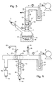
- FIGS. 1-8 are schematic drawings of exemplary plasma synthesis reactors that are useful in preparing bioactive compound mixtures.
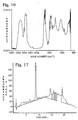
- FIGS. 9, 11, 12, 15, 17, 19, 20, 22, and 23 are high-performance liquid chromatography (HPLC) plots of absorbance versus time of organic compound mixtures prepared as described in Examples 1-9.
- FIGS. 10, 13, 16, and 18 are infrared spectra or organic compound mixtures prepared as described in Examples 1 and 3-5.
- FIG. 14 is a gas chromatography/mass spectroscopy chromatogram of the organic compound mixture prepared as described in Example 3.
- FIG. 21 is a HPLC/mass spectroscopy chromatogram of the organic compound mixture produced in Example 7.
- the invention comprises a process of preparing mixtures of bioactive organic compounds by interaction of a starting material with a high energy source.
- the process comprises plasma chemical synthesis.
- a single plasma chemical synthesis run is capable of producing a mixture of 2 to 100 and more diverse and complex organic compounds. Due to the nature of the plasma chemical synthesis process, an unlimited number of unique compound mixtures, comprising all classes of chemical structures and functional groups ( e . g ., aromatic, halogen, amide, ester, ketone, hydroxyl ether, mercaptan, cyclic rings containing hetero-atoms, etc.) can be produced.
- plasma is defined as partially ionized gas, light quanta radicals, and atomic and molecular species in various electronic excited states.
- the ionized species consist of positively charged molecules or atoms, and negatively charged electrons, and other ionized species such as negatively charged molecules and atoms and ionized molecular fragments.
- the recombination of plasma species through collisions with other plasma species, and with neutral molecules, both inside and outside of the plasma zone produces new chemical products and forms the basis of the plasma chemical synthesis process.
- any and all of the high-energy species that make up the plasma can induce reaction of starting material to produce products that make up the resulting mixture of compounds.
- starting material can interact with energy sources that are not strictly speaking considered plasma (e . g ., non-ionizing radiation, ionizing radiators or electric fields), but that have sufficient energy to induce reaction of the starting material and form complex product mixtures in a manner similar to plasma synthesis.
- Plasma may be produced by the action of a variety of ionizing agents on molecules and atoms. For example, all molecules and atoms become ionized when heated to temperatures of approximately 10,000°C or more. However, to prevent decomposition of organic compounds during their synthesis and recovery, the plasma temperature for a practical "cold" plasma organic chemical synthesis process should generally be limited tc approximately 350°C or less. However, in some cases, temperatures may exceed this temperature range as long as the period of time that species are at higher temperatures is very short, for example, on the order of less than 1 second. Cold plasmas are obtainable with an overall temperature of the neutral gaseous products below 350°C by lowering the gas pressure below 1 atmosphere.
- Suitable ionizing agents for producing cold plasmas include DC and AC electric discharges; high-energy light sources, such as lasers and electric discharge lamps that produce light in the microwave to x-ray frequency range; and charged particle beams, such as alpha particles produced in controlled nuclear reactions, and electron beams.
- a second major aspect of the present invention comprises subjecting the plasma-synthesized organic compound mixtures to bioactivity screening tests.
- bioactivity screening tests By testing mixtures of compounds, a large number of compounds are rapidly screened for a desired bioactivity. When a particular mixture tests positive for bioactivity, that mixture may then be separated into a number of smaller submixtures, or into fractions containing primarily a single compound. The bioactivity of each compound or submixture may be screened again in order to ultimately identify the particular compound that has the desired bioactivity.
- Once a fraction that contains primarily a single compound has been shown to be active, its molecular structure can be determined by conventional means such as single or multi-level mass spectroscopy (NMR, IR or UV/visible), and other related methods.
- the basic process for preparing mixtures of organic compounds by plasma chemical synthesis comprises the steps of: (1) introducing one or more organic reactants into a plasma synthesis reactor at an appropriate flow rate, and (2) subjecting the reactants to a plasma to form a mixture of product organic compounds.
- the plasma may be formed with (1) the entire mixture of reactants, (2) only a portion of the reactants, or (3) an inert gas such as argon.
- the components that form the plasma are subsequently mixed with any remaining reactants.
- a key parameter in generating useful mixtures involves controlling the time of contact of the reactants with the plasma. Various methods of obtaining the desired contact time to obtain a high yield of new compounds that have the desired properties are disclosed.
- preferred reactants for producing a plasma include any organic or inorganic compound that exhibits a vapor pressure of at least 13.3Pa (0.1 torr)at a temperature below approximately 350°C.
- Organic compounds include gases, volatile and semi-volatile, liquids, and volatile solids, and of which may or may not possess intrinsic biological activity prior to being subjected to the plasma treatment.
- Exemplary organic compounds include propane, chlorodifluoromethane, acetone, phenol, pyridine, ethanol, benzene, butyl acetate, tetrahydrofuran, ortho-dichlorobenzene, cyclopentanone, allylamine, 5-norbornene-2-methanol, 2-imidazolidone, 9-vinylcarbazole, 3,4-dimethoxyphenethylamine, quinazoline, 2,3-dimethoxybenzylalcohol, resorcinol, olivetol, phenanthrene, pheneanthridine, 1,2,3,4-tetrahydroisoquinoline, 1,2,3,4-tetrahydronapthylamine, methylstearate, ethanolamine, toluene, acetic acid, acetaldehyde, methyl ethyl ketone, and 6-chloro-1-hexanol.
- these organic compounds ionize and are fragmented to form various excited-state species, such as high-energy electrons, positive and negative ions, radicals, and molecular species in electronically excited states.
- excited-state species can recombine directly, and form, through single or multiple collisions, an unlimited variety of new chemical structures, or they can recombine with non excited-state molecules in the gas, liquid, or solid state both within, or outside of, the plasma zone.
- Inorganic compounds and elements also include gases and volatile and semi-volatile liquids.
- Exemplary inorganic reactants include argon, helium, nitrogen, oxygen, water, ammonia, carbon tetrafluoride, hydrogen, carbon monoxide, carbon dioxide and carbon disulfide.
- excited-state species react directly with each other, or with non excited-state molecules to form new chemical structures.
- excited-state species resulting from a plasma containing water can introduce hydroxyl groups to starting materials or products of previous reactions to form new chemical structures;
- carbon tetrafluoride can introduce fluoro or trifluoromethane groups;
- oxygen can introduce carbonyl, ether, ketone, and various other oxygenated chemical groups;
- carbon disulfide can introduce thiol, mercapto, and disulfide groups, ammonia can introduce amine groups; nitrogen can introduce nitrile groups; and hydrogen can quench radical species to terminate the synthesis process and can chemically reduce various functional groups, such as carbonyl, alkene, and aromatic groups.
- Chemically inert inorganic elements can act as energy transfer reagents for producing new chemical structures.
- excited-state species formed in argon or helium plasmas can collide with non excited-state organic molecules, either within or outside of the plasma zone, to produce excited-state organic species.
- the excited-state organic species can then recombine directly, and form through single or multiple collisions, new chemical structures, or they can recombine with non excited-state molecules in the gas, liquid, or solid state both within, or outside of the plasma zone.
- the optimum flow of reactants into the plasma synthesis reactor is determined by the optimum residence time of reactants in the plasma zone, and by the plasma operating parameters of pressure and intensity of the ionization source. If the reactants spend too little time in the plasma zone, few collisions occur between reactants and excited-state species, and only a limited amount of products are formed. On the other hand, if the residence time is too long, an excessive number of collisions produces undesirable high molecular weight polymers which, in general, do not exhibit bioactivity.
- the optimum range of residence time for reactants in the plasma zone is from 0.001 to 10 seconds, with a preferred range of from 0.01 to 2 seconds.
- the optimum range of pressure for plasma chemical synthesis is from 6.7Pa to 1.3kPa (0.05 to 10 torr), with a preferred range of from 13.3 to 400 Pa (0.01 to 3 torr).
- 6.7Pa 0.05 torr
- the practical upper limit of pressure is fixed by the plasma temperature and the thermal stability of the complex organic products. For example, through plasma reactor experimentation, it has been discovered that a plasma pressure of approximately 1.3kPa (10 torr) results in a plasma temperature of approximately 350°C. This temperature corresponds to the thermal stability limit of most organic compounds.
- a plasma pressure of approximately 1.3kPa (10 torr) results in a plasma temperature of approximately 350°C. This temperature corresponds to the thermal stability limit of most organic compounds.
- 101.3kPa 1 atmosphere
- One common method for producing a stable, long-lived plasma is by applying a strong electric field to the reactants in the gas or vapor phase.
- the strong electric field is typically generated by applying a high frequency voltage source to two ring electrodes that are placed along the plasma reactor, oriented coaxially with respect to the flow of reactants.
- the ring electrodes can be constructed from strips of electrically conductive material, such as copper, brass, aluminum, or steel, with preferred dimensions of approximately 2 cm wide and 0.1 to 0.5 cm thick, and sufficient length to be bent into a circle approximately 0.5 to 5.0 cm in diameter.
- the ring electrodes are placed around the interior or exterior of the plasma reactor in the desired region for the plasma zone.
- the electrodes are constructed from copper, brass, aluminum, or steel tubing from 0.2 to 2 cm diameter and cooling water is passed through the annulus of the electrode.
- the spacing between the two ring electrodes may range from 1 to 50 cm, with a preferred range of 4 to 20 cm.
- the high frequency voltage source consists of an impedance matching network and a high frequency power supply that is capable of supplying from 10 to 5,000 watts of power at a frequency of from 1 kHz to 100 MHz.
- the preferred frequency range for internal electrodes is from 10 kHz to 50 MHz, and the preferred frequency range for external electrodes is from 10 MHz to 50 MHz.
- the plasma discharge power must be increased with increasing pressure, increasing reactant flow rate, and with increasing size of the plasma zone.
- the preferred plasma discharge power is generally the minimum level which gives a stable plasma discharge and produces at least 1% conversion of the reactants to new product compounds within 4 hours reaction time.
- a preferred range of plasma discharge power for a reactor having a plasma zone volume of approximately 1 liter is from 50 to 500 watts.
- FIG. 1 an exemplary reactor for gas, vapor, and liquid reactants.
- the reactor consists of a glass vacuum flask 1 with reactant inlet 2 and condenser 3. Cooling for condenser 3 is maintained by cooling jacket 4, provided with coolant inlet 4a and outlet 4b; the coolant may be cool air, cool water, or other cooling fluid. Gas or vapor reactants enter the reactor through the reactant inlet opening 5 and flow control valve 6. The desired reactor pressure, which is monitored by pressure gauge 7, is established by opening pressure control valve 8 to vacuum pump 9. Starting material liquid reactant 10 is then brought to a gentle reflux condition by stirring with magnetic stir bar 11 and heating with heating mantle 12.
- Vapor from the refluxing liquid reactant 10 condenses on the walls of condenser 3 and flows down the walls of the condenser and vacuum flask 1 until it rejoins the pool of liquid reactant 10. Any solid that melts below 350°C, or semi-volatile liquid that exhibits a vapor pressure from 13.3kPa to 1.3kPa (0.1 to 10 torr) within the temperature range from 25 to 350°C is a suitable liquid reactant.
- a plasma zone 13 (shown by dashed lines) is established by the high frequency voltage source 14 and external ring electrodes 15.
- Plasma synthesis products are formed by reaction of excited-state species from the plasma zone and by reaction of excited-state species with reactant vapor from refluxing liquid 10. Products are trapped and removed from further reaction in the plasma zone, and are recovered by dissolving in the refluxing liquid and flowing to the liquid pool in vacuum flask 1. Highly volatile products are collected in cold trap 16, that is supercooled in cooling bath 17; preferably cooling bath 17 is maintained at either about -80°C by a dry ice slush or at about -200°C by liquid nitrogen.
- FIG. 2 shows another exemplary reactor for gas, vapor, and liquid reactants. It is similar in design to the reactor shown in FIG. 1 except for the design and placement of glass vacuum flask 1, reactant inlet 2, and external ring electrodes 15.
- vapor from refluxing liquid reagent 10 must pass through the plasma zone 13 before it condenses on the walls of condenser 3. This results in production of excited-state reactants from liquid reagent 10 as well as from gas or vapor reactants entering the reactor through reactant inlet opening 5.
- This additional source of excited-state reactants can produce a different range of products compared to use of the same reactants in the reactor shown in FIG. 1.
- FIG. 3 shows another exemplary reactor for gas, vapor, and liquid reactants. It also is similar in design to the reactor shown in FIG. 1 except for the placement of external ring electrodes 15 around the most active liquid reflux region within condenser 3.
- a mixture of vapor from refluxing liquid 10 and gas or vapor reactants entering the reactor through reactant inlet opening 5 enter plasma zone 13 to form excited-state species.
- Plasma synthesis products are formed by reaction between excited-state species in the plasma zone and by reaction between excited-state species and ground-state reactant molecules. Products are trapped and removed from further reaction in the plasma zone, by dissolving in the refluxing liquid film coating the condenser walls and flowing to the liquid pool in vacuum flask 1.
- FIG. 4 shows an exemplary reactor useful in preparing compound mixtures from gas and vapor reactants.
- This reactor requires all reactants to be in the gas or vapor state at a temperature below 350°C.
- the reactor consists of a heated glass vacuum manifold 1 with multiple reactant inlets 2a, 2b, and 2c.
- the vacuum manifold and reactant inlets are heated to a temperature of up to 350°C by a stream of hot air, by application of electric heating coils, or by immersion in a hot oil bath.
- Gas or vapor reactants enter the reactor through reactant inlet openings 5a, 5b, and 5c and flow control valves 6a, 6b, and 6c.
- the desired reactor pressure which is monitored by pressure gauge 7, is established by opening pressure control valve 8 to vacuum pump 9.
- a plasma zone 13 is established by the high frequency voltage source 14 and external, or internal ring electrodes 15. This reactor provides for a number of useful reactant flow schemes to produce a wide variety of plasma synthesis products.
- reactants entering the reactor through reactant inlet 2b form excited-state species in the plasma zone and produce products by reaction between excited-state species and by reaction of excited-state species with ground-state reactant molecules.
- excited-state species formed in the first flow scheme can react with ground-state molecules entering the reactor from both reactant inlets 2a and 2b.
- An alternative to the second flow scheme is to control and expand the volume of the plasma zone 18 to include formation of excited-state species from reactants entering the reactor through reactant inlet 2a. Control of the volume of the plasma zone is accomplished by applying a variable and controlled impedance 19 to ground 20 for auxiliary internal or external grounded electrode 21.
- FIG. 5 shows an exemplary reactor useful in preparing compound mixtures from gas, vapor, and solid reactants.
- This reactor requires one or more of the reactants to be a granular solid at a temperature above 100°C, and requires at least one other reactant in the gas or vapor state at a temperature below the melting point of the solid reactants.
- the reactor consists of a glass vacuum manifold 1 with reactant inlet 2. Gas or vapor reactants enter the reactor through the reactant inlet opening 5 and flow control valve 6. The flow rate of the gas or vapor reactants is adjusted so that a fluidized bed 22 of solid reactants 23 is maintained within the plasma zone 13 and coalescing filters 24.
- the desired reactor pressure which is monitored by pressure gauge 7, is established by opening pressure control valve 8 to vacuum pump 9.
- a plasma zone 13 is established by the high frequency voltage source 14 and external, or internal ring electrodes 15. Products are produced within the plasma zone by reaction of excited-state species in the gas or vapor phase with the solid reactants at the surface of the fluidized granules. The production of product mixtures from the solid reactants continues as the solid granules are continuously removed from, and reintroduced to, the plasma zone by the action of the fluidized bed. The products are recovered directly from the reactor space between the coalescing filters 24 by turning off the plasma and fluidizing gas or vapor reactants at the optimum reaction time. Highly volatile products are collected in cold trap 16.
- FIG. 6 shows an exemplary reactor that is useful for reacting gas, vapor, volatile liquid, and solid reactants. It is similar in design to the reactor shown in FIG. 5, except for the addition of a second gas or vapor reactant inlet 2b and continuous introduction of solid reactants 23 by spraying a concentrated solution or slurry of the solid reactants into the plasma zone.
- solid reactants 23 are sprayed into the plasma zone between coalescing filters 24 by introducing a concentrated solution or slurry of the solid reactants 25 into liquid pump 26 and spray head 27.
- the concentrated solution, or slurry of solid reactants 25 contains at least 10 wt% solid reactants in a solvent that readily volatilizes in the reactor to produce a fine granular fluidized bed of solid reactants 22.
- Suitable volatile solvents include water, acetone, diethyl ether, toluene, hexane, dichloromethane, and tetrahydrofuran.
- the fluidized bed is maintained by the spraying and devolitilization process, as well as by introduction of gas or vapor reactants through reactant inlet opening 5a. Excited-state species are therefore formed in the plasma zone 13 from gas or vapor reactants entering the reactor through reactant inlet opening 5a, and from solvent vapor from devolitilization of the concentrated solution or slurry of solid reactants 25.
- a second source of gas or vapor reactants may be introduced to the plasma zone through reactant inlet opening 5b. This second source of reactants produces additional excited-state species in the plasma zone 13 and the gas or vapor flow may also be used to control movement of fine solid reagent granules back down into the plasma zone.
- FIG. 7 shows another exemplary reactor that is useful for reacting gas, vapor, and solid reactants.
- solid reactants 23 are contained in shallow pan 28 within vacuum manifold 1.
- the shallow pan is located in plasma zone 13, which is maintained by high frequency voltage source 14a and by external or internal ring electrodes 15a.
- Vibration generator 29 is connected to pan 28 to provide constant mixing of the granular solid reactants and exposure of unreacted granular solid to the plasma.
- Gas and vapor reactants enter the reactor through the reactant inlet openings 5a and 5b and flow control valves 6a and 6b. Products are produced within the plasma zone by reaction of excited-state species from the gas or vapor phase with the solid reactants at the surface of the tumbling solid reactant granules.
- excited-state species may be formed mainly from gas and vapor reactants entering the reactor at reactant inlet opening 5b, and the solid reactants can be kept out of the plasma zone, by eliminating plasma zone 13 and forming plasma zone 30 through application of high frequency voltage source 14b to internal or external ring electrodes 15b.
- the products are recovered directly from pan 28 by turning off the plasma at the optimum reaction time.
- FIG. 8 is a schematic of still another exemplary reactor that is particularly designed to create a plasma to induce reaction of one or more low-volatility reactants. It comprises a pair of metal rods or plates 15 with smooth surfaces substantially parallel to each other and a relatively short distance (less than 1 mm) apart that serve as electrodes. One or more solid reactants 23 can be placed on the surface of the lower electrode. The remaining space between the electrodes can contain another gas-phase reactant or an inert gas such as argon, which enter through reactant inlet opening 5 and flow control valve 8. A plasma is generated and reaction initiated by a short-lived (0.001 to 1.0 second) DC discharge from one or more capacitors 32.
- a short-lived 0.001 to 1.0 second
- the DC discharge is formed by first opening circuit switches 30 and closing switches 31 so that capacitor 32 is charged by DC voltage source 14.
- the short-lived DC discharge is then produced by opening switches 31 and closing switches 30.
- the plasma is generated by ionization of the gaseous materials or the volatilized reactants. During such a discharge, very high temperatures may be reached, causing rapid reaction of the low-volatility solid reactants, but the temperature rapidly returns to near ambient temperature, thereby preventing undesirable thermal decomposition of the products.
- reactants can be excited by a variety of energy sources such as high intensity radiation with wavelengths in the visible or ultraviolet ranges.
- the apparatus would be modified so that one or more of the reactants would be passed through an activation zone where high intensity radiation would interact with the reactants. This may be accomplished, for example, by passing a laser beam through the wall of the reactor at a point relatively transparent to the laser radiation. This light can interact with the reactants in much the same way as the high frequency voltage source to ionize or fragment a portion of the reactants to initiate reaction.
- the basic process for screening plasma-synthesized mixtures for bioactivity comprises the steps:
- the crude product mixtures produced in the reactors described above can contain from near zero to 99% unreacted starting material and inert polymeric material, in addition to from 1 to 100 or more principal new products. However, typically the amount of unreacted starting material and inert polymeric is 50% to 99%. Bioactivity screening tests require as little as 100 nanograms or less of each new product, and so conversion of as little as 1% of the reactants to new products represents an acceptable yield. However, in many cases it is desirable to remove insoluble material, separate reactants that are present in large quantity from the new products, and to fractionate very large product mixtures into a number of mixtures that contain fewer compounds prior to bioactivity screening. A number of conventional laboratory procedures may be used to prepare and fractionate crude product mixtures prior to initial bioactivity screening tests.
- activity is screened by contacting the mixture of compounds with one of the following: a cell receptor, a cloned cell receptor, a biopolymer (protein, peptide, carbohydrate or nucleic acid), a model complexing agent for a bioreceptor or other biopolymer, an enzyme, a biological membrane or an organism.
- a cell receptor a cloned cell receptor
- a biopolymer protein, peptide, carbohydrate or nucleic acid
- a model complexing agent for a bioreceptor or other biopolymer an enzyme, a biological membrane or an organism.
- the tests generally involve contacting a solution of the mixture of compounds to be tested with a bioreceptor, enzyme, or organism, and measuring enhancement or inhibition of binding to the bioreceptor, chemical activity of the enzyme, or activity of the organism.
- Useful activities include: binding, inhibition of binding, enzyme inhibition, enzyme enhancement inhibition of biopolymer interaction, enhancement of biopolymer interaction, translocation across a biological membrane, enhancement of genetic expression, inhibition of genetic expression, inhibition of growth or activity of an organism and enhancement of growth or activity of an organism.
- cell receptors, cloned cell receptors, or model complexing agents for bioreceptors may be complexed with a radio-labeled ligand.
- the bioreceptor complex is then added to a solution containing the mixture of test compounds and bioactivity is indicated by the appearance of uncomplexed radio-labeled ligand in the solution due to its displacement from the bioreceptor by a test compound.
- Tests using biologically important enzymes involve adding test compounds to a solution containing the enzyme and all of the reactants that are involved in the specific enzymatic reaction of interest. Bioactivity is indicated when addition of the test compounds produces an enhancement, or inhibition, of the enzymatic reaction as measured by the conversion rate of reactants to products.
- Tests using organisms involve adding the organism to a solution or culture broth containing test compounds and measuring the activity (growth or mortality) of the organism.
- the organism could be bacteria for bioactivity tests for new potent antibiotics, or plant cells for bioactivity tests for development of new plant growth hormones.
- High throughput screening (screening as many as 10,000 new compounds in one week) is accomplished by using robotic equipment to perform routine sample preparation and analysis tasks, and by performing individual tests on mixtures of 10 to 100 or more compounds at once. In this manner, a single negative test (i.e., no bioactivity found) can confirm that 100 or more test compounds do not show the desired bioactivity.
- Compound mixtures that do show the desired bioactivity are fractionated, for example, by using the methods noted above, and the fractions, sub-fractions, and finally, individual fractionated compounds are retested to determine which compound or compounds show the desired bioactivity.
- a product mixture containing at least 20 new compounds suitable for bioactivity screening tests was synthesized using the plasma synthesis reactor shown in FIG. 4.
- Acetylene gas, water vapor, and ammonia gas were introduced to the reactor through reactant inlet opening 5b at 50, 180, and 340 cm 3 (STP)/min, respectively.
- the pressure was adjusted to 400Pa (3.0 torr) and 150 watts of plasma discharge power at 50 kHz was applied to 4.4 cm-diameter tubular internal electrodes that were spaced 21 cm apart, and cooled by the circulation of cold water through the annulus of the tubular electrodes.
- a product mixture containing at least 35 new compounds suitable for bioactivity screening was synthesized using the plasma synthesis reactor shown in FIG. 4. Cyclopentanone and allylamine vapors were introduced to the reactor through reactant inlet opening 5b at 100 and 30 cm 3 (STP)/min, respectively. Pressure was adjusted to 133.3Pa (1.0 torr) and 200_watts of plasma discharge power at 50 kHz was applied to 4.4 cm-diameter tubular, water-cooled internal electrodes spaced 20 cm apart. After 35 minutes reaction time a dark brown liquid product mixture was recovered from cold trap 16 in a 4% yield based on the quantity of reactants fed into the reactor. The HPLC chromatogram, using UV detection at 214 nm, of the product mixture is shown in FIG. 11. This chromatogram demonstrates that the product mixture contained at least 35 new compounds.
- This Example serves as a comparison to Example 3 and demonstrates the direct conversion of vapor reactants to new products by passing all reactants through a plasma that is sustained by internal electrodes.
- Example 2 was substantially repeated except cyclopentanone and allylamine vapors were introduced to the reactor through reactant inlet opening 5c, argon gas was introduced to the reactor through reactant inlet opening 5b at 50 cm 3 (STP)/min, the pressure was 266.6Pa (2.0 torr), and the reaction time was 1.5 hours.
- a transparent red oily liquid product was recovered from cold trap 16 in a 26% yield based on the quantity of reactants fed into the reactor.
- the HPLC chromatogram, using UV detection at 214 nm, of the product mixture is shown in FIG. 12. This chromatogram demonstrates that the product mixture contained at least 30 new compounds that are distinct from the compounds produced in Example 2.
- FIG. 13 The IR spectrum of the product mixture, after distillation to remove unreacted cyclohexanone and allylamine, is shown in FIG. 13. This spectrum shows that the new compounds in the product mixture contained amine, olefin, methyl, methylene, aldehyde, alkyne, allene, ester, and ketone functional groups.
- FIGS. 14a and 14b The results of GC/MS analysis of the product mixture, after distillation, is shown in FIGS. 14a and 14b.
- FIG. 14a shows the GC chromatogram of the sample and demonstrates the resolution of at least 28 new compounds.
- FIG. 14b shows the mass spectrum of compounds eluting the gas chromatograph at 21.16 minutes. The indicated mass of the molecular ion, or highest mass fragment was 343 daltons.
- a product mixture containing at least 29 new compounds suitable for bioactivity screening was synthesized using the plasma synthesis reactor shown in FIG. 3.
- 5-Norbornene-2-methanol (10 g) and 2-imidazolidone (10 g) were added to vacuum flask 1.
- the pressure was adjusted to 133.3Pa (1.0 torr) and heating mantle 12 was set so that the flask temperature was maintained at approximately 80°C, whereupon the reactants formed a gently refluxing viscous amber solution.
- a plasma was formed near the bottom of condenser 3 within the reflux zone of the reactants by applying 50 watts of plasma discharge power at 13.56 MHz to 3.5 cm diameter external electrodes spaced 12 cm apart.
- the HPLC chromatogram, using UV detection at 214 nm, of the product mixture is shown in FIG. 15. This chromatogram demonstrates that the crude product mixture contains at least 29 new compounds.
- the crude product mixture was then dissolved in diethylether and extracted with water to remove unreacted 2-imidazolidone.
- the ether phase was then distilled at ambient pressure to remove the diethylether, then at hard vacuum and 75°C to remove unreacted 5-norbornene-2-methanol, to produce an amber resinous product which was confirmed by HPLC analysis to be free of the initial reactants.
- the infrared spectrum of the purified product mixture is shown in FIG. 16.
- This spectrum shows that the new compounds in the product mixture contained hydroxyl, olefin, methyl, methylene, carbonyl, and amine functional groups.
- This Example demonstrates the direct conversion of low-volatility liquid and low-melting solid reactants to new products by refluxing all the reactants within a plasma that is sustained by external electrodes.
- a product mixture containing at least 20 new compounds suitable for bioactivity screening was synthesized using the plasma synthesis reactor shown in FIG. 1.
- 5 Norbornene-2-methanol (15 g) was added to vacuum flask 1 and difluoromethane gas was introduced into the reactor through reactant inlet opening 5 at 400 cm 3 (STP)/min.
- the pressure was adjusted to 133.3Pa (1.0 torr) and heating mantle 12 was set so that the flask temperature was maintained at approximately 80°C, whereupon the 5-norbornene-2-methanol reactant formed a gently refluxing viscous amber solution.
- a plasma was formed within reactant inlet 2 by applying 100 watts of plasma discharge power at 13.56 MHz to 3.5 cm diameter external electrodes that were spaced 8 cm apart.
- a product mixture containing at least 120 new compounds suitable for bioactivity screening was synthesized using the plasma synthesis reactor shown in FIG. 3.
- Resorcinol (5 g) and 1,2,3,4-tetrahydro-1-napthylamine (5 g) were added to vacuum flask 1.
- Pressure was adjusted to 20Pa (0.15 torr) and heating mantle 12 was set so that the flask temperature was maintained at approximately 120°C, whereupon the reactants formed a gently refluxing amber solution.
- a plasma was formed near the bottom of condenser 3 within the reflux zone of the reactants by applying 140 watts of plasma discharge power at 13.56 MHz to 3.5 cm diameter external electrodes spaced 4 cm apart. After 2.75 hours reaction time, 6.5 g of a glassy red-brown solid product mixture was recovered from flask 1.
- a sample of the crude product mixture was dissolved in a solution of 50% acetonitrile in water, filtered to remove insoluble matter, and analyzed by HPLC.
- the HPLC chromatogram, using UV detection at 254 nm, of the filtered product mixture is shown in FIG. 19. This chromatogram demonstrates that the crude product mixture contained at least 120 new compounds.
- the filtered product mixture was then fractionated by HPLC to remove unreacted resorcinol and 1,2,3,4-tetrahydro-1-napthylamine.
- the fractions containing the new product compounds were pooled and tested for bioactivity in receptor competitive-binding tests. At least one compound in this product mixture was found to be active for binding to the cannabis CB-1 receptor, and to the opioid K-type receptor.
- This Example demonstrates the direct conversion of two low-volatility liquid reactants and one high-volatility liquid reactant, to new products that are bioactive, by refluxing all reactants within a plasma that is sustained by external electrodes.
- Example 6 was substantially repeated except that 1,2,3,4-tetrahydroisoquinoline (5.0 g) and olivetol (4.5 g) were added to vacuum flask 1, the pressure was 66.7Pa (0.50 torr), and the reaction time was 4 hours. The resulting synthesis left 8.8 g of a dark amber-brown semi-solid product.
- a sample of the crude product mixture was dissolved in a solution of 50% acetonitrile in water, filtered to remove insoluble matter, and analyzed by HPLC. The HPLC chromatogram, using UV detection at 254 nm, of the filtered product mixture is shown in FIG. 20. This chromatogram demonstrates that the crude product mixture contained at least 129 new compounds.
- FIG. 21 An HPLC/MSn chromatogram of the filtered product mixture is shown in FIG. 21. This chromatogram confirms the production of new compounds with molecular weights that range from 132 daltons to 570 daltons.
- the filtered product mixture was then fractionated by HPLC to remove unreacted 1,2,3,4-tetrahydroisoquinoline and olivetol.
- the fractions containing the new product compounds were pooled and tested for bioactivity in receptor binding tests. At least one compound in this product mixture was found to be active for binding to the cannabis CB-1 receptor, and to the opioid K-type receptor.
- Example 6 was substantially repeated except that 9-vinylcarbazole (5.0 g) and 3,4-dimethoxyphenethylamine (5.0 g) were added to vacuum flask 1, argon was introduced into the reactor through reactant inlet opening 5 at 10.8 cm 3 (STP)/min, the pressure was 133.3Pa (1.0 torr), the power was 100 watts, and the reaction time was 4 hours.
- the resulting synthesis left 7.4 g of a viscous transparent red solution that formed a red semi-solid product upon cooling.
- a sample of the crude product mixture was dissolved in a solution qf 50% acetonitrile in water, filtered to remove insoluble matter, and analyzed by HPLC.
- the HPLC chromatogram, using UV detection at 254 nm, of the filtered product mixture is shown in FIG. 22. This chromatogram demonstrates that the crude product mixture contained at least 126 new compounds.
- the filtered product mixture was then fractionated by HPLC to remove unreacted 9-vinylcarbazole and 3,4-dimethoxyphenethylamine. The fractions containing the new product compounds were pooled and tested for bioactivity in receptor binding tests. At least one compound in this product mixture was found to be active for binding to the opioid K-type receptor.
- Example 6 was substantially repeated except resorcinol (5.0 g) and olivetol (4.5 g) were added to vacuum flask 1, the pressure was 133.3Pa (1.0 torr), the power was 250 watts, and the reaction time was 4 hours. The resulting synthesis left 8.8 g of a dark red-brown oily liquid product.
- a sample of the crude product mixture was dissolved in a solution of 50% acetonitrile in water, filtered to remove insoluble matter, and analyzed by HPLC. The HPLC chromatogram, using UV detection at 254 nm, of the filtered product mixture is shown in FIG. 23. This chromatogram demonstrates that the crude product mixture contained at least 237 new compounds.
- the filtered product mixture was then fractionated by HPLC to remove unreacted resorcinol and olivetol.
- the fractions containing the new product compounds were pooled and tested for bioactivity in receptor binding tests. A compound, or compounds in this product mixture was found to be active for binding to the opioid K-type receptor.
Landscapes
- Chemical & Material Sciences (AREA)
- Organic Chemistry (AREA)
- Chemical Kinetics & Catalysis (AREA)
- Health & Medical Sciences (AREA)
- Engineering & Computer Science (AREA)
- Life Sciences & Earth Sciences (AREA)
- Biochemistry (AREA)
- General Chemical & Material Sciences (AREA)
- Medicinal Chemistry (AREA)
- Molecular Biology (AREA)
- Physics & Mathematics (AREA)
- Fluid Mechanics (AREA)
- Plasma & Fusion (AREA)
- General Health & Medical Sciences (AREA)
- Toxicology (AREA)
- Structural Engineering (AREA)
- Organic Low-Molecular-Weight Compounds And Preparation Thereof (AREA)
- Nitrogen And Oxygen Or Sulfur-Condensed Heterocyclic Ring Systems (AREA)
- Measuring Or Testing Involving Enzymes Or Micro-Organisms (AREA)
- Physical Or Chemical Processes And Apparatus (AREA)
Description
- Modern drug discovery has been revolutionized by the development of high-throughput screening techniques. The ability to clone receptors, combined with modern automation techniques, means that now thousands of compounds can be screened for receptor binding and, by extension, pharmaceutical activity, in the time previously required to screen only a few. Hodgson, 10 Biotech. 973 (1992). Because of this screening capacity, new compound generation is now often the rate-limiting step in drug discovery. Dewitt, 1 Pharm. News 11 (1994). In addition, the statistics of this screening approach to drug discovery requires the testing of many thousands of compounds in order to discover one highly active new compound. The traditional sources of compounds for screening, such as natural products or the products of rational drug design, cannot furnish the numbers of compounds needed to meet this demand, while combinatorial synthesis produces large numbers of compounds but they have insufficient diversity of structures. The present invention is directed at the development of a new method to synthesize and screen large numbers of structurally diverse compounds.
- There are two principal ways in which candidate compounds are currently provided for drug screening: isolation from natural products, and chemical synthesis. Natural products, such as plant extracts, provide a great amount of structural diversity. However, this approach typically requires laborious sample collection and preparation, followed by difficulties in identification, isolation, and production of compounds determined to be active via screening. Consequently, this approach is typically too slow to meet the capacity offered by high-throughput screening. Traditional chemical synthesis is also slow, and new technologies--primarily combinatorial approaches to stepwise synthesis--are being developed to rapidly generate collections of molecules for drug discovery. Dewitt, Ibid. Such combinatorial approaches can provide sufficient quantities of compounds quickly enough for high-throughput screening, but the structural diversity is restricted due to the limited number of starting materials and synthetic reactions for combining starting materials.
- Plasma glow discharges have been used to prepare specific compounds from vaporized organic reactants. See, for example, Cvetanovic, 1 Adv. Photochem. 115 (1963) wherein the production of an aldhyde, two epoxides and two ketones from a mixture of 2-pentene and oxygen was reported. See also, Suhr, 11 Angew. Chem. Int. Ed. Eng1. 781 (1972), which discloses the limited production of several cyclic compounds from acetylene; however, unless the reaction is rapidly quenched, the primary products are polymers. Ibid. The primary focus of prior attempts to synthesize new products by exposure of one or more reactants to a glow discharge has been to maximize conversion and yield of a single desired product which, due to the inherent difficulty in controlling plasma discharge reactions, has been largely unsuccessful. The present invention is based upon the recognition that such inherent uncontrollability can be used to advantage in preparing a multitude of organic compounds containing diverse chemical structures and functional groups, and that the resultant product mix, when coupled with bioactivity screening, can ultimately lead to the production of significant numbers of useful compounds.
- The present invention comprises a novel process for synthesizing and identifying compounds with desirable bioactivity. Such compounds are useful in many areas of science and industry, such as the areas of drug discovery, toxicity testing, development of animal and plant growth hormones, and pesticide and herbicide development. The present invention utilizes a new, fast, low-cost method for the generation of mixtures of large numbers of unique compounds in the laboratory: plasma synthesis. As with natural sources of extracts, plasma synthesis promises to provide compounds with an extremely wide variety of structures for testing, but does not require laborious biological-sample collection and preparation. Sample generation may be conducted in the laboratory using small scale apparatus and a wide range of commonly available starting materials. Production of larger samples of promising bioactive materials will therefore be greatly simplified. Because of the high-energy synthesis procedures used, highly diverse structures can be generated from simple starting materials, yet reaction conditions can be adjusted such that the number of products, their molecular weights, and their chemical properties can be controlled. In addition, the number of unique compounds that can be generated using low-cost apparatus rivals that of the best combinatorial techniques.
- The process envisioned for synthesis of compound mixtures is not strictly limited to plasma synthesis, but encompasses the interaction of a starting material with any high-energy source that can induce reaction of the starting material to produce a diverse set of products.
- For example, a plasma itself is a complex environment. Starting materials exposed to a plasma can interact with ionizing radiation (e.g., radiation of sufficient energy to induce ionization of molecules such as ultraviolet (UV) or higher energy light), non-ionizing radiation (e.g., lower energy radiation that generally does not induce ionization such as near UV or visible light) and electric fields (e.g., those from radio frequency, audio frequency, alternating current or direct current), all of which may be present in the plasma. Any and all of these can impart sufficient energy to the starting materials to induce reactions to form new compounds that are different from the starting material.
- According to the present invention there is provided a method for forming and assaying organic compounds for biological activity characterized by the steps:
- (a) introducing a starting material comprising at least one organic compound to a plasma zone for a residence time of from 0.001 to 10 seconds to form a product mixture of organic compounds containing at least one organic compound that is not said starting material; and
- (b) assaying said product mixture for biological
activity by the following steps:
- (i) contacting said product mixture with an agent selected from the group consisting of a cell receptor; a cloned cell receptor; a biopolymer selected from the group consisting of a protein, a peptide, a carbohydrate and a nucleic acid; a model complexing agent for bioreceptor; an enzyme; a biological membrane; and an organism; and
- (ii) determining whether any compound in said product mixture exhibits an activity selected from the group of activities consisting of binding, inhibition of binding, enzyme inhibition, enzyme enhancement, inhibition of biopolymer interaction, enhancement of biopolymer interaction, translocation across a biological membrane, inhibition of translocation across a biological membrane, enhancement of genetic expression, inhibition of genetic expression, inhibition of the growth or activity of an organism, and enhancement of the growth or activity of an organism.
-
- The process comprises two main steps: (1) the production of organic compound mixtures of unlimited number and diversity by plasma chemical synthesis; and (2) subjecting these compound mixtures to screening tests for a desired biological activity. Once a particular mixture tests positive for desirable activity, the mixture is separated into its individual components by common chemical separation techniques, such as chromatography or extraction, and each component is then retested to determine which ones have activity.
- FIGS. 1-8 are schematic drawings of exemplary plasma synthesis reactors that are useful in preparing bioactive compound mixtures.
- FIGS. 9, 11, 12, 15, 17, 19, 20, 22, and 23 are high-performance liquid chromatography (HPLC) plots of absorbance versus time of organic compound mixtures prepared as described in Examples 1-9.
- FIGS. 10, 13, 16, and 18 are infrared spectra or organic compound mixtures prepared as described in Examples 1 and 3-5.
- FIG. 14 is a gas chromatography/mass spectroscopy chromatogram of the organic compound mixture prepared as described in Example 3.
- FIG. 21 is a HPLC/mass spectroscopy chromatogram of the organic compound mixture produced in Example 7.
- There are essentially two features of the present invention. In one aspect, the invention comprises a process of preparing mixtures of bioactive organic compounds by interaction of a starting material with a high energy source. In particular, the process comprises plasma chemical synthesis. When conducted in accordance with the methods described in the present invention, a single plasma chemical synthesis run is capable of producing a mixture of 2 to 100 and more diverse and complex organic compounds. Due to the nature of the plasma chemical synthesis process, an unlimited number of unique compound mixtures, comprising all classes of chemical structures and functional groups (e.g., aromatic, halogen, amide, ester, ketone, hydroxyl ether, mercaptan, cyclic rings containing hetero-atoms, etc.) can be produced.
- For the purposes of the present invention, plasma is defined as partially ionized gas, light quanta radicals, and atomic and molecular species in various electronic excited states. The ionized species consist of positively charged molecules or atoms, and negatively charged electrons, and other ionized species such as negatively charged molecules and atoms and ionized molecular fragments. The recombination of plasma species through collisions with other plasma species, and with neutral molecules, both inside and outside of the plasma zone produces new chemical products and forms the basis of the plasma chemical synthesis process.
- Any and all of the high-energy species that make up the plasma can induce reaction of starting material to produce products that make up the resulting mixture of compounds. In addition, simpler processes can be envisioned wherein starting material can interact with energy sources that are not strictly speaking considered plasma (e.g., non-ionizing radiation, ionizing radiators or electric fields), but that have sufficient energy to induce reaction of the starting material and form complex product mixtures in a manner similar to plasma synthesis.
- Plasma may be produced by the action of a variety of ionizing agents on molecules and atoms. For example, all molecules and atoms become ionized when heated to temperatures of approximately 10,000°C or more. However, to prevent decomposition of organic compounds during their synthesis and recovery, the plasma temperature for a practical "cold" plasma organic chemical synthesis process should generally be limited tc approximately 350°C or less. However, in some cases, temperatures may exceed this temperature range as long as the period of time that species are at higher temperatures is very short, for example, on the order of less than 1 second. Cold plasmas are obtainable with an overall temperature of the neutral gaseous products below 350°C by lowering the gas pressure below 1 atmosphere. Suitable ionizing agents for producing cold plasmas include DC and AC electric discharges; high-energy light sources, such as lasers and electric discharge lamps that produce light in the microwave to x-ray frequency range; and charged particle beams, such as alpha particles produced in controlled nuclear reactions, and electron beams.
- A second major aspect of the present invention comprises subjecting the plasma-synthesized organic compound mixtures to bioactivity screening tests. By testing mixtures of compounds, a large number of compounds are rapidly screened for a desired bioactivity. When a particular mixture tests positive for bioactivity, that mixture may then be separated into a number of smaller submixtures, or into fractions containing primarily a single compound. The bioactivity of each compound or submixture may be screened again in order to ultimately identify the particular compound that has the desired bioactivity. Once a fraction that contains primarily a single compound has been shown to be active, its molecular structure can be determined by conventional means such as single or multi-level mass spectroscopy (NMR, IR or UV/visible), and other related methods.
- The basic process for preparing mixtures of organic compounds by plasma chemical synthesis comprises the steps of: (1) introducing one or more organic reactants into a plasma synthesis reactor at an appropriate flow rate, and (2) subjecting the reactants to a plasma to form a mixture of product organic compounds.
- The plasma may be formed with (1) the entire mixture of reactants, (2) only a portion of the reactants, or (3) an inert gas such as argon. In the case of options (2) and (3), the components that form the plasma are subsequently mixed with any remaining reactants. A key parameter in generating useful mixtures involves controlling the time of contact of the reactants with the plasma. Various methods of obtaining the desired contact time to obtain a high yield of new compounds that have the desired properties are disclosed.
- In the present invention, preferred reactants for producing a plasma include any organic or inorganic compound that exhibits a vapor pressure of at least 13.3Pa (0.1 torr)at a temperature below approximately 350°C. Organic compounds include gases, volatile and semi-volatile, liquids, and volatile solids, and of which may or may not possess intrinsic biological activity prior to being subjected to the plasma treatment. Exemplary organic compounds include propane, chlorodifluoromethane, acetone, phenol, pyridine, ethanol, benzene, butyl acetate, tetrahydrofuran, ortho-dichlorobenzene, cyclopentanone, allylamine, 5-norbornene-2-methanol, 2-imidazolidone, 9-vinylcarbazole, 3,4-dimethoxyphenethylamine, quinazoline, 2,3-dimethoxybenzylalcohol, resorcinol, olivetol, phenanthrene, pheneanthridine, 1,2,3,4-tetrahydroisoquinoline, 1,2,3,4-tetrahydronapthylamine, methylstearate, ethanolamine, toluene, acetic acid, acetaldehyde, methyl ethyl ketone, and 6-chloro-1-hexanol. In the plasma, these organic compounds ionize and are fragmented to form various excited-state species, such as high-energy electrons, positive and negative ions, radicals, and molecular species in electronically excited states. These excited-state species can recombine directly, and form, through single or multiple collisions, an unlimited variety of new chemical structures, or they can recombine with non excited-state molecules in the gas, liquid, or solid state both within, or outside of, the plasma zone.
- Inorganic compounds and elements also include gases and volatile and semi-volatile liquids. Exemplary inorganic reactants include argon, helium, nitrogen, oxygen, water, ammonia, carbon tetrafluoride, hydrogen, carbon monoxide, carbon dioxide and carbon disulfide.
- In the case of chemically reactive compounds, such as water and carbon tetrafluoride, excited-state species react directly with each other, or with non excited-state molecules to form new chemical structures. For example, excited-state species resulting from a plasma containing water can introduce hydroxyl groups to starting materials or products of previous reactions to form new chemical structures; carbon tetrafluoride can introduce fluoro or trifluoromethane groups; oxygen can introduce carbonyl, ether, ketone, and various other oxygenated chemical groups; carbon disulfide can introduce thiol, mercapto, and disulfide groups, ammonia can introduce amine groups; nitrogen can introduce nitrile groups; and hydrogen can quench radical species to terminate the synthesis process and can chemically reduce various functional groups, such as carbonyl, alkene, and aromatic groups.
- Chemically inert inorganic elements, such as argon and helium, can act as energy transfer reagents for producing new chemical structures. For example, excited-state species formed in argon or helium plasmas can collide with non excited-state organic molecules, either within or outside of the plasma zone, to produce excited-state organic species. The excited-state organic species can then recombine directly, and form through single or multiple collisions, new chemical structures, or they can recombine with non excited-state molecules in the gas, liquid, or solid state both within, or outside of the plasma zone.
- Key variables that influence the nature of the compound mixtures produced by the plasma chemical synthesis process include the flow rate of reactants into the plasma zone, the total pressure in the plasma zone, and the amount of energy that is applied to sustain the plasma. The optimum flow of reactants into the plasma synthesis reactor is determined by the optimum residence time of reactants in the plasma zone, and by the plasma operating parameters of pressure and intensity of the ionization source. If the reactants spend too little time in the plasma zone, few collisions occur between reactants and excited-state species, and only a limited amount of products are formed. On the other hand, if the residence time is too long, an excessive number of collisions produces undesirable high molecular weight polymers which, in general, do not exhibit bioactivity. Through experimentation, we have discovered that the optimum range of residence time for reactants in the plasma zone is from 0.001 to 10 seconds, with a preferred range of from 0.01 to 2 seconds. Using this range, the optimum flow of reactants can be calculated by dividing the volume of the plasma zone by the residence time. For example, with a plasma synthesis reactor operated at 133.3Pa (1.0 torr) pressure and containing a plasma zone 1.5 cm in diameter and 6 cm long, for a desired residence time of 0.05 second the desired flow rate of the reactants would be πr2L/tP, or [6 cm x 3.14 x (1.5 cm/2)2]/0.05 second x [1 torr/760 torr (STP)] = 0.28 cm3 (STP)/second.
- The optimum range of pressure for plasma chemical synthesis is from 6.7Pa to 1.3kPa (0.05 to 10 torr), with a preferred range of from 13.3 to 400 Pa (0.01 to 3 torr). Below 6.7Pa (0.05 torr) the low collision rate between reactants and excited-state species results in an undesirably low production rate of products. While higher pressure increases the production rate, the plasma temperature also increases. The practical upper limit of pressure is fixed by the plasma temperature and the thermal stability of the complex organic products. For example, through plasma reactor experimentation, it has been discovered that a plasma pressure of approximately 1.3kPa (10 torr) results in a plasma temperature of approximately 350°C. This temperature corresponds to the thermal stability limit of most organic compounds. However, by modifying the geometry of the reactor and minimizing the residence time of reactants within the plasma zone, one may successfully operate at pressures up to 101.3kPa (1 atmosphere), or even higher.
- One common method for producing a stable, long-lived plasma is by applying a strong electric field to the reactants in the gas or vapor phase. The strong electric field is typically generated by applying a high frequency voltage source to two ring electrodes that are placed along the plasma reactor, oriented coaxially with respect to the flow of reactants. The ring electrodes can be constructed from strips of electrically conductive material, such as copper, brass, aluminum, or steel, with preferred dimensions of approximately 2 cm wide and 0.1 to 0.5 cm thick, and sufficient length to be bent into a circle approximately 0.5 to 5.0 cm in diameter. The ring electrodes are placed around the interior or exterior of the plasma reactor in the desired region for the plasma zone. When electrode cooling is desired, especially in the case of interior electrodes, the electrodes are constructed from copper, brass, aluminum, or steel tubing from 0.2 to 2 cm diameter and cooling water is passed through the annulus of the electrode. The spacing between the two ring electrodes may range from 1 to 50 cm, with a preferred range of 4 to 20 cm.
- The high frequency voltage source consists of an impedance matching network and a high frequency power supply that is capable of supplying from 10 to 5,000 watts of power at a frequency of from 1 kHz to 100 MHz. The preferred frequency range for internal electrodes is from 10 kHz to 50 MHz, and the preferred frequency range for external electrodes is from 10 MHz to 50 MHz. In general, the plasma discharge power must be increased with increasing pressure, increasing reactant flow rate, and with increasing size of the plasma zone. The preferred plasma discharge power is generally the minimum level which gives a stable plasma discharge and produces at least 1% conversion of the reactants to new product compounds within 4 hours reaction time. A preferred range of plasma discharge power for a reactor having a plasma zone volume of approximately 1 liter is from 50 to 500 watts.
- In order to take full advantage of the unlimited diversity of chemical structures that may be produced by the plasma chemical synthesis method, a variety of exemplary plasma synthesis reactors have been devised that allow reactions to occur between gaseous, liquid, and solid reactants.
- Referring to the drawings, wherein like numerals refer to the same elements, there is shown in FIG. 1 an exemplary reactor for gas, vapor, and liquid reactants. The reactor consists of a
glass vacuum flask 1 withreactant inlet 2 andcondenser 3. Cooling forcondenser 3 is maintained by coolingjacket 4, provided withcoolant inlet 4a andoutlet 4b; the coolant may be cool air, cool water, or other cooling fluid. Gas or vapor reactants enter the reactor through thereactant inlet opening 5 and flowcontrol valve 6. The desired reactor pressure, which is monitored bypressure gauge 7, is established by openingpressure control valve 8 tovacuum pump 9. Startingmaterial liquid reactant 10 is then brought to a gentle reflux condition by stirring withmagnetic stir bar 11 and heating withheating mantle 12. Vapor from the refluxingliquid reactant 10 condenses on the walls ofcondenser 3 and flows down the walls of the condenser andvacuum flask 1 until it rejoins the pool ofliquid reactant 10. Any solid that melts below 350°C, or semi-volatile liquid that exhibits a vapor pressure from 13.3kPa to 1.3kPa (0.1 to 10 torr) within the temperature range from 25 to 350°C is a suitable liquid reactant. A plasma zone 13 (shown by dashed lines) is established by the highfrequency voltage source 14 andexternal ring electrodes 15. - Plasma synthesis products are formed by reaction of excited-state species from the plasma zone and by reaction of excited-state species with reactant vapor from refluxing
liquid 10. Products are trapped and removed from further reaction in the plasma zone, and are recovered by dissolving in the refluxing liquid and flowing to the liquid pool invacuum flask 1. Highly volatile products are collected incold trap 16, that is supercooled in coolingbath 17; preferably coolingbath 17 is maintained at either about -80°C by a dry ice slush or at about -200°C by liquid nitrogen. - FIG. 2 shows another exemplary reactor for gas, vapor, and liquid reactants. It is similar in design to the reactor shown in FIG. 1 except for the design and placement of
glass vacuum flask 1,reactant inlet 2, andexternal ring electrodes 15. In this reactor configuration, vapor from refluxingliquid reagent 10 must pass through theplasma zone 13 before it condenses on the walls ofcondenser 3. This results in production of excited-state reactants fromliquid reagent 10 as well as from gas or vapor reactants entering the reactor throughreactant inlet opening 5. This additional source of excited-state reactants can produce a different range of products compared to use of the same reactants in the reactor shown in FIG. 1. - FIG. 3 shows another exemplary reactor for gas, vapor, and liquid reactants. It also is similar in design to the reactor shown in FIG. 1 except for the placement of
external ring electrodes 15 around the most active liquid reflux region withincondenser 3. In this reactor configuration, a mixture of vapor from refluxingliquid 10 and gas or vapor reactants entering the reactor throughreactant inlet opening 5, enterplasma zone 13 to form excited-state species. Plasma synthesis products are formed by reaction between excited-state species in the plasma zone and by reaction between excited-state species and ground-state reactant molecules. Products are trapped and removed from further reaction in the plasma zone, by dissolving in the refluxing liquid film coating the condenser walls and flowing to the liquid pool invacuum flask 1. Since the plasma zone is located within the most active liquid reflux region of the reactor there is greater contact between excited-state species and vapor from refluxingliquid 10. In addition, the vigorously refluxing liquid improves the trapping and removal of products from the plasma zone. These reactor features can result in production of a still different range of products compared to use of the same reactants in the reactor shown in FIGS. 1 and 2. - FIG. 4 shows an exemplary reactor useful in preparing compound mixtures from gas and vapor reactants. This reactor requires all reactants to be in the gas or vapor state at a temperature below 350°C. The reactor consists of a heated
glass vacuum manifold 1 withmultiple reactant inlets reactant inlet openings flow control valves pressure gauge 7, is established by openingpressure control valve 8 tovacuum pump 9. Aplasma zone 13 is established by the highfrequency voltage source 14 and external, orinternal ring electrodes 15. This reactor provides for a number of useful reactant flow schemes to produce a wide variety of plasma synthesis products. - In the simplest flow scheme, reactants entering the reactor through
reactant inlet 2b form excited-state species in the plasma zone and produce products by reaction between excited-state species and by reaction of excited-state species with ground-state reactant molecules. In a second flow scheme, excited-state species formed in the first flow scheme can react with ground-state molecules entering the reactor from bothreactant inlets plasma zone 18 to include formation of excited-state species from reactants entering the reactor throughreactant inlet 2a. Control of the volume of the plasma zone is accomplished by applying a variable and controlledimpedance 19 to ground 20 for auxiliary internal or external groundedelectrode 21. - Yet another series of flow schemes are made possible by combining any of the above flow schemes with introduction of ground state reactant molecules into the reactor through
reactant inlet 2c. This last series of flow schemes allows for quenching of residual excited state products by ground state reactant molecules entering the reactor fromreactant inlet 2c, down stream from the plasma zone. Products produced in any of the above flow schemes are removed from further reaction in the plasma zone and trapped by convective flow of reactants through the plasma zone to thecold trap 16. - FIG. 5 shows an exemplary reactor useful in preparing compound mixtures from gas, vapor, and solid reactants. This reactor requires one or more of the reactants to be a granular solid at a temperature above 100°C, and requires at least one other reactant in the gas or vapor state at a temperature below the melting point of the solid reactants. The reactor consists of a
glass vacuum manifold 1 withreactant inlet 2. Gas or vapor reactants enter the reactor through thereactant inlet opening 5 and flowcontrol valve 6. The flow rate of the gas or vapor reactants is adjusted so that afluidized bed 22 ofsolid reactants 23 is maintained within theplasma zone 13 and coalescing filters 24. The desired reactor pressure, which is monitored bypressure gauge 7, is established by openingpressure control valve 8 tovacuum pump 9. Aplasma zone 13 is established by the highfrequency voltage source 14 and external, orinternal ring electrodes 15. Products are produced within the plasma zone by reaction of excited-state species in the gas or vapor phase with the solid reactants at the surface of the fluidized granules. The production of product mixtures from the solid reactants continues as the solid granules are continuously removed from, and reintroduced to, the plasma zone by the action of the fluidized bed. The products are recovered directly from the reactor space between the coalescingfilters 24 by turning off the plasma and fluidizing gas or vapor reactants at the optimum reaction time. Highly volatile products are collected incold trap 16. - FIG. 6 shows an exemplary reactor that is useful for reacting gas, vapor, volatile liquid, and solid reactants. It is similar in design to the reactor shown in FIG. 5, except for the addition of a second gas or
vapor reactant inlet 2b and continuous introduction ofsolid reactants 23 by spraying a concentrated solution or slurry of the solid reactants into the plasma zone. In this reactor configuration,solid reactants 23 are sprayed into the plasma zone between coalescingfilters 24 by introducing a concentrated solution or slurry of thesolid reactants 25 intoliquid pump 26 andspray head 27. The concentrated solution, or slurry ofsolid reactants 25 contains at least 10 wt% solid reactants in a solvent that readily volatilizes in the reactor to produce a fine granular fluidized bed ofsolid reactants 22. Suitable volatile solvents include water, acetone, diethyl ether, toluene, hexane, dichloromethane, and tetrahydrofuran. The fluidized bed is maintained by the spraying and devolitilization process, as well as by introduction of gas or vapor reactants through reactant inlet opening 5a. Excited-state species are therefore formed in theplasma zone 13 from gas or vapor reactants entering the reactor through reactant inlet opening 5a, and from solvent vapor from devolitilization of the concentrated solution or slurry ofsolid reactants 25. Alternatively, a second source of gas or vapor reactants may be introduced to the plasma zone through reactant inlet opening 5b. This second source of reactants produces additional excited-state species in theplasma zone 13 and the gas or vapor flow may also be used to control movement of fine solid reagent granules back down into the plasma zone. - FIG. 7 shows another exemplary reactor that is useful for reacting gas, vapor, and solid reactants. In this reactor configuration,
solid reactants 23 are contained inshallow pan 28 withinvacuum manifold 1. The shallow pan is located inplasma zone 13, which is maintained by highfrequency voltage source 14a and by external orinternal ring electrodes 15a.Vibration generator 29 is connected to pan 28 to provide constant mixing of the granular solid reactants and exposure of unreacted granular solid to the plasma. Gas and vapor reactants enter the reactor through thereactant inlet openings control valves plasma zone 13 and formingplasma zone 30 through application of highfrequency voltage source 14b to internal orexternal ring electrodes 15b. The products are recovered directly frompan 28 by turning off the plasma at the optimum reaction time. - FIG. 8 is a schematic of still another exemplary reactor that is particularly designed to create a plasma to induce reaction of one or more low-volatility reactants. It comprises a pair of metal rods or
plates 15 with smooth surfaces substantially parallel to each other and a relatively short distance (less than 1 mm) apart that serve as electrodes. One or moresolid reactants 23 can be placed on the surface of the lower electrode. The remaining space between the electrodes can contain another gas-phase reactant or an inert gas such as argon, which enter throughreactant inlet opening 5 and flowcontrol valve 8. A plasma is generated and reaction initiated by a short-lived (0.001 to 1.0 second) DC discharge from one ormore capacitors 32. The DC discharge is formed by first opening circuit switches 30 and closing switches 31 so thatcapacitor 32 is charged byDC voltage source 14. The short-lived DC discharge is then produced by openingswitches 31 and closing switches 30. The plasma is generated by ionization of the gaseous materials or the volatilized reactants. During such a discharge, very high temperatures may be reached, causing rapid reaction of the low-volatility solid reactants, but the temperature rapidly returns to near ambient temperature, thereby preventing undesirable thermal decomposition of the products. - An important feature of the plasma synthesis processes and reactors described herein is that synthesis conditions have been shown to be sufficiently controlled that product mixtures can be reproduced. Thus, product mixtures produced under nominally ideal conditions at different times have been shown to contain substantially the same compounds in substantially the same relative amounts.
- Many other reactor types are envisioned as being useful in carrying out the invention. For example, reactants can be excited by a variety of energy sources such as high intensity radiation with wavelengths in the visible or ultraviolet ranges. In such cases, the apparatus would be modified so that one or more of the reactants would be passed through an activation zone where high intensity radiation would interact with the reactants. This may be accomplished, for example, by passing a laser beam through the wall of the reactor at a point relatively transparent to the laser radiation. This light can interact with the reactants in much the same way as the high frequency voltage source to ionize or fragment a portion of the reactants to initiate reaction.
- As to the screening aspect of the present invention, the basic process for screening plasma-synthesized mixtures for bioactivity comprises the steps:
- (a) preparing the crude compound mixture for initial bioactivity screening tests;
- (b) performing initial bioactivity screening tests on the crude compound mixture to determine if desired activity is present;
- (c) if the desired activity is present, fractionating the crude compound mixture, testing each fraction for bioactivity, and refractionating and testing the active fractions until isolated compounds are found that show desired bioactivity; and
- (d) identifying the isolated compounds that show the desired bioactivity.
-
- The crude product mixtures produced in the reactors described above can contain from near zero to 99% unreacted starting material and inert polymeric material, in addition to from 1 to 100 or more principal new products. However, typically the amount of unreacted starting material and inert polymeric is 50% to 99%. Bioactivity screening tests require as little as 100 nanograms or less of each new product, and so conversion of as little as 1% of the reactants to new products represents an acceptable yield. However, in many cases it is desirable to remove insoluble material, separate reactants that are present in large quantity from the new products, and to fractionate very large product mixtures into a number of mixtures that contain fewer compounds prior to bioactivity screening. A number of conventional laboratory procedures may be used to prepare and fractionate crude product mixtures prior to initial bioactivity screening tests. These include solvent extraction, dissolution, and simple filtration to remove objectionable polymeric and tar-like materials; high performance liquid chromatography (HPLC), column chromatography, size-exclusion chromatography, distillation, fractional crystallization, electrophoresis, and gas chromatography to fractionate very large product mixtures and to remove reactants that may be present in large excess. The crude product mixtures may also be evaluated for the yield and number of new products using these fractionation procedures in addition to gas chromatography/mass spectroscopy (GC/MS) and the relatively new technique of liquid chromatography/multistage mass spectroscopy (LC/MSn).
- There are a wide variety of conventional tests that have been developed to measure bioactivity. These tests are readily available and may be conducted using methods known to those skilled in the art, as described for example in Houghten, 13 Biotech. 412-421 (1992). In fact, the science and technology of bioactivity screening has progressed to the extent that companies exist, such as CEREP Inc., Celle I'Evescault, France, that can conduct a wide variety of specific bioactivity screening tests on customer's samples on a contract basis. In general, according to the invention, activity is screened by contacting the mixture of compounds with one of the following: a cell receptor, a cloned cell receptor, a biopolymer (protein, peptide, carbohydrate or nucleic acid), a model complexing agent for a bioreceptor or other biopolymer, an enzyme, a biological membrane or an organism.
- The tests generally involve contacting a solution of the mixture of compounds to be tested with a bioreceptor, enzyme, or organism, and measuring enhancement or inhibition of binding to the bioreceptor, chemical activity of the enzyme, or activity of the organism. Useful activities include: binding, inhibition of binding, enzyme inhibition, enzyme enhancement inhibition of biopolymer interaction, enhancement of biopolymer interaction, translocation across a biological membrane, enhancement of genetic expression, inhibition of genetic expression, inhibition of growth or activity of an organism and enhancement of growth or activity of an organism.
- For example, cell receptors, cloned cell receptors, or model complexing agents for bioreceptors may be complexed with a radio-labeled ligand. The bioreceptor complex is then added to a solution containing the mixture of test compounds and bioactivity is indicated by the appearance of uncomplexed radio-labeled ligand in the solution due to its displacement from the bioreceptor by a test compound. Tests using biologically important enzymes involve adding test compounds to a solution containing the enzyme and all of the reactants that are involved in the specific enzymatic reaction of interest. Bioactivity is indicated when addition of the test compounds produces an enhancement, or inhibition, of the enzymatic reaction as measured by the conversion rate of reactants to products. Tests using organisms involve adding the organism to a solution or culture broth containing test compounds and measuring the activity (growth or mortality) of the organism. For example, the organism could be bacteria for bioactivity tests for new potent antibiotics, or plant cells for bioactivity tests for development of new plant growth hormones.
- High throughput screening (screening as many as 10,000 new compounds in one week) is accomplished by using robotic equipment to perform routine sample preparation and analysis tasks, and by performing individual tests on mixtures of 10 to 100 or more compounds at once. In this manner, a single negative test (i.e., no bioactivity found) can confirm that 100 or more test compounds do not show the desired bioactivity. Compound mixtures that do show the desired bioactivity are fractionated, for example, by using the methods noted above, and the fractions, sub-fractions, and finally, individual fractionated compounds are retested to determine which compound or compounds show the desired bioactivity.
- Once the compound or compounds that exhibit the desired bioactivity are isolated, their specific identity and chemical structure is determined using conventional laboratory techniques that include elemental analysis, nuclear magnetic resonance (NMR) spectroscopy, infrared (IR) spectroscopy, and mass spectroscopy (MSn).
- A product mixture containing at least 20 new compounds suitable for bioactivity screening tests was synthesized using the plasma synthesis reactor shown in FIG. 4. Acetylene gas, water vapor, and ammonia gas were introduced to the reactor through reactant inlet opening 5b at 50, 180, and 340 cm3 (STP)/min, respectively. The pressure was adjusted to 400Pa (3.0 torr) and 150 watts of plasma discharge power at 50 kHz was applied to 4.4 cm-diameter tubular internal electrodes that were spaced 21 cm apart, and cooled by the circulation of cold water through the annulus of the tubular electrodes. After 2 hours reaction time a red-brown oily product mixture was recovered from
cold trap 16 in a 9.2% yield based on the quantity of acetylene fed into the reactor. The HPLC chromatogram, using UV detection at 230 nm, of the product mixture is shown in FIG. 9. By virtue of its absorption peaks, this chromatogram demonstrates that the product mixture contained at least 20 new compounds. The infrared spectrum of the product mixture is shown in FIG. 10, which reveals that the new compounds in the product mixture contained hydroxyl, amine, amide, methyl, methylene, terminal and branched alkyne and allene functional groups. This Example demonstrates the direct conversion of gas and vapor reactants to a multiplicity of new products by passing all reactants through a plasma formed from the reactants themselves that is sustained by internal electrodes. - A product mixture containing at least 35 new compounds suitable for bioactivity screening was synthesized using the plasma synthesis reactor shown in FIG. 4. Cyclopentanone and allylamine vapors were introduced to the reactor through reactant inlet opening 5b at 100 and 30 cm3 (STP)/min, respectively. Pressure was adjusted to 133.3Pa (1.0 torr) and 200_watts of plasma discharge power at 50 kHz was applied to 4.4 cm-diameter tubular, water-cooled internal electrodes spaced 20 cm apart. After 35 minutes reaction time a dark brown liquid product mixture was recovered from
cold trap 16 in a 4% yield based on the quantity of reactants fed into the reactor. The HPLC chromatogram, using UV detection at 214 nm, of the product mixture is shown in FIG. 11. This chromatogram demonstrates that the product mixture contained at least 35 new compounds. This Example serves as a comparison to Example 3 and demonstrates the direct conversion of vapor reactants to new products by passing all reactants through a plasma that is sustained by internal electrodes. - Example 2 was substantially repeated except cyclopentanone and allylamine vapors were introduced to the reactor through reactant inlet opening 5c, argon gas was introduced to the reactor through reactant inlet opening 5b at 50 cm3 (STP)/min, the pressure was 266.6Pa (2.0 torr), and the reaction time was 1.5 hours. A transparent red oily liquid product was recovered from
cold trap 16 in a 26% yield based on the quantity of reactants fed into the reactor. The HPLC chromatogram, using UV detection at 214 nm, of the product mixture is shown in FIG. 12. This chromatogram demonstrates that the product mixture contained at least 30 new compounds that are distinct from the compounds produced in Example 2. The IR spectrum of the product mixture, after distillation to remove unreacted cyclohexanone and allylamine, is shown in FIG. 13. This spectrum shows that the new compounds in the product mixture contained amine, olefin, methyl, methylene, aldehyde, alkyne, allene, ester, and ketone functional groups. The results of GC/MS analysis of the product mixture, after distillation, is shown in FIGS. 14a and 14b. FIG. 14a shows the GC chromatogram of the sample and demonstrates the resolution of at least 28 new compounds. FIG. 14b shows the mass spectrum of compounds eluting the gas chromatograph at 21.16 minutes. The indicated mass of the molecular ion, or highest mass fragment was 343 daltons. The molecular weight of cylopentanone and allylamine are 84 and 57 daltons, respectively. Thus, the mass spectrum confirms the production of products that are substantially distinct from the reactants. This Example also demonstrates the indirect conversion of vapor reactants to new products by reaction downstream of the plasma zone, with inert gas excited-state species. - A product mixture containing at least 29 new compounds suitable for bioactivity screening was synthesized using the plasma synthesis reactor shown in FIG. 3. 5-Norbornene-2-methanol (10 g) and 2-imidazolidone (10 g) were added to
vacuum flask 1. The pressure was adjusted to 133.3Pa (1.0 torr) andheating mantle 12 was set so that the flask temperature was maintained at approximately 80°C, whereupon the reactants formed a gently refluxing viscous amber solution. A plasma was formed near the bottom ofcondenser 3 within the reflux zone of the reactants by applying 50 watts of plasma discharge power at 13.56 MHz to 3.5 cm diameter external electrodes spaced 12 cm apart. After 8 hours' reaction time the flask contained approximately 20 g of a dark amber semi-solid. The HPLC chromatogram, using UV detection at 214 nm, of the product mixture is shown in FIG. 15. This chromatogram demonstrates that the crude product mixture contains at least 29 new compounds. The crude product mixture was then dissolved in diethylether and extracted with water to remove unreacted 2-imidazolidone. The ether phase was then distilled at ambient pressure to remove the diethylether, then at hard vacuum and 75°C to remove unreacted 5-norbornene-2-methanol, to produce an amber resinous product which was confirmed by HPLC analysis to be free of the initial reactants. The infrared spectrum of the purified product mixture is shown in FIG. 16. This spectrum shows that the new compounds in the product mixture contained hydroxyl, olefin, methyl, methylene, carbonyl, and amine functional groups. This Example demonstrates the direct conversion of low-volatility liquid and low-melting solid reactants to new products by refluxing all the reactants within a plasma that is sustained by external electrodes. - A product mixture containing at least 20 new compounds suitable for bioactivity screening was synthesized using the plasma synthesis reactor shown in FIG. 1. 5 Norbornene-2-methanol (15 g) was added to
vacuum flask 1 and difluoromethane gas was introduced into the reactor through reactant inlet opening 5 at 400 cm3 (STP)/min. The pressure was adjusted to 133.3Pa (1.0 torr) andheating mantle 12 was set so that the flask temperature was maintained at approximately 80°C, whereupon the 5-norbornene-2-methanol reactant formed a gently refluxing viscous amber solution. A plasma was formed withinreactant inlet 2 by applying 100 watts of plasma discharge power at 13.56 MHz to 3.5 cm diameter external electrodes that were spaced 8 cm apart. After 1.5 hours reaction time the flask contained approximately 15 g of a dark semi-solid. The HPLC chromatogram, using UV detection at 214 nm, of the product mixture is shown in FIG. 17. This chromatogram demonstrates that the crude product mixture contained at least 20 new compounds. Unreacted 5-norbornene-2-methanol was removed from the crude product mixture by distillation at hard vacuum and 75°C to produce a dark solid resinous product. The IR spectrum of the purified product mixture is shown in FIG. 18. This spectrum shows that the new compounds in the product mixture contained hydroxyl, olefin, methyl, methylene, carbonyl, and fluoro functional groups. This Example demonstrates the conversion of a low volatility liquid reactant to new products by contacting the refluxing vapor with excited-state species produced by passing a reactive gaseous reactant through a plasma zone that is sustained by external electrodes. - A product mixture containing at least 120 new compounds suitable for bioactivity screening was synthesized using the plasma synthesis reactor shown in FIG. 3. Resorcinol (5 g) and 1,2,3,4-tetrahydro-1-napthylamine (5 g) were added to
vacuum flask 1. Hexanes (a commercial mixture of hexane isomers) vapor was then introduced into the reactor through reactant inlet opening 5 at 5.5 cm3 (STP)/min. Pressure was adjusted to 20Pa (0.15 torr) andheating mantle 12 was set so that the flask temperature was maintained at approximately 120°C, whereupon the reactants formed a gently refluxing amber solution. A plasma was formed near the bottom ofcondenser 3 within the reflux zone of the reactants by applying 140 watts of plasma discharge power at 13.56 MHz to 3.5 cm diameter external electrodes spaced 4 cm apart. After 2.75 hours reaction time, 6.5 g of a glassy red-brown solid product mixture was recovered fromflask 1. A sample of the crude product mixture was dissolved in a solution of 50% acetonitrile in water, filtered to remove insoluble matter, and analyzed by HPLC. The HPLC chromatogram, using UV detection at 254 nm, of the filtered product mixture is shown in FIG. 19. This chromatogram demonstrates that the crude product mixture contained at least 120 new compounds. The filtered product mixture was then fractionated by HPLC to remove unreacted resorcinol and 1,2,3,4-tetrahydro-1-napthylamine. The fractions containing the new product compounds were pooled and tested for bioactivity in receptor competitive-binding tests. At least one compound in this product mixture was found to be active for binding to the cannabis CB-1 receptor, and to the opioid K-type receptor. This Example demonstrates the direct conversion of two low-volatility liquid reactants and one high-volatility liquid reactant, to new products that are bioactive, by refluxing all reactants within a plasma that is sustained by external electrodes. - Example 6 was substantially repeated except that 1,2,3,4-tetrahydroisoquinoline (5.0 g) and olivetol (4.5 g) were added to
vacuum flask 1, the pressure was 66.7Pa (0.50 torr), and the reaction time was 4 hours. The resulting synthesis left 8.8 g of a dark amber-brown semi-solid product. A sample of the crude product mixture was dissolved in a solution of 50% acetonitrile in water, filtered to remove insoluble matter, and analyzed by HPLC. The HPLC chromatogram, using UV detection at 254 nm, of the filtered product mixture is shown in FIG. 20. This chromatogram demonstrates that the crude product mixture contained at least 129 new compounds. An HPLC/MSn chromatogram of the filtered product mixture is shown in FIG. 21. This chromatogram confirms the production of new compounds with molecular weights that range from 132 daltons to 570 daltons. The filtered product mixture was then fractionated by HPLC to remove unreacted 1,2,3,4-tetrahydroisoquinoline and olivetol. The fractions containing the new product compounds were pooled and tested for bioactivity in receptor binding tests. At least one compound in this product mixture was found to be active for binding to the cannabis CB-1 receptor, and to the opioid K-type receptor. - Example 6 was substantially repeated except that 9-vinylcarbazole (5.0 g) and 3,4-dimethoxyphenethylamine (5.0 g) were added to
vacuum flask 1, argon was introduced into the reactor through reactant inlet opening 5 at 10.8 cm3 (STP)/min, the pressure was 133.3Pa (1.0 torr), the power was 100 watts, and the reaction time was 4 hours. The resulting synthesis left 7.4 g of a viscous transparent red solution that formed a red semi-solid product upon cooling. A sample of the crude product mixture was dissolved in a solution qf 50% acetonitrile in water, filtered to remove insoluble matter, and analyzed by HPLC. The HPLC chromatogram, using UV detection at 254 nm, of the filtered product mixture is shown in FIG. 22. This chromatogram demonstrates that the crude product mixture contained at least 126 new compounds. The filtered product mixture was then fractionated by HPLC to remove unreacted 9-vinylcarbazole and 3,4-dimethoxyphenethylamine. The fractions containing the new product compounds were pooled and tested for bioactivity in receptor binding tests. At least one compound in this product mixture was found to be active for binding to the opioid K-type receptor. - Example 6 was substantially repeated except resorcinol (5.0 g) and olivetol (4.5 g) were added to
vacuum flask 1, the pressure was 133.3Pa (1.0 torr), the power was 250 watts, and the reaction time was 4 hours. The resulting synthesis left 8.8 g of a dark red-brown oily liquid product. A sample of the crude product mixture was dissolved in a solution of 50% acetonitrile in water, filtered to remove insoluble matter, and analyzed by HPLC. The HPLC chromatogram, using UV detection at 254 nm, of the filtered product mixture is shown in FIG. 23. This chromatogram demonstrates that the crude product mixture contained at least 237 new compounds. The filtered product mixture was then fractionated by HPLC to remove unreacted resorcinol and olivetol. The fractions containing the new product compounds were pooled and tested for bioactivity in receptor binding tests. A compound, or compounds in this product mixture was found to be active for binding to the opioid K-type receptor.
Claims (16)
- A method for forming and assaying organic compounds for biological activity characterized by the steps:(a) introducing a starting material comprising at least one organic compound to a plasma zone for a residence time of from 0.001 to 10 seconds to form a product mixture of organic compounds containing at least one organic compound that is not said starting material; and(b) assaying said product mixture for biological activity by the following steps:(i) contacting said product mixture with an agent selected from the group consisting of a cell receptor; a cloned cell receptor; a biopolymer selected from the group consisting of a protein, a peptide, a carbohydrate and a nucleic acid; a model complexing agent for bioreceptor; an enzyme; a biological membrane; and an organism; and(ii) determining whether any compound in said product mixture exhibits an activity selected from the group of activities consisting of binding, inhibition of binding, enzyme inhibition, enzyme enhancement, inhibition of biopolymer interaction, enhancement of biopolymer interaction, translocation across a biological membrane, inhibition of translocation across a biological membrane, enhancement of genetic expression, inhibition of genetic expression, inhibition of the growth or activity of an organism, and enhancement of the growth or activity of an organism.
- The method of claim 1 wherein said product mixture is separated into fractions prior to step (b) and assaying each of said fractions for biological activity.
- The method of claim 1 wherein said starting material includes at least one organic compound possessing biological activity.
- The method of claim 1 wherein said plasma zone is generated by a continuous electric field and said starting material passes through said plasma zone.
- The method of claim 4 wherein the residence time of said starting material in said plasma zone is from 0.01 to 2 seconds, the pressure of said plasma zone is from 0.05 to 10 torr, and the discharge power density of said plasma zone is from 10 to 5000 watts per liter of plasma zone volume.
- The method of claim 5 wherein said starting material reacts with plasma-activated species outside of said plasma zone.
- The method of claim I wherein said plasma zone is generated by a high energy light source emitting radiation in the frequency range of from 1010 to 1022 Hz and that is selected from a laser, an electric discharge lamp and an electron beam.
- The method of claim 1 wherein said plasma zone is generated by an alpha-particle beam.
- A plasma discharge reactor for forming biologically active organic compounds characterized by the following elements:(a) a vessel in fluid communication with a source of vacuum and provided with a valved reactant inlet, a condensor, a magnetic stirrer and a heater;(b) a cold trap in fluid communication with said condensor;(c) at least one source of plasma discharge; and(d) a pressure gauge.
- The reactor of claim 9 wherein said source of plasma discharge surrounds a portion of said reactor selected from said reactant inlet, said condensor and a portion of said reactant inlet and a portion of said condensor.
- The reactor of claim 9 characterized in that element (a) is replaced with a manifold in fluid communication with a source of vacuum and provided with at least one valved reactant inlet and a source of heat.
- The reactor of claim 11 wherein said source of plasma discharge surrounds at least one of said valved reactant inlets and including variable impedance means.
- The reactor of claim 9 characterized in that element (a) is replaced with a manifold in fluid communication with a source of vacuum and provided with at least one valved reactant inlet, a source of heat, and at least two coalescing filters.
- The reactor of claim 13 including a solids reactant spray inlet.
- The reactor of claim 9 characterized in that element (a) is replaced with a manifold in fluid communication with a source of vacuum and provided with two valved reactant inlets, and further characterized by a vessel within said manifold for receiving solids and a vibration generator operatively connected to said vessel.
- The reactor of claim 15 wherein said at least one source of plasma discharge comprises a pair of electrodes within said manifold for receiving solids, said electrodes being part of an electrical circuit comprising a DC voltage source, at least one capacitor, and switches between said electrodes and said at least one capacitor and between said DC voltage source and said at least one capacitor.
Applications Claiming Priority (2)
| Application Number | Priority Date | Filing Date | Title |
|---|---|---|---|
| US08/843,897 US5772855A (en) | 1997-04-17 | 1997-04-17 | Preparation of bioactive compounds by plasma synthesis |
| US843897 | 2001-04-26 |
Publications (2)
| Publication Number | Publication Date |
|---|---|
| EP0872464A1 EP0872464A1 (en) | 1998-10-21 |
| EP0872464B1 true EP0872464B1 (en) | 2001-11-14 |
Family
ID=25291275
Family Applications (1)
| Application Number | Title | Priority Date | Filing Date |
|---|---|---|---|
| EP98302942A Expired - Lifetime EP0872464B1 (en) | 1997-04-17 | 1998-04-16 | Preparation of bioactive compounds by plasma synthesis |
Country Status (5)
| Country | Link |
|---|---|
| US (2) | US5772855A (en) |
| EP (1) | EP0872464B1 (en) |
| JP (1) | JPH10338652A (en) |
| CA (1) | CA2234491C (en) |
| DE (1) | DE69802453T2 (en) |
Families Citing this family (15)
| Publication number | Priority date | Publication date | Assignee | Title |
|---|---|---|---|---|
| JP4636634B2 (en) * | 1996-04-26 | 2011-02-23 | ボストン サイエンティフィック サイムド,インコーポレイテッド | Intravascular stent |
| DE19734236C2 (en) * | 1996-09-14 | 2000-03-23 | Spinner Gmbh Elektrotech | Coaxial cable connector |
| KR20010105129A (en) * | 2000-05-19 | 2001-11-28 | 임승우 | Reformed rotatory vacuum evaporator with cryogenic and heat system |
| US6547979B1 (en) * | 2000-08-31 | 2003-04-15 | Micron Technology, Inc. | Methods of enhancing selectivity of etching silicon dioxide relative to one or more organic substances; and plasma reaction chambers |
| US6685803B2 (en) * | 2001-06-22 | 2004-02-03 | Applied Materials, Inc. | Plasma treatment of processing gases |
| US6858114B2 (en) | 2001-07-03 | 2005-02-22 | The University Of Alabama | Laser hydrolysis of polypeptides |
| WO2004089855A2 (en) * | 2003-04-07 | 2004-10-21 | Nanon A/S | Method of modifying chemical compounds by plasma in the liquid state |
| DE10319810A1 (en) * | 2003-04-30 | 2004-11-18 | Uhde Gmbh | Radical gas phase reaction reactor |
| GB0403797D0 (en) * | 2004-02-20 | 2004-03-24 | Boc Group Plc | Gas abatement |
| US20050265905A1 (en) * | 2004-04-20 | 2005-12-01 | Akribio Corp. | Multifunctional multireactor chemical synthesis instrument |
| US7641854B2 (en) * | 2004-04-20 | 2010-01-05 | Li Young | Multifunctional multireactor control system with dynamic multiple protocols, templates and digital notebooks and methodology |
| JP6131037B2 (en) * | 2012-12-20 | 2017-05-17 | ヤマト科学株式会社 | Reflux equipment |
| US11648729B2 (en) | 2019-06-03 | 2023-05-16 | The Boeing Company | Additive manufacturing powder particle, method for treating the additive manufacturing powder particle, and method for additive manufacturing |
| KR102619579B1 (en) * | 2021-08-11 | 2023-12-29 | 주식회사 피에스에스 | Plasma device for treating exhaust gas |
| WO2023096709A1 (en) | 2021-11-29 | 2023-06-01 | X Development Llc | Molecular structure transformers for property prediction |
Family Cites Families (11)
| Publication number | Priority date | Publication date | Assignee | Title |
|---|---|---|---|---|
| FR399913A (en) * | 1909-02-25 | 1909-07-10 | Paul Cramer | Improvements to reverse flame gas burners |
| US1754186A (en) * | 1925-05-20 | 1930-04-08 | Siemens Ag | Process of manufacturing drying varnishes |
| US2728723A (en) * | 1953-01-29 | 1955-12-27 | Gosta C Akerlof | Method and apparatus for the production of heat-sensitive substances in electrical glow discharges |
| US3305466A (en) * | 1965-07-26 | 1967-02-21 | Evans Ruthanna Mccoy | Method of and apparatus for reacting gas and solids |
| US4097384A (en) * | 1976-03-22 | 1978-06-27 | Northwestern University | Process for uranium isotope separation |
| US5143854A (en) * | 1989-06-07 | 1992-09-01 | Affymax Technologies N.V. | Large scale photolithographic solid phase synthesis of polypeptides and receptor binding screening thereof |
| US5284556A (en) * | 1991-05-01 | 1994-02-08 | Plasmachines, Inc. | Exhaust treatment system and method |
| CA2091665C (en) * | 1992-04-07 | 2003-01-07 | Peter George Tsantrizos | Process for the synthesis of fullerenes |
| FR2697448B1 (en) * | 1992-10-30 | 1995-06-16 | Moulinex Sa | Device for conducting chemical operations. |
| AU1560095A (en) * | 1994-01-06 | 1995-08-01 | Metabolix, Inc. | Methods for synthesizing oligomers containing hydroxy acid units |
| US5556752A (en) * | 1994-10-24 | 1996-09-17 | Affymetrix, Inc. | Surface-bound, unimolecular, double-stranded DNA |
-
1997
- 1997-04-17 US US08/843,897 patent/US5772855A/en not_active Expired - Fee Related
-
1998
- 1998-04-09 CA CA002234491A patent/CA2234491C/en not_active Expired - Fee Related
- 1998-04-16 EP EP98302942A patent/EP0872464B1/en not_active Expired - Lifetime
- 1998-04-16 DE DE69802453T patent/DE69802453T2/en not_active Expired - Fee Related
- 1998-04-16 JP JP10106534A patent/JPH10338652A/en active Pending
-
1999
- 1999-06-23 US US09/339,315 patent/US6221319B1/en not_active Expired - Fee Related
Also Published As
| Publication number | Publication date |
|---|---|
| EP0872464A1 (en) | 1998-10-21 |
| DE69802453D1 (en) | 2001-12-20 |
| US6221319B1 (en) | 2001-04-24 |
| JPH10338652A (en) | 1998-12-22 |
| US5772855A (en) | 1998-06-30 |
| DE69802453T2 (en) | 2002-07-18 |
| CA2234491C (en) | 2006-03-14 |
| CA2234491A1 (en) | 1998-10-17 |
Similar Documents
| Publication | Publication Date | Title |
|---|---|---|
| US6221319B1 (en) | Plasma discharge reactors for the preparation of bioactive compounds | |
| Howard et al. | Fullerenes synthesis in combustion | |
| US5534232A (en) | Apparatus for reactions in dense-medium plasmas | |
| Xu et al. | Phenylacetylene dendrimers by the divergent, convergent, and double-stage convergent methods | |
| Carl et al. | Binding energies for the inner hydration shells of Ca2+: An experimental and theoretical investigation of Ca2+ (H2O) x complexes (x= 5–9) | |
| Wathey et al. | The impact of microwave-assisted organic chemistry on drug discovery | |
| Warrener et al. | A tandem cycloaddition protocol for the controlled synthesis of [n] ladderanes: new rods and spacers | |
| Roque et al. | Switching on H-tunneling through conformational control | |
| Xie et al. | Microwave synthesis of fullerenes from chloroform | |
| Kozlov et al. | Synthesis of organic compounds from mixtures of methane with carbon dioxide in dielectric-barrier discharges at atmospheric pressure | |
| Chu et al. | Catalyst-free oxidation reactions in a microwave plasma torch-based ion/molecular reactor: an approach for predicting the atmospheric oxidation of pollutants | |
| Hendrix et al. | Cation, anion, and radical isomers of C4H4N: Computational characterization and implications for astrophysical and planetary environments | |
| Shapero et al. | Benzyl radical photodissociation dynamics at 248 nm | |
| Coll et al. | Report and implications of the first observation of C4N2 in laboratory simulations of Titan’s atmosphere | |
| Rap et al. | Noncovalent interactions steer the formation of polycyclic aromatic hydrocarbons | |
| Lafleur et al. | Bacterial and human cell mutagenicity study of some C18H10 cyclopenta-fused polycyclic aromatic hydrocarbons associated with fossil fuels combustion | |
| Suhr | Applications and trends of nonequilibrium plasma chemistry with organic and organometallic compounds | |
| Moore et al. | Ultraviolet photodissociation of proteinogenic amino acids | |
| Yang et al. | Low-Temperature Gas-Phase Formation of Methanimine (CH2NH; X1A′)─ the Simplest Imine─ under Single-Collision Conditions | |
| Kerisit et al. | Synthesis, Chemistry, and Photochemistry of Methylcyanobutadiyne in the Context of Space Science | |
| Baranová et al. | Next generation of dielectric barrier discharge hydride atomizers for atomic absorption spectrometry: A case study on Pb, Bi, Se and Te | |
| Spare et al. | Chemoselective flow hydrogenation approaches to diversify the cytotoxic tetrahydroepoxyisoindole carboxamide scaffold | |
| Biglova et al. | Kinetic study of the reaction of nucleophilic cyclopropanation of C60 fullerene with halogenated maleopimarimide | |
| Peltonen et al. | Free radicals from photodecomposition of bisphenol‐A | |
| Miller | Organic plasma chemistry |
Legal Events
| Date | Code | Title | Description |
|---|---|---|---|
| PUAI | Public reference made under article 153(3) epc to a published international application that has entered the european phase |
Free format text: ORIGINAL CODE: 0009012 |
|
| AK | Designated contracting states |
Kind code of ref document: A1 Designated state(s): BE CH DE DK FR GB IE IT LI NL SE |
|
| AX | Request for extension of the european patent |
Free format text: AL;LT;LV;MK;RO;SI |
|
| 17P | Request for examination filed |
Effective date: 19981127 |
|
| AKX | Designation fees paid |
Free format text: AT BE CH DE DK ES FI FR GB GR LI |
|
| RBV | Designated contracting states (corrected) |
Designated state(s): BE CH DE DK FR GB IE IT LI NL SE |
|
| 17Q | First examination report despatched |
Effective date: 20000218 |
|
| GRAG | Despatch of communication of intention to grant |
Free format text: ORIGINAL CODE: EPIDOS AGRA |
|
| GRAG | Despatch of communication of intention to grant |
Free format text: ORIGINAL CODE: EPIDOS AGRA |
|
| GRAH | Despatch of communication of intention to grant a patent |
Free format text: ORIGINAL CODE: EPIDOS IGRA |
|
| GRAH | Despatch of communication of intention to grant a patent |
Free format text: ORIGINAL CODE: EPIDOS IGRA |
|
| GRAH | Despatch of communication of intention to grant a patent |
Free format text: ORIGINAL CODE: EPIDOS IGRA |
|
| GRAH | Despatch of communication of intention to grant a patent |
Free format text: ORIGINAL CODE: EPIDOS IGRA |
|
| GRAA | (expected) grant |
Free format text: ORIGINAL CODE: 0009210 |
|
| AK | Designated contracting states |
Kind code of ref document: B1 Designated state(s): BE CH DE DK FR GB IE IT LI NL SE |
|
| PG25 | Lapsed in a contracting state [announced via postgrant information from national office to epo] |
Ref country code: NL Free format text: LAPSE BECAUSE OF FAILURE TO SUBMIT A TRANSLATION OF THE DESCRIPTION OR TO PAY THE FEE WITHIN THE PRESCRIBED TIME-LIMIT Effective date: 20011114 Ref country code: BE Free format text: LAPSE BECAUSE OF FAILURE TO SUBMIT A TRANSLATION OF THE DESCRIPTION OR TO PAY THE FEE WITHIN THE PRESCRIBED TIME-LIMIT Effective date: 20011114 |
|
| REG | Reference to a national code |
Ref country code: CH Ref legal event code: EP |
|
| REG | Reference to a national code |
Ref country code: IE Ref legal event code: FG4D |
|
| REF | Corresponds to: |
Ref document number: 69802453 Country of ref document: DE Date of ref document: 20011220 |
|
| REG | Reference to a national code |
Ref country code: GB Ref legal event code: IF02 |
|
| PG25 | Lapsed in a contracting state [announced via postgrant information from national office to epo] |
Ref country code: SE Free format text: LAPSE BECAUSE OF FAILURE TO SUBMIT A TRANSLATION OF THE DESCRIPTION OR TO PAY THE FEE WITHIN THE PRESCRIBED TIME-LIMIT Effective date: 20020214 Ref country code: DK Free format text: LAPSE BECAUSE OF FAILURE TO SUBMIT A TRANSLATION OF THE DESCRIPTION OR TO PAY THE FEE WITHIN THE PRESCRIBED TIME-LIMIT Effective date: 20020214 |
|
| REG | Reference to a national code |
Ref country code: CH Ref legal event code: NV Representative=s name: E. BLUM & CO. PATENTANWAELTE |
|
| PG25 | Lapsed in a contracting state [announced via postgrant information from national office to epo] |
Ref country code: IE Free format text: LAPSE BECAUSE OF NON-PAYMENT OF DUE FEES Effective date: 20020416 |
|
| NLV1 | Nl: lapsed or annulled due to failure to fulfill the requirements of art. 29p and 29m of the patents act | ||
| PLBE | No opposition filed within time limit |
Free format text: ORIGINAL CODE: 0009261 |
|
| STAA | Information on the status of an ep patent application or granted ep patent |
Free format text: STATUS: NO OPPOSITION FILED WITHIN TIME LIMIT |
|
| 26N | No opposition filed | ||
| REG | Reference to a national code |
Ref country code: IE Ref legal event code: MM4A |
|
| REG | Reference to a national code |
Ref country code: CH Ref legal event code: PFA Owner name: BEND RESEARCH, INC. Free format text: BEND RESEARCH, INC.#64550 RESEARCH ROAD#BEND OREGON, 97701 (US) -TRANSFER TO- BEND RESEARCH, INC.#64550 RESEARCH ROAD#BEND OREGON, 97701 (US) |
|
| PGFP | Annual fee paid to national office [announced via postgrant information from national office to epo] |
Ref country code: FR Payment date: 20090717 Year of fee payment: 12 |
|
| PGFP | Annual fee paid to national office [announced via postgrant information from national office to epo] |
Ref country code: GB Payment date: 20090528 Year of fee payment: 12 Ref country code: DE Payment date: 20090729 Year of fee payment: 12 Ref country code: CH Payment date: 20090728 Year of fee payment: 12 |
|
| PGFP | Annual fee paid to national office [announced via postgrant information from national office to epo] |
Ref country code: IT Payment date: 20090730 Year of fee payment: 12 |
|
| REG | Reference to a national code |
Ref country code: CH Ref legal event code: PL |
|
| GBPC | Gb: european patent ceased through non-payment of renewal fee |
Effective date: 20100416 |
|
| REG | Reference to a national code |
Ref country code: FR Ref legal event code: ST Effective date: 20101230 |
|
| PG25 | Lapsed in a contracting state [announced via postgrant information from national office to epo] |
Ref country code: LI Free format text: LAPSE BECAUSE OF NON-PAYMENT OF DUE FEES Effective date: 20100430 Ref country code: DE Free format text: LAPSE BECAUSE OF NON-PAYMENT OF DUE FEES Effective date: 20101103 Ref country code: CH Free format text: LAPSE BECAUSE OF NON-PAYMENT OF DUE FEES Effective date: 20100430 |
|
| PG25 | Lapsed in a contracting state [announced via postgrant information from national office to epo] |
Ref country code: GB Free format text: LAPSE BECAUSE OF NON-PAYMENT OF DUE FEES Effective date: 20100416 Ref country code: IT Free format text: LAPSE BECAUSE OF NON-PAYMENT OF DUE FEES Effective date: 20100416 |
|
| PG25 | Lapsed in a contracting state [announced via postgrant information from national office to epo] |
Ref country code: FR Free format text: LAPSE BECAUSE OF NON-PAYMENT OF DUE FEES Effective date: 20100430 |