EP0872459B1 - Method and apparatus for the manufacture of an optical fibre with a hermetic coating - Google Patents
Method and apparatus for the manufacture of an optical fibre with a hermetic coating Download PDFInfo
- Publication number
- EP0872459B1 EP0872459B1 EP98400864A EP98400864A EP0872459B1 EP 0872459 B1 EP0872459 B1 EP 0872459B1 EP 98400864 A EP98400864 A EP 98400864A EP 98400864 A EP98400864 A EP 98400864A EP 0872459 B1 EP0872459 B1 EP 0872459B1
- Authority
- EP
- European Patent Office
- Prior art keywords
- fiber
- reactor
- gaseous medium
- sleeve
- reactive
- Prior art date
- Legal status (The legal status is an assumption and is not a legal conclusion. Google has not performed a legal analysis and makes no representation as to the accuracy of the status listed.)
- Expired - Lifetime
Links
Images
Classifications
-
- C—CHEMISTRY; METALLURGY
- C03—GLASS; MINERAL OR SLAG WOOL
- C03C—CHEMICAL COMPOSITION OF GLASSES, GLAZES OR VITREOUS ENAMELS; SURFACE TREATMENT OF GLASS; SURFACE TREATMENT OF FIBRES OR FILAMENTS MADE FROM GLASS, MINERALS OR SLAGS; JOINING GLASS TO GLASS OR OTHER MATERIALS
- C03C25/00—Surface treatment of fibres or filaments made from glass, minerals or slags
- C03C25/10—Coating
- C03C25/12—General methods of coating; Devices therefor
- C03C25/22—Deposition from the vapour phase
- C03C25/223—Deposition from the vapour phase by chemical vapour deposition or pyrolysis
Definitions
- the present invention relates to a manufacturing process optical fibers having a hermetic coating, as well as an apparatus suitable for the implementation of a such process.
- the document EP-A-518 318 describes a method and a apparatus for manufacturing an optical fiber having a hermetic coating according to which the fouling of the reactor is avoided by forming a continuous film of liquid at the inner wall of the reactor; the liquid, in flowing, causes soot that can form in the reactor. It is stated that this process and this device allow the production of continuous fibers of length greater than 100 km. However, this process is complex and delicate to implement, and the formation of a film continuous liquid along the walls has difficulties.
- the reactor has a flaring configuration downwards and has devices for purifying the liquid used and waste gases. In this reactor, the reactive gaseous medium circulates at constant speed in the same direction as the fiber, then the speed decreases at the level a tip whose end corresponds to a widening of the reactor.
- the document EP-A-571 915 describes another apparatus for production of an optical fiber having a hermetic coating and can be very long thanks to the reduction of reactor fouling. According to what document, the speed of movement of the reactive medium gas is gradually reduced along the fiber, in the part in which the chemical deposition is carried out in vapor phase. This document describes in particular a comparison made between a conventional reactor and a reactor whose section gradually increases, this reactor allowing the fabrication of a fiber twice longer than with the first reactor.
- the aforementioned problem of reactor fouling is due to the fact that part of the reactive gaseous medium decomposes by forming soot which is deposited on the reactor wall.
- the result is obtained by mechanical drive of soot as it forms, while, in the aforementioned document EP-A-571 915, the result is obtained by reducing the speed of the gas stream from so that the soot is kept away from reactor walls, with speed reduction displacement.
- the invention relates to another solution to the problem. fouling which allows a considerable increase the length of fiber that can be made in one reactor. More specifically, according to the invention, the location at which the fiber has practically finished receive the hermetic carbon coating, the medium reactive gas is accelerated before being removed from the fiber which then penetrates directly into an inert gas. The fouling is reduced in the chemical deposition part in the vapor phase because the gas flow is accelerated, and the soot is then entrained in a space annular separate from the fiber and therefore cannot deposit on the fiber.
- the invention relates to a method of manufacture of a coated optical fiber, of the type which includes making a fiber from a heated glass preform and bringing the fiber with a reactive gaseous medium intended to form a coating on the fiber by chemical phase deposition steam, the process including circulation of the fiber in said reactive gaseous medium, which circulates at a constant speed in the direction of fiber travel and at least on part of the course of said fiber in said reactive medium, and the circulation of the fiber in an inert gas flowing in the opposite direction to the direction of fiber circulation after coating is deposited;
- the method comprises, in the part end of the fiber path in said gaseous medium reactive, the acceleration of said reactive gaseous medium in the direction of movement of the fiber, and the evacuation of said fiber reactive gas medium and inert gas after the encounter of the reactive gas medium current and of the gas current inert, away from the fiber, for driving soot formed.
- the acceleration of the gaseous medium reagent gives it, at the fiber level, a speed at least 50% faster than constant speed of circulation of said reactive gaseous medium which circulates in the same direction as the fiber.
- the acceleration of the gaseous medium reagent is performed at a location where the fiber surface temperature is between 1,000 and 1,050 ° C.
- the gaseous medium reagent contains acetylene, and the inert gas is argon.
- the invention also relates to an apparatus for manufacture of an optical fiber provided with a coating hermetic, in which a glass preform intended for an optical fiber is melted in a fiber-drawing oven to the production of a bare optical fiber that passes longitudinally in a reactor in which a medium reactive gas is transmitted and the bare optical fiber is coated with a thin coating of carbon formed by the reactive gas medium by chemical vapor deposition;
- the reactor comprises a first part in which a deposit operation is carried out chemical vapor phase that forms a coating hermetic, a second section of section less than that of the first part, and a third part provided internally of a sleeve, said sleeve being disposed longitudinally, having one end open on the side of the second part and delimiting an annular space between himself and the third part, the other end of the sleeve being connected to an introducer of an inert gas.
- the longitudinal distance included between the end of the sleeve and the second part of the reactor is of the order of magnitude of the radial distance separating the sleeve from the third part.
- the second part includes a gradual narrowing to prevent the creation of turbulence in the flow of the reactive gas medium circulating in the second part.
- the first part has a cylindrical shape, and it is as advantageous as the sleeve and the third part also have a cylindrical shape.
- the apparatus further comprises, at at each end of the reactor, an airlock for the introduction of a inert gas intended to prevent entry of the atmosphere ambient. It is therefore advantageous for the airlock introduction of an inert gas placed on the outlet side of reactor fiber also constitutes the device introduction of an inert gas.
- a bare fiber from the fiber of a preform receives an essentially carbon coating by chemical vapor deposition.
- This coating is hermetic and thus ensures the protection of the fiber for long periods. So that this coating is hermetic, a certain number must be met conditions relating in particular to the composition of the gaseous reactive medium used for chemical deposition in vapor phase and at reaction temperatures.
- the operation of decomposition which accompanies this chemical deposit in phase vapor creates carbon soot which tends to deposit not only in the reactor but also on the fiber itself.
- This non-hermetic deposit of soot is all the more harmful as it is important, and it can even make the fiber unusable. As a result, it is essential to limit the amount of soot that can deposit on the airtight coating formed in step initial chemical vapor deposition.
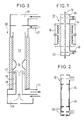
- Figure 1 shows a technique reactor used for the formation of such a coating hermetic.
- a fiber 10 descends vertically in a reactor 12 of cylindrical shape, at a inlet 14 from which a reactive gas mixture enters.
- This reactive gas mixture which may for example be consisting of ethylene and trichloromethane, can be advantageously made of acetylene, in the presence of a inert gaseous vehicle.
- the gas mixture is discharged through an outlet 16 placed at the bottom of the reactor 12. Given the flow rates used, the gas circulates in the reactor with laminar flow.
- Maintaining the gaseous medium at a temperature suitable for chemical vapor deposition is provided by a heating device 18.
- the penetration of the outside atmosphere in the reactor is prevented by formation of two airlocks 20 and 22 at entry and exit of the reactor respectively.
- FIG. 2 represents, in very schematic form, carbon soot deposits observed in a reactor of the type shown in Figure 1, after manufacture of an optical fiber.
- the soot has also tend to settle on partitions transverse, including airlocks, as indicated by the reference 28.
- fouling of the reactor i.e. the thickness of the soot deposit becomes excessive, it must stop the fiber drawing to clean or replace the reactor.
- FIG. 3 is a schematic section of an apparatus according to the invention.
- This includes a reactor body 30 which comprises a first part substantially cylindrical 32, a second part 34 forming a narrowing, and a third part 36 which contains a central longitudinal sleeve 38 which opens at a internal end or opening 40 near the narrowing of the second part 34 of the reactor.
- the medium gaseous reagent is introduced through an inlet 42 placed at the upper part of the reactor and is evacuated with soot at the bottom by an exit 44.
- Airlocks 46 and 48 protect the reactive gas medium against the action of the outside atmosphere.
- the structure of the reactor in Figure 3 presents several differences from the reactor of the prior art, as shown in Figure 1.
- the most important difference is the narrowing of the second part 34. It is not necessary that this second part 34 has great length but it is advantageous that the narrowing is gradual so that the reactive gaseous medium which descends from the first part 32 accelerates and prevents gas from rising inert introduced by the sleeve 38 towards this first part 32.
- the main chemical deposition reaction in vapor phase which forms the hermetic coating on the fiber is made in the first part 32.
- the reactive gaseous medium and the soot that it can contain, formed by chemical phase deposition vapor are evacuated with the inert gas introduced by the sleeve 38, through the annular space formed between the wall of the third part 36 of the reactor and the sleeve 38.
- the causes soot particles to settle in this third part of the reactor has little importance since the fiber is protected by the inert gas of inside the sleeve and is no longer in contact with soot.
- Another important feature of the invention is the presence of the sleeve which opens near the second part 34, that is to say that its opening 40 is at a distance from the second part 34 which is of the order of size of the distance separating the sleeve 38 from the wall of the reactor in the third part 36.
- This arrangement is intended to create, between shrinking and the open end 40 of the sleeve, a flow regime such that the inert gas introduced by the sleeve does not rise not beyond the narrowing of the second part 34, but ensures the soot training after changing flow direction outside the sleeve.
- the gas flow regime at the second part 34 of the reactor and the end 40 of the sleeve is particularly important for this purpose.
- the first part 32 and the third part 36 have an internal diameter of 34 mm, and the second part 34 has a smaller section whose diameter is 25 mm.
- the sleeve 40 has a section circular 19 mm in diameter. The end 40 is at a 23 mm distance from the smallest section the second part 34 of the reactor.
- the reactive gaseous medium introduced by inlet 42 is formed from a mixture of acetylene and argon transmitted with a flow rate of 0.5 l / min.
- Argon gas is transmitted by airlock 48 with a flow rate of 2 l / min in the sleeve 38. So although the speed of the gas against the current fiber inside the sleeve 38 is very greater than the speed of the reactive gaseous medium which goes down in the first part 32 in the same direction as the fiber, the shrinking of the second part 34 accelerates the gaseous reactive medium which is driven out by the inert gas in the annular space surrounding the sleeve 38, with a speed of circulation in space ring finger six to seven times larger than in the first part 32.
- the fiber length that can be obtained before stopping an operation by fouling the reactor is around 2.5 times the length obtained in the absence of the sleeve 38 and of the constriction 34.
- the reactor according to the invention draws also advantage of the improvements known in the technique for this kind of reactor, concerning in particular the material forming the walls of the reactor, the state of surface of this material, etc.
- the temperature conditions prevailing in the reactor also correspond to the best known conditions of the skilled person.
Landscapes
- Life Sciences & Earth Sciences (AREA)
- Chemical & Material Sciences (AREA)
- General Life Sciences & Earth Sciences (AREA)
- Engineering & Computer Science (AREA)
- Chemical Kinetics & Catalysis (AREA)
- General Chemical & Material Sciences (AREA)
- Geochemistry & Mineralogy (AREA)
- Materials Engineering (AREA)
- Organic Chemistry (AREA)
- Surface Treatment Of Glass Fibres Or Filaments (AREA)
Description
La présente invention concerne un procédé de fabrication de fibres optiques ayant un revêtement hermétique, ainsi qu'un appareil convenant à la mise en oeuvre d'un tel procédé.The present invention relates to a manufacturing process optical fibers having a hermetic coating, as well as an apparatus suitable for the implementation of a such process.
On sait déjà utiliser des gaz organiques pour la formation de revêtements hermétiques sur des fibres optiques, par exemple formées de silice, à partir de compositions à base de carbone. Ainsi, la demande de brevet européen EP-A-308 143 décrit une fibre optique revêtue d'un revêtement hermétique de carbone lors de son passage dans un réacteur dans lequel la fibre est mise au contact d'un milieu gazeux réactif. Cet appareil comprend essentiellement un réacteur cylindrique placé verticalement, et la fibre descend dans ce réacteur. Un milieu gazeux réactif est introduit à la partie inférieure du réacteur et s'échappe à sa partie supérieure. Des sas sont formés aux extrémités du réacteur pour empêcher l'interaction entre l'atmosphère et le milieu gazeux réactif.We already know how to use organic gases for the forming hermetic coatings on fibers optics, for example formed of silica, from carbon-based compositions. So the request for European patent EP-A-308 143 describes an optical fiber coated with an airtight carbon coating when passage in a reactor in which the fiber is put in contact with a reactive gaseous medium. This device includes basically a cylindrical reactor placed vertically, and the fiber descends into this reactor. A reactive gas medium is introduced at the bottom from the reactor and escapes at its upper part. Airlocks are formed at the ends of the reactor to prevent the interaction between the atmosphere and the gaseous medium reagent.
On s'est rendu compte que ces appareils présentaient rapidement un encrassement par dépôt de suies de carbone aux parties supérieure et surtout inférieure de l'appareil. La présence de suies dans le réacteur permet leur fixation sur la fibre et la détérioration des propriétés du revêtement hermétique déjà formé. En conséquence, la longueur maximale de fibre qui peut être obtenue avant que l'appareil ne doive subir un nettoyage est seulement de quelques kilomètres.We realized that these devices had quickly fouling by depositing carbon soot at the upper and especially lower parts of the device. The presence of soot in the reactor allows their fixation on the fiber and the deterioration of properties of the hermetic coating already formed. In consequence, the maximum fiber length that can be obtained before the device must be cleaned is only a few kilometers.
Etant donné que le coût des fibres optiques réalisées dépend directement de la longueur de fibre qui peut être fabriquée en une seule fois par traitement dans un tel appareil, on a essayé de réduire cet encrassement.Since the cost of optical fibers performed depends directly on the fiber length which can be made all at once by treatment in such an apparatus, we have tried to reduce this fouling.
Le document EP-A-518 318 décrit un procédé et un appareil de fabrication d'une fibre optique ayant un revêtement hermétique selon lesquels l'encrassement du réacteur est évité par formation d'un film continu de liquide à la paroi interne du réacteur ; le liquide, en s'écoulant, entraíne les suies qui peuvent se former dans le réacteur. Il est indiqué que ce procédé et cet appareil permettent l'obtention de fibres continues de longueur supérieure à 100 km. Cependant, ce procédé est complexe et délicat à mettre en oeuvre, et la formation d'un film liquide continu le long des parois présente des difficultés. Le réacteur a une configuration qui s'évase vers le bas et comporte des dispositifs d'épuration du liquide utilisé et des gaz usés. Dans ce réacteur, le milieu gazeux réactif circule à vitesse constante dans le même sens que la fibre, puis la vitesse diminue au niveau d'un embout dont l'extrémité correspond à un élargissement du réacteur.The document EP-A-518 318 describes a method and a apparatus for manufacturing an optical fiber having a hermetic coating according to which the fouling of the reactor is avoided by forming a continuous film of liquid at the inner wall of the reactor; the liquid, in flowing, causes soot that can form in the reactor. It is stated that this process and this device allow the production of continuous fibers of length greater than 100 km. However, this process is complex and delicate to implement, and the formation of a film continuous liquid along the walls has difficulties. The reactor has a flaring configuration downwards and has devices for purifying the liquid used and waste gases. In this reactor, the reactive gaseous medium circulates at constant speed in the same direction as the fiber, then the speed decreases at the level a tip whose end corresponds to a widening of the reactor.
Le document EP-A-571 915 décrit un autre appareil de production d'une fibre optique ayant un revêtement hermétique et pouvant avoir une grande longueur grâce à la réduction de l'encrassement du réacteur. Selon ce document, la vitesse de déplacement du milieu réactif gazeux est réduite progressivement le long de la fibre, dans la partie dans laquelle est réalisé le dépôt chimique en phase vapeur. Ce document décrit notamment une comparaison effectuée entre un réacteur classique et un réacteur dont la section augmente progressivement, ce réacteur permettant la fabrication d'une fibre deux fois plus longue qu'avec le premier réacteur.The document EP-A-571 915 describes another apparatus for production of an optical fiber having a hermetic coating and can be very long thanks to the reduction of reactor fouling. According to what document, the speed of movement of the reactive medium gas is gradually reduced along the fiber, in the part in which the chemical deposition is carried out in vapor phase. This document describes in particular a comparison made between a conventional reactor and a reactor whose section gradually increases, this reactor allowing the fabrication of a fiber twice longer than with the first reactor.
Le problème précité de l'encrassement du réacteur est dû au fait qu'une partie du milieu gazeux réactif se décompose en formant des suies qui se déposent sur la paroi du réacteur. Dans le document précité EP-A-518 318, le résultat est obtenu par entraínement mécanique des suies au fur et à mesure de leur formation, alors que, dans le document précité EP-A-571 915, le résultat est obtenu par réduction de la vitesse du courant de gaz de manière que les suies soient maintenues à distance des parois du réacteur, avec réduction de la vitesse de déplacement. The aforementioned problem of reactor fouling is due to the fact that part of the reactive gaseous medium decomposes by forming soot which is deposited on the reactor wall. In the aforementioned document EP-A-518,318, the result is obtained by mechanical drive of soot as it forms, while, in the aforementioned document EP-A-571 915, the result is obtained by reducing the speed of the gas stream from so that the soot is kept away from reactor walls, with speed reduction displacement.
L'invention concerne une autre solution au problème de l'encrassement qui permet une augmentation considérable de la longueur de fibre qui peut être fabriquée dans un réacteur. Plus précisément, selon l'invention, à l'emplacement auquel la fibre a pratiquement terminé de recevoir le revêtement hermétique de carbone, le milieu gazeux réactif est accéléré avant d'être écarté de la fibre qui pénètre alors directement dans un gaz inerte. L'encrassement est réduit dans la partie de dépôt chimique en phase vapeur parce que le courant de gaz est accéléré, et les suies sont ensuite entraínées dans un espace annulaire séparé de la fibre et ne peuvent donc pas se déposer sur la fibre.The invention relates to another solution to the problem. fouling which allows a considerable increase the length of fiber that can be made in one reactor. More specifically, according to the invention, the location at which the fiber has practically finished receive the hermetic carbon coating, the medium reactive gas is accelerated before being removed from the fiber which then penetrates directly into an inert gas. The fouling is reduced in the chemical deposition part in the vapor phase because the gas flow is accelerated, and the soot is then entrained in a space annular separate from the fiber and therefore cannot deposit on the fiber.
Ainsi, l'invention concerne un procédé de fabrication d'une fibre optique revêtue, du type qui comprend la fabrication d'une fibre à partir d'une préforme de verre chauffée et la mise en contact de la fibre avec un milieu gazeux réactif destiné à former un revêtement sur la fibre par dépôt chimique en phase vapeur, le procédé comprenant la circulation de la fibre dans ledit milieu gazeux réactif, qui circule à une vitesse constante dans le sens de déplacement de la fibre et au moins sur une partie du parcours de ladite fibre dans ledit milieu réactif, et la circulation de la fibre dans un gaz inerte circulant en sens opposé au sens de circulation de la fibre après le dépôt du revêtement ; selon l'invention, le procédé comprend, dans la partie finale du parcours de la fibre dans ledit milieu gazeux réactif, l'accélération dudit milieu gazeux réactif dans le sens de déplacement de la fibre, et l'évacuation dudit milieu gazeux réactif et du gaz inerte après la rencontre du courant du milieu gazeux réactif et du courant de gaz inerte, à distance de la fibre, pour l'entraínement des suies formées.Thus, the invention relates to a method of manufacture of a coated optical fiber, of the type which includes making a fiber from a heated glass preform and bringing the fiber with a reactive gaseous medium intended to form a coating on the fiber by chemical phase deposition steam, the process including circulation of the fiber in said reactive gaseous medium, which circulates at a constant speed in the direction of fiber travel and at least on part of the course of said fiber in said reactive medium, and the circulation of the fiber in an inert gas flowing in the opposite direction to the direction of fiber circulation after coating is deposited; according to the invention, the method comprises, in the part end of the fiber path in said gaseous medium reactive, the acceleration of said reactive gaseous medium in the direction of movement of the fiber, and the evacuation of said fiber reactive gas medium and inert gas after the encounter of the reactive gas medium current and of the gas current inert, away from the fiber, for driving soot formed.
De préférence, l'accélération du milieu gazeux réactif donne à celui-ci, au niveau de la fibre, une vitesse au moins supérieure de 50 % à la vitesse constante de circulation dudit milieu gazeux réactif qui circule dans le même sens que la fibre.Preferably, the acceleration of the gaseous medium reagent gives it, at the fiber level, a speed at least 50% faster than constant speed of circulation of said reactive gaseous medium which circulates in the same direction as the fiber.
De préférence, l'accélération du milieu gazeux réactif est effectuée à un emplacement auquel la température de surface de la fibre est comprise entre 1 000 et 1 050 °C.Preferably, the acceleration of the gaseous medium reagent is performed at a location where the fiber surface temperature is between 1,000 and 1,050 ° C.
Dans un exemple de réalisation, le milieu gazeux réactif contient de l'acétylène, et le gaz inerte est de l'argon.In an exemplary embodiment, the gaseous medium reagent contains acetylene, and the inert gas is argon.
L'invention concerne aussi un appareil de fabrication d'une fibre optique munie d'un revêtement hermétique, dans lequel une préforme de verre destinée à une fibre optique est fondue dans un four de fibrage pour la production d'une fibre optique nue qui passe longitudinalement dans un réacteur dans lequel un milieu gazeux réactif est transmis et la fibre optique nue est revêtue d'un mince revêtement de carbone formé par le milieu gazeux réactif par dépôt chimique en phase vapeur ; selon l'invention, le réacteur comporte une première partie dans laquelle est effectuée une opération de dépôt chimique en phase vapeur qui forme un revêtement hermétique, une seconde partie de section inférieure à celle de la première partie, et une troisième partie munie intérieurement d'un manchon, ledit manchon étant disposé longitudinalement, ayant une extrémité ouverte du côté de la seconde partie et délimitant un espace annulaire entre lui-même et la troisième partie, l'autre extrémité du manchon étant raccordée à un dispositif d'introduction d'un gaz inerte.The invention also relates to an apparatus for manufacture of an optical fiber provided with a coating hermetic, in which a glass preform intended for an optical fiber is melted in a fiber-drawing oven to the production of a bare optical fiber that passes longitudinally in a reactor in which a medium reactive gas is transmitted and the bare optical fiber is coated with a thin coating of carbon formed by the reactive gas medium by chemical vapor deposition; according to the invention, the reactor comprises a first part in which a deposit operation is carried out chemical vapor phase that forms a coating hermetic, a second section of section less than that of the first part, and a third part provided internally of a sleeve, said sleeve being disposed longitudinally, having one end open on the side of the second part and delimiting an annular space between himself and the third part, the other end of the sleeve being connected to an introducer of an inert gas.
De préférence, la distance longitudinale comprise entre l'extrémité du manchon et la seconde partie du réacteur est de l'ordre de grandeur de la distance radiale séparant le manchon de la troisième partie.Preferably, the longitudinal distance included between the end of the sleeve and the second part of the reactor is of the order of magnitude of the radial distance separating the sleeve from the third part.
Il est avantageux que la seconde partie comporte un rétrécissement progressif destiné à éviter la création de turbulences dans le courant du milieu gazeux réactif circulant dans la seconde partie. It is advantageous that the second part includes a gradual narrowing to prevent the creation of turbulence in the flow of the reactive gas medium circulating in the second part.
De préférence, la première partie a une forme cylindrique, et il est aussi avantageux que le manchon et la troisième partie aient aussi une forme cylindrique.Preferably, the first part has a cylindrical shape, and it is as advantageous as the sleeve and the third part also have a cylindrical shape.
De préférence, l'appareil comporte en outre, à chaque extrémité du réacteur, un sas d'introduction d'un gaz inerte destiné à empêcher l'entrée de l'atmosphère ambiante. Il est alors avantageux que le sas d'introduction d'un gaz inerte placé du côté de sortie de fibre du réacteur constitue aussi le dispositif d'introduction d'un gaz inerte.Preferably, the apparatus further comprises, at at each end of the reactor, an airlock for the introduction of a inert gas intended to prevent entry of the atmosphere ambient. It is therefore advantageous for the airlock introduction of an inert gas placed on the outlet side of reactor fiber also constitutes the device introduction of an inert gas.
D'autres caractéristiques et avantages de
l'invention ressortiront mieux de la description qui va
suivre d'un exemple de réalisation, faite en référence au
dessin annexé sur lequel :
Dans le procédé classique de fabrication de fibre optique, une fibre nue provenant du fibrage d'une préforme reçoit un revêtement essentiellement formé de carbone par dépôt chimique en phase vapeur. Ce revêtement est hermétique et assure ainsi la protection de la fibre pendant de longues périodes. Pour que ce revêtement soit hermétique, il faut que soient remplies un certain nombre de conditions relatives notamment à la composition du milieu réactif gazeux utilisé pour le dépôt chimique en phase vapeur et aux températures de réaction. L'opération de décomposition qui accompagne ce dépôt chimique en phase vapeur crée des suies de carbone qui ont tendance à se déposer non seulement dans le réacteur, mais aussi sur la fibre elle-même. Ce dépôt non hermétique de suies est d'autant plus nuisible qu'il est important, et il peut même rendre la fibre inutilisable. En conséquence, il est essentiel de limiter la quantité de suies pouvant se déposer sur le revêtement hermétique formé dans l'étape initiale de dépôt chimique en phase vapeur.In the conventional fiber manufacturing process optical, a bare fiber from the fiber of a preform receives an essentially carbon coating by chemical vapor deposition. This coating is hermetic and thus ensures the protection of the fiber for long periods. So that this coating is hermetic, a certain number must be met conditions relating in particular to the composition of the gaseous reactive medium used for chemical deposition in vapor phase and at reaction temperatures. The operation of decomposition which accompanies this chemical deposit in phase vapor creates carbon soot which tends to deposit not only in the reactor but also on the fiber itself. This non-hermetic deposit of soot is all the more harmful as it is important, and it can even make the fiber unusable. As a result, it is essential to limit the amount of soot that can deposit on the airtight coating formed in step initial chemical vapor deposition.
La figure 1 représente un réacteur de la technique
antérieure utilisé pour la formation d'un tel revêtement
hermétique. Dans ce réacteur, une fibre 10 descend verticalement
dans un réacteur 12 de forme cylindrique, à une
entrée 14 duquel pénètre un mélange gazeux réactif. Ce
mélange gazeux réactif, qui peut être par exemple
constitué d'éthylène et de trichlorométhane, peut être
avantageusement constitué d'acétylène, en présence d'un
véhicule gazeux inerte. Après réaction, le mélange gazeux
est évacué par une sortie 16 placée au bas du réacteur 12.
Compte tenu des débits utilisés, le gaz circule dans le
réacteur avec un écoulement laminaire.Figure 1 shows a technique reactor
used for the formation of such a coating
hermetic. In this reactor, a
Le maintien du milieu gazeux à une température
convenant au dépôt chimique en phase vapeur est assuré par
un dispositif de chauffage 18. En outre, la pénétration de
l'atmosphère extérieure dans le réacteur est empêchée par
formation de deux sas 20 et 22 à l'entrée et à la sortie
du réacteur respectivement.Maintaining the gaseous medium at a temperature
suitable for chemical vapor deposition is provided by
a
La figure 2 représente, sous forme très schématique,
des dépôts de suies de carbone observés dans un réacteur
du type représenté sur la figure 1, après la fabrication
d'une fibre optique. On observe un intense dépôt 24 de
suies à la partie supérieure et un dépôt 26 encore plus
intense à la partie inférieure du réacteur. Les suies ont
aussi tendance à se déposer sur les cloisons
transversales, notamment des sas, comme indiqué par la
référence 28. Lorsque l'encrassement du réacteur, c'est-à-dire
l'épaisseur de dépôt de suies, devient excessif, il
faut interrompre le fibrage de la fibre pour nettoyer ou
remplacer le réacteur.FIG. 2 represents, in very schematic form,
carbon soot deposits observed in a reactor
of the type shown in Figure 1, after manufacture
of an optical fiber. There is an
La figure 3 est une coupe schématique d'un appareil
selon l'invention. Celui-ci comporte un corps de réacteur
30 qui comprend une première partie sensiblement
cylindrique 32, une seconde partie 34 formant un
rétrécissement, et une troisième partie 36 qui contient un
manchon longitudinal central 38 qui débouche à une
extrémité interne ou ouverture 40 à proximité du
rétrécissement de la seconde partie 34 du réacteur. Comme
dans le réacteur de la technique antérieure, le milieu
réactif gazeux est introduit par une entrée 42 placée à la
partie supérieure du réacteur et est évacué avec les suies
à la partie inférieure par une sortie 44. Des sas 46 et 48
protègent le milieu gazeux réactif contre l'action de
l'atmosphère extérieure.Figure 3 is a schematic section of an apparatus
according to the invention. This includes a
La structure du réacteur de la figure 3 présente
plusieurs différences par rapport au réacteur de la
technique antérieure, tel que représenté sur la figure 1.
La différence la plus importante est le rétrécissement de
la seconde partie 34. Il n'est pas nécessaire que cette
seconde partie 34 ait une grande longueur, mais il est
avantageux que le rétrécissement soit progressif afin que
le milieu gazeux réactif qui descend de la première partie
32 subisse une accélération et empêche la remontée du gaz
inerte introduit par le manchon 38 vers cette première
partie 32. La réaction principale de dépôt chimique en
phase vapeur qui forme le revêtement hermétique sur la
fibre s'effectue dans la première partie 32. Une fibre qui
arrive dans la seconde partie 34 a une température de
l'ordre de 1 000 à 1 050 °C, c'est-à-dire une température
à laquelle la génération de suies devient prépondérante
vis-à-vis du dépôt hétérogène sur fibre.The structure of the reactor in Figure 3 presents
several differences from the reactor of the
prior art, as shown in Figure 1.
The most important difference is the narrowing of
the
A ce moment, le milieu gazeux réactif et les suies
qu'il peut contenir, formées par dépôt chimique en phase
vapeur, sont évacués avec le gaz inerte introduit par le
manchon 38, par l'espace annulaire formé entre la paroi de
la troisième partie 36 du réacteur et le manchon 38. Le
fait que des particules de suies puissent se déposer dans
cette troisième partie du réacteur a peu d'importance
puisque la fibre est protégée par le gaz inerte de
l'intérieur du manchon et n'est plus au contact des suies.At this time, the reactive gaseous medium and the soot
that it can contain, formed by chemical phase deposition
vapor, are evacuated with the inert gas introduced by the
Une autre caractéristique importante de l'invention
est la présence du manchon qui débouche à proximité de la
seconde partie 34, c'est-à-dire que son ouverture 40 est à
une distance de la seconde partie 34 qui est de l'ordre de
grandeur de la distance séparant le manchon 38 de la paroi
du réacteur dans la troisième partie 36. Cette disposition
est destinée à créer, entre le rétrécissement et
l'extrémité ouverte 40 du manchon, un régime d'écoulement
tel que le gaz inerte introduit par le manchon ne remonte
pas au-delà du rétrécissement de la seconde partie 34,
mais assure l'entraínement des suies après avoir changé de
direction par écoulement à l'extérieur du manchon. Le
régime d'écoulement des gaz au niveau de la seconde partie
34 du réacteur et de l'extrémité 40 du manchon est
particulièrement important à cet effet. Pour que le gaz
inerte introduit par le manchon 38 ne puisse pas remonter
dans la première partie 32 et, d'autre part, pour que le
milieu réactif gazeux qui a réagi et qui contient des
suies soit évacué par la partie annulaire formée entre le
manchon et la troisième partie 36 du réacteur, il faut que
les débits du milieu réactif gazeux transmis par l'entrée
42 et du gaz inerte transmis par le manchon soient
équilibrés en fonction des sections du rétrécissement de
la seconde partie 34, du manchon 38 et de l'espace
annulaire compris entre le manchon 38 et la troisième
partie 36.Another important feature of the invention
is the presence of the sleeve which opens near the
Dans un exemple de réacteur dans lequel ce dernier
et le manchon ont une symétrie de révolution autour d'un
axe central suivi par la fibre, la première partie 32 et
la troisième partie 36 ont un diamètre interne de 34 mm,
et la seconde partie 34 a une plus petite section dont le
diamètre est de 25 mm. Le manchon 40 a une section
circulaire de 19 mm de diamètre. L'extrémité 40 est à une
distance de 23 mm de la partie de plus petite section de
la seconde partie 34 du réacteur.In an example of a reactor in which the latter
and the sleeve have a symmetry of revolution around a
central axis followed by the fiber, the
Dans ce cas, le milieu gazeux réactif introduit par
l'entrée 42 est formé d'un mélange d'acétylène et d'argon
transmis avec un débit de 0,5 l/min. De l'argon gazeux est
transmis par le sas 48 avec un débit de 2 l/min dans le
manchon 38. Ainsi, bien que la vitesse du gaz à contre-courant
de la fibre à l'intérieur du manchon 38 soit très
supérieure à la vitesse du milieu gazeux réactif qui
descend dans la première partie 32 dans le même sens que
la fibre, le rétrécissement de la seconde partie 34
accélère le milieu réactif gazeux qui est chassé par le
gaz inerte dans l'espace annulaire entourant le manchon
38, avec une vitesse de circulation dans l'espace
annulaire six à sept fois plus grande que dans la première
partie 32.In this case, the reactive gaseous medium introduced by
Avec les valeurs indiquées dans l'exemple précédent,
on constate que la longueur de fibre qui peut être obtenue
avant arrêt d'une opération par encrassement du réacteur
est de l'ordre de 2,5 fois la longueur obtenue en
l'absence du manchon 38 et du rétrécissement 34.With the values shown in the previous example,
we see that the fiber length that can be obtained
before stopping an operation by fouling the reactor
is around 2.5 times the length obtained in
the absence of the
Bien qu'on puisse obtenir une certaine amélioration
lorsque l'extrémité 40 du manchon 38 est plus éloignée de
la seconde partie rétrécie 34, on a constaté qu'il était
préférable que cette extrémité 40 soit proche de cette
seconde partie 34, sans cependant provoquer un rétrécissement
excessif entre l'extrémité 40 du manchon et le
réacteur. En l'absence du rétrécissement de la seconde
partie 34, le manchon 38 ne donne pas d'amélioration très
significative puisqu'il a pour seul effet de réduire la
longueur efficace du réacteur 30.Although we can get some improvement
when the
Bien entendu, le réacteur selon l'invention tire aussi avantage des perfectionnements connus dans la technique pour ce genre de réacteur, concernant notamment le matériau formant les parois du réacteur, l'état de surface de ce matériau, etc. En outre, il est bien entendu que les conditions de température régnant dans le réacteur correspondent aussi aux meilleures conditions connues de l'homme du métier.Of course, the reactor according to the invention draws also advantage of the improvements known in the technique for this kind of reactor, concerning in particular the material forming the walls of the reactor, the state of surface of this material, etc. In addition, it is understood that the temperature conditions prevailing in the reactor also correspond to the best known conditions of the skilled person.
Il est bien entendu que l'invention n'a été décrite et représentée qu'à titre d'exemple préférentiel et qu'on pourra apporter toute équivalence technique dans ses éléments constitutifs sans pour autant sortir de son cadre.It is understood that the invention has not been described and shown only as a preferred example and that may provide any technical equivalence in its constituent elements without departing from its frame.
Claims (10)
- A method of manufacturing a coated optical fiber, the method being of the type comprising manufacturing a fiber from a heated glass preform, and putting the fiber in contact with a reactive gaseous medium serving to form a coating on the fiber by chemical vapor deposition, the method further comprising causing the fiber to advance through a reactive gas medium which flows at a constant speed in the direction of advance of the fiber, and over at least a portion of the path of said fiber through said reactive medium, and causing the fiber to advance through an inert gas flowing in the opposite direction from the direction of advance of the fiber after the coating has been deposited;said method being characterized in that the method further comprises accelerating the gaseous medium in the direction of advance of the fiber in the final portion of the path of the fiber through said reactive gaseous medium; andremoving the reactive gaseous medium and the inert gas after the gaseous medium stream meets the inert gas stream, so as to entrain the soot that has formed, removal taking place remote from the fiber.
- A method according to claim 1, characterized in that accelerating said reactive gaseous medium imparts a speed to it at the fiber that is at least 50% higher than the constant speed of flow of the reactive gaseous medium flowing in the same direction as the fiber.
- A method according to claim 1 or 2, characterized in that the reactive gaseous medium is accelerated at a place where the surface temperature of the fiber lies in the range 1000°C to 1050°C.
- A method according to any preceding claim, characterized in that the reactive gaseous medium contains acetylene, and the inert gas is argon.
- Apparatus for manufacturing an optical fiber provided with a hermetic coating, in which apparatus a glass optical fiber preform is melted in a fiberdrawing furnace to produce a bare optical fiber which passes longitudinally through a reactor (30) through which a reactive gaseous medium is passed, and the bare optical fiber is coated with a thin carbon coating formed by the reactive gaseous medium by chemical vapor deposition, said apparatus being characterized in that the reactor (30) comprises:a first portion (32) in which a chemical vapor deposition step is performed to form a hermetic coating;a second portion (34) of cross-sectional area smaller than that of the first portion; anda third portion (36) provided internally with a sleeve (38), the sleeve (38) being disposed longitudinally, having an open end (40) in the vicinity of the second portion, and defining an annular space between itself and the third portion (36), the other end of the sleeve being connected to a device for feeding in an inert gas.
- Apparatus according to claim 5, characterized in that the longitudinal distance between the end (40) of the sleeve (38) and the second portion (34) is of the same order of magnitude as the radial distance between the sleeve (38) and the third portion (36).
- Apparatus according to claim 5 or 6, characterized in that the second portion (34) is provided with a gradually tapering neck designed to avoid turbulence being set up in the reactive gaseous medium stream flowing through the second portion (34).
- Apparatus according to any one of claims 5 to 7, characterized in that the first portion (32), the sleeve (38), and the third portion (36) are cylindrical in shape.
- Apparatus according to any one of claims 5 to 8, characterized in that, at each end of the reactor, the apparatus further comprises an air lock (46, 48) via which an inert gas can be fed in, and which serves to prevent the ambient atmosphere from entering the reactor.
- Apparatus according to claim 9, characterized in that the inert gas feed air lock (48) that is placed at the fiber outlet of the reactor (30) constitutes the device for feeding in an inert gas.
Applications Claiming Priority (2)
| Application Number | Priority Date | Filing Date | Title |
|---|---|---|---|
| FR9704542 | 1997-04-14 | ||
| FR9704542A FR2761979B1 (en) | 1997-04-14 | 1997-04-14 | METHOD AND APPARATUS FOR MANUFACTURING AN OPTICAL FIBER PROVIDED WITH A HERMETIC COATING |
Publications (2)
| Publication Number | Publication Date |
|---|---|
| EP0872459A1 EP0872459A1 (en) | 1998-10-21 |
| EP0872459B1 true EP0872459B1 (en) | 2001-10-04 |
Family
ID=9505854
Family Applications (1)
| Application Number | Title | Priority Date | Filing Date |
|---|---|---|---|
| EP98400864A Expired - Lifetime EP0872459B1 (en) | 1997-04-14 | 1998-04-09 | Method and apparatus for the manufacture of an optical fibre with a hermetic coating |
Country Status (5)
| Country | Link |
|---|---|
| US (1) | US6029476A (en) |
| EP (1) | EP0872459B1 (en) |
| DE (1) | DE69801859T2 (en) |
| DK (1) | DK0872459T3 (en) |
| FR (1) | FR2761979B1 (en) |
Families Citing this family (5)
| Publication number | Priority date | Publication date | Assignee | Title |
|---|---|---|---|---|
| US6715323B1 (en) * | 1997-11-21 | 2004-04-06 | Pirelli Cavi E Sistemi S.P.A. | Method and apparatus for cooling optical fibers |
| US6489376B1 (en) | 2000-07-31 | 2002-12-03 | Alcatel | Formulation of UV-curable coatings for optical fiber for a fast cure |
| NO316775B1 (en) * | 2001-06-11 | 2004-05-03 | Optoplan As | Method of Coating a Fiber with Fiber Optic Bragg Grids (FBG) |
| KR100545814B1 (en) * | 2002-08-31 | 2006-01-24 | 엘에스전선 주식회사 | Optical Fiber Edge Melting Furnace and Optical Fiber Edge Cutting Method Using The Same |
| EP2138471A1 (en) | 2008-06-25 | 2009-12-30 | Acreo AB | Atomic layer deposition of hydrogen barrier coatings on optical fibers |
Family Cites Families (11)
| Publication number | Priority date | Publication date | Assignee | Title |
|---|---|---|---|---|
| JPH02145462A (en) * | 1988-11-28 | 1990-06-04 | Sumitomo Electric Ind Ltd | Production of hermetic coat fiber |
| AU624203B2 (en) * | 1988-12-21 | 1992-06-04 | Sumitomo Electric Industries, Ltd. | Method and apparatus for producing coated optical fiber |
| JPH02192438A (en) * | 1989-01-19 | 1990-07-30 | Furukawa Electric Co Ltd:The | Hermetically coated optical fiber producing furnace |
| JP2798486B2 (en) * | 1990-08-01 | 1998-09-17 | 住友電気工業株式会社 | Method and apparatus for producing hermetic coated optical fiber |
| US5152817A (en) * | 1991-01-15 | 1992-10-06 | Corning Incorporated | Reactor for coating optical fibers |
| AU651863B2 (en) * | 1991-02-14 | 1994-08-04 | Nippon Telegraph & Telephone Corporation | Method for manufacturing a hermetically coated optical fiber |
| JPH05124841A (en) * | 1991-06-12 | 1993-05-21 | Sumitomo Electric Ind Ltd | Production of hermetically coated optical fiber |
| JP2785635B2 (en) * | 1992-05-26 | 1998-08-13 | 住友電気工業株式会社 | Hermetic coated optical fiber manufacturing equipment |
| US5346520A (en) * | 1992-09-23 | 1994-09-13 | Corning Incorporated | Apparatus for applying a carbon coating to optical fibers |
| KR0165004B1 (en) * | 1993-07-13 | 1999-01-15 | . | Optical fiber drawing furnace and drawing method |
| JP3316290B2 (en) * | 1994-01-18 | 2002-08-19 | 古河電気工業株式会社 | Method for producing hermetic coated optical fiber |
-
1997
- 1997-04-14 FR FR9704542A patent/FR2761979B1/en not_active Expired - Fee Related
-
1998
- 1998-04-09 DE DE69801859T patent/DE69801859T2/en not_active Expired - Fee Related
- 1998-04-09 DK DK98400864T patent/DK0872459T3/en active
- 1998-04-09 EP EP98400864A patent/EP0872459B1/en not_active Expired - Lifetime
- 1998-04-13 US US09/058,774 patent/US6029476A/en not_active Expired - Fee Related
Also Published As
| Publication number | Publication date |
|---|---|
| DE69801859D1 (en) | 2001-11-08 |
| US6029476A (en) | 2000-02-29 |
| DE69801859T2 (en) | 2002-05-02 |
| FR2761979A1 (en) | 1998-10-16 |
| FR2761979B1 (en) | 1999-05-28 |
| EP0872459A1 (en) | 1998-10-21 |
| DK0872459T3 (en) | 2002-01-21 |
Similar Documents
| Publication | Publication Date | Title |
|---|---|---|
| EP0054495B2 (en) | Optical waveguide with a fluor-doped core | |
| EP0875489B1 (en) | Process and apparatus for producing preforms for glass fibres | |
| FR2725441A1 (en) | OPTICAL FIBER PREFORM AND MANUFACTURING METHOD THEREOF | |
| EP3068725B1 (en) | Method for continuous, travelling production of nanostructures aligned on a substrate and related device | |
| EP0273812B1 (en) | Process and apparatus for making a glass yarn obtained directly under the bushing | |
| EP0112222B1 (en) | Device for producing a toroidal-shaped article starting from a pliable material | |
| CH634027A5 (en) | METHOD AND DEVICE FOR FIBRATION OF GLASS. | |
| FR2636078A1 (en) | METHOD AND APPARATUS OF CHEMICAL VAPOR DEPOSITION COATING FOR THE PRODUCTION OF LAYERS ON SUBSTRATES | |
| EP0511044A1 (en) | Deposition of pyrolyzed layers with improved performance and a glass pane coated with such a layer | |
| EP0727392B1 (en) | Method for treating the surface of a preform, method for realising a preform using the said method and preform made by the said methods | |
| EP0693865B1 (en) | Induction plasma torch | |
| CH687203A5 (en) | Apparatus and method for forming a coating by pyrolysis. | |
| FR2531947A1 (en) | PROCESS FOR MANUFACTURING OPTICAL WAVEGUIDES IN FIBERGLASS | |
| FR2595684A1 (en) | METHOD OF LUBRICATING A MOLD FOR MANUFACTURING A GLASS CONTAINER | |
| EP0872459B1 (en) | Method and apparatus for the manufacture of an optical fibre with a hermetic coating | |
| EP0250326A1 (en) | Method for making preforms for optical fibres | |
| FR2496087A1 (en) | PROCESS AND APPARATUS FOR MANUFACTURING POROUS LAMPS OF OPTICAL FIBERS | |
| FR2621909A1 (en) | ||
| FR2609708A1 (en) | Device for the manufacture of fibres from a molten inorganic mass | |
| EP0251912A1 (en) | Process for the metallically tight coating of a glass fibre, and device for carrying out this method | |
| FR2488872A1 (en) | PROCESS FOR PRODUCING SINGLE-SHAPED BASE MATERIAL FOR OPTICAL TRANSMISSION FIBER | |
| WO1989002876A1 (en) | Method for fabricating optical fibres with preform obtained by sinking | |
| FR2575151A1 (en) | Process and device for the manufacture of preforms for optical fibres, and preforms obtained by this process | |
| EP0981502A1 (en) | Method for depositing a coating layer on an optical fibre while it is being drawn and device for its implementation | |
| EP0151363A1 (en) | Manufacturing method of preformes for polymeric optical fibres with an index jump, preform so manufactured and its application |
Legal Events
| Date | Code | Title | Description |
|---|---|---|---|
| PUAI | Public reference made under article 153(3) epc to a published international application that has entered the european phase |
Free format text: ORIGINAL CODE: 0009012 |
|
| AK | Designated contracting states |
Kind code of ref document: A1 Designated state(s): DE DK IT NL |
|
| AX | Request for extension of the european patent |
Free format text: AL;LT;LV;MK;RO;SI |
|
| RAP3 | Party data changed (applicant data changed or rights of an application transferred) |
Owner name: ALCATEL |
|
| RAP3 | Party data changed (applicant data changed or rights of an application transferred) |
Owner name: ALCATEL |
|
| 17P | Request for examination filed |
Effective date: 19990421 |
|
| AKX | Designation fees paid |
Free format text: DE DK IT NL |
|
| GRAG | Despatch of communication of intention to grant |
Free format text: ORIGINAL CODE: EPIDOS AGRA |
|
| 17Q | First examination report despatched |
Effective date: 20001012 |
|
| GRAG | Despatch of communication of intention to grant |
Free format text: ORIGINAL CODE: EPIDOS AGRA |
|
| GRAH | Despatch of communication of intention to grant a patent |
Free format text: ORIGINAL CODE: EPIDOS IGRA |
|
| GRAH | Despatch of communication of intention to grant a patent |
Free format text: ORIGINAL CODE: EPIDOS IGRA |
|
| GRAA | (expected) grant |
Free format text: ORIGINAL CODE: 0009210 |
|
| RIC1 | Information provided on ipc code assigned before grant |
Free format text: 7C 03C 25/22 A |
|
| AK | Designated contracting states |
Kind code of ref document: B1 Designated state(s): DE DK IT NL |
|
| PG25 | Lapsed in a contracting state [announced via postgrant information from national office to epo] |
Ref country code: NL Free format text: LAPSE BECAUSE OF FAILURE TO SUBMIT A TRANSLATION OF THE DESCRIPTION OR TO PAY THE FEE WITHIN THE PRESCRIBED TIME-LIMIT Effective date: 20011004 |
|
| REF | Corresponds to: |
Ref document number: 69801859 Country of ref document: DE Date of ref document: 20011108 |
|
| REG | Reference to a national code |
Ref country code: DK Ref legal event code: T3 |
|
| NLV1 | Nl: lapsed or annulled due to failure to fulfill the requirements of art. 29p and 29m of the patents act | ||
| PG25 | Lapsed in a contracting state [announced via postgrant information from national office to epo] |
Ref country code: DK Free format text: LAPSE BECAUSE OF NON-PAYMENT OF DUE FEES Effective date: 20020430 |
|
| PLBE | No opposition filed within time limit |
Free format text: ORIGINAL CODE: 0009261 |
|
| STAA | Information on the status of an ep patent application or granted ep patent |
Free format text: STATUS: NO OPPOSITION FILED WITHIN TIME LIMIT |
|
| 26N | No opposition filed | ||
| PG25 | Lapsed in a contracting state [announced via postgrant information from national office to epo] |
Ref country code: DE Free format text: LAPSE BECAUSE OF NON-PAYMENT OF DUE FEES Effective date: 20021101 |
|
| REG | Reference to a national code |
Ref country code: DK Ref legal event code: EBP |
|
| PG25 | Lapsed in a contracting state [announced via postgrant information from national office to epo] |
Ref country code: IT Free format text: LAPSE BECAUSE OF NON-PAYMENT OF DUE FEES Effective date: 20050409 |