EP0872003B1 - Wire stripper - Google Patents
Wire stripper Download PDFInfo
- Publication number
- EP0872003B1 EP0872003B1 EP96930284A EP96930284A EP0872003B1 EP 0872003 B1 EP0872003 B1 EP 0872003B1 EP 96930284 A EP96930284 A EP 96930284A EP 96930284 A EP96930284 A EP 96930284A EP 0872003 B1 EP0872003 B1 EP 0872003B1
- Authority
- EP
- European Patent Office
- Prior art keywords
- blade
- wire
- carrier
- selector
- cutting
- Prior art date
- Legal status (The legal status is an assumption and is not a legal conclusion. Google has not performed a legal analysis and makes no representation as to the accuracy of the status listed.)
- Expired - Lifetime
Links
Images


Classifications
-
- H—ELECTRICITY
- H02—GENERATION; CONVERSION OR DISTRIBUTION OF ELECTRIC POWER
- H02G—INSTALLATION OF ELECTRIC CABLES OR LINES, OR OF COMBINED OPTICAL AND ELECTRIC CABLES OR LINES
- H02G1/00—Methods or apparatus specially adapted for installing, maintaining, repairing or dismantling electric cables or lines
- H02G1/12—Methods or apparatus specially adapted for installing, maintaining, repairing or dismantling electric cables or lines for removing insulation or armouring from cables, e.g. from the end thereof
- H02G1/1202—Methods or apparatus specially adapted for installing, maintaining, repairing or dismantling electric cables or lines for removing insulation or armouring from cables, e.g. from the end thereof by cutting and withdrawing insulation
- H02G1/1204—Hand-held tools
- H02G1/1229—Hand-held tools the cutting element making a longitudinal, and a transverse or a helical cut
- H02G1/1231—Hand-held tools the cutting element making a longitudinal, and a transverse or a helical cut using a swivelling cutting element
Definitions
- This invention relates to a wire stripper - that is to say, a tool intended normally to remove insulation from an insulated electrical wire or cable.
- the term "wire stripper” as used herein is not to be regarded as limited to this normal use; the wire stripper of this invention may be used to assist in the removal of any outer sheath from an elongate filamentary member.
- wire will be used broadly to refer to all kinds of filamentary member (such as an electrical conductor) having an outer sheath (in the case of an electrical conductor, a sheath of electrical insulation).
- a known kind of wire stripper has a body from which projects a cutting blade, the body supporting a wire clamp in the form of a hook-like member adapted to receive the insulated wire to be stripped and urge that wire into engagement with the projecting cutting blade.
- a wire stripper as described above particularly lends itself to the stripping of relatively large diameter wires and to the stripping of heavy duty or tough insulation sheaths.
- GB-A-1196140 there is described a tool of the above kind, where the blade is cranked and is rotatably mounted in a holder so that the blade may perform a castoring action.
- the blade will thus take up an appropriate position dependent upon whether the user rotates the tool around the wire, or pulls the tool towards the end of the wire.
- a lever is provided to allow the user to move the blade between its two positions respectively for annular and linear cuts, the blade being spring-urged to the annular cut position.
- the user may also hold the lever at an intermediate position so that on rotating the tool about a wire, the tool makes a helical cut along the insulation.
- the present invention aims at addressing the disadvantages of the known forms of wire stripper of the kind described above, in order to provide a tool which is relatively easy to use and yet which is effective at producing annular, linear and helical cuts to facilitate the removal of insulation from the wire.
- a wire stripper comprising a first sub-assembly comprising a sleeve, a blade carrier secured to the sleeve and a cutting blade projecting from the carrier, and a second sub-assembly comprising a selector and a wire clamp slidably mounted on the selector which clamp is arranged to hold a wire to be stripped and is spring-loaded to urge that wire against the cutting blade, the second sub-assembly being supported by and arranged for relative turning movement with respect to the first sub-assembly, and there being co-operating abutment means on the blade carrier and the selector positively to define a first cutting position where the blade is set to rotate around a held wire and a second cutting position where the blade is set to perform an axial cut along a held wire, spring means applying a rotational bias to the blade carrier to urge the carrier away from the second cutting position towards the first cutting position, the blade being moved between the first and second cutting positions by
- Such a wire stripper is relatively easy to use and permits the blade orientation to be changed to switch the tool from a setting which makes an encircling cut to a setting which makes an axial cut, without any special skill being required by the operator.
- a wire stripper comprising a selector, a blade carrier supported by the selector and having a projecting cutting blade, the selector and blade carrier being arranged for relative turning movement, a wire clamp slidably mounted on the selector and arranged to hold a wire to be stripped and to urge that wire against the cutting blade, co-operating abutment means on the blade carrier and the selector positively to define first, second and third cutting positions, in the first cutting position the blade being set to rotate around a held wire, in the second cutting position the carrier and blade being turned through substantially 90° from the first cutting position whereby the blade is set to perform an axial cut, and in the third cutting position the carrier and blade being turned through an acute angle from the first cutting position whereby the blade is set to perform a helical cut, and spring means applying a rotational bias to the blade carrier with respect to the selector whereby the carrier is torsionally urged selectively to either of the first or third cutting positions.
- a positive stop arrangement for the cutting blade whereby the blade may be set to perform annular, axial or helical cuts, and in the case of the helical cut, there is no need for the operator to exercise skill in ensuring the blade remains turned to the appropriate position. Moreover, whenever the tool is released, it will always reset itself for performing either an annular cut or a helical cut, dependent upon the setting of the selector, ready to perform a further similar cut.
- a single spring is used to perform the combined functions of biasing the blade carrier to allow automatic resetting of the tool, ready to perform a further cut, and also of biasing the clamp member to its wire-clamping position.
- This allows the construction of a compact and easy to use tool in contrast with the previous arrangements, all of which have employed at least two springs, one for each of these two functions separately.
- the abutment means is arranged such that the carrier is turned in one sense from the first cutting position in order to reach the second cutting position, but is turned in the opposite sense from the first cutting position in order to reach the third cutting position.
- the selector itself advantageously is slidable axially with respect to the blade carrier whereby the carrier may be moved from its first cutting position to its third cutting position by axial movement of the selector towards a held wire.
- the tool may include means carrying a spare blade, for example arranged within a sleeve which at least partially surrounds the blade carrier itself, whereby the spare blade is arranged parallel to the blade carrier axis and adjacent the end of the sleeve remote from the cutting blade. Access to such a spare blade may be restricted until the selector has appropriately been moved in order to free the blade carrier to move to a fourth position arcuately outside the normal range of movement of the blade carrier.
- the wire stripping tool shown in the drawings comprises a blade carrier 23 having a cylindrical end portion 22 which is rotatably located in a bore 21 in a selector 20.
- a collar is formed around the blade carrier at the inner end of the end portion, the collar having a radially projecting lug 24 which is accommodated within a tubular portion 25 of the selector 20.
- Three abutment surfaces 26, 27 and 28 are provided within tubular portion 25, with which the lug 24 is engageable upon rotation of the blade carrier 23 with respect to the selector.
- the end portion 22 of the blade carrier 23 is internally threaded at 30 and the blind end of the threaded portion has a diametral slot 31.
- a cutter 32 Received in the end portion 22 is a cutter 32 having at one end a cutting blade 33 and at the other end a transverse peg 34 which locates in slot 31.
- the cutter 32 is held in position within the blade carrier by means of a depth-of-cut adjusting screw 35 ( Figure 9), the threads 36 of which are engageable with threads 30 of the blade carrier.
- a resilient O-ring 37 provides friction between the adjusting screw 35 and the blade carrier to resist unintentional turning of the screw.
- the cutter 32 extends through the adjusting screw 35 and a compression spring 38 serves to maintain peg 34 in engagement with slot 31 in the carrier.
- Rotation of the adjusting screw adjusts the amount by which cutting blade 33 projects beyond end face 39 of the screw, and removal of the screw allows a worn cutter 32 to be replaced by another.
- the end face 39 of the screw 35 may be coated with a low friction material, such as polytretrafluoroethylene.
- the screw 35 could be moulded from a low friction plastics material.
- the blade carrier has a shaft 42 of cruciform section projecting within the tool from lug 24. Slidably mounted on that shaft is a block 43 having a cylindrical bore so that the blade carrier may rotate with respect to the block. A slot is formed in the block parallel to the axis of the bore and the end tang 44 of a clamp 45 is fixed within that slot.
- the clamp 45 is formed from a metal strip and has an elongate portion 47 (on the free end of which is formed the tang 44) which passes through a slot 48 formed in the selector 20.
- the part of the clamp 45 located externally of the selector 20 is generally hook-shaped and is defined by sections 49, 50 and 51, with a rounded region 52 between sections 49 and 50.
- the corner 53 between sections 50 and 51 lies on the axis of the tool, above the projecting blade 33.
- the inwardly-directed surfaces of the clamp 45 external of the selector 20 may be coated with a low-friction material, such as polytetrafluoroethylene.
- a helical compression spring 55 acts between lug 24 and collar of the blade carrier 23 and block 43 mounted on that carrier. As shown, the two ends of the spring are turned through 90° and are located in holes formed respectively in the lug of the carrier 23 and the block 43. As fitted, the spring urges the block axially away from the cutting blade 33 and also applies torque to the blade carrier 23 to urge the lug 24 towards the abutments 26 and 27 of the selector 20. The block itself is restrained against rotation by means of the elongate portion 47 of the clamp, extending through slot 48 in the selector 20.
- a sleeve 56 Rotatably fitted around the tubular portion 25 of the selector 20 is a sleeve 56, the lower end (in Figures 1 to 5) of which is provided with an inwardly directed flange 57 having a cross-shaped central opening 58 in which is received the correspondingly-shaped end portion 59 of the blade carrier shaft 42.
- a screw 60 serves to lock the sleeve 56 to the blade carrier 23.
- the projection of the blade 33 beyond the end face 39 of the adjusting screw 35 is set to suit the radial thickness of the insulation 65.
- the clamp member 45 is pushed to be spaced further from the sleeve 56, against the action of spring 55, the wire is located between sections 50 and 51 of the clamp, and the clamp is released so that the spring force causes the blade 33 to penetrate the insulation, as shown in Figure 5.
- the tool is then rotated around the wire so that the blade 33 performs an annular (i.e. radial) cut into the insulation.
- the rounded region 52 between sections 49 and 50 of the clamp 45 facilitates pushing of the clamp further away from the sleeve 56.
- a user may grasp the sleeve in the palm of his hand with his four fingers and then may use his thumb to drive the clamp 45 away from the sleeve, the rounded region 52 providing a convenient thumb-grip.
- the external surface of the selector 20 in the region of its axial bore is generally conical, there is a flat 54 provided on one side and along which the elongate portion 47 of the clamp 45 slides. This imparts stability to the clamp.
- the selector 20 is pushed axially away from the sleeve 56, as illustrated in Figure 3. This allows the lug 24 to ride over abutment surface 26 and engage abutment surface 27 ( Figure 6) under the action of the spring 55.
- the abutment surfaces 26 and 27 are spaced by 15° of arc, to give a helical cut on rotating the tool about the wire to be stripped.
- the cutter may be exchanged for another by pushing the clamp 45 as far as possible away from sleeve 56 (and so until the upper surface of the block 43 engages the inner skirt of the selector 20) and then unscrewing the adjusting screw 35 to release the cutter. So long as the adjusting screw is in position within the blade carrier 23, the selector 20 cannot be pushed much further away from sleeve 56 than is required for the helical cut setting because the selector will foul on the adjusting screw 35. This prevents lug 24 riding over abutment surface 27.
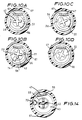
- Figures 12 to 14 show a modified form of the tool illustrated in Figures 1 to 11, wherein provision is made for the carrying of a spare cutter.
- the tool is the same as that described above and like parts are indicated with like reference characters: those parts will not be described again here.
- the tubular portion 25 of the selector 20 has a pin 70 projecting parallel to the selector axis, beyond the skirt 71 of that portion 25.
- a generally C-shaped groove 72 is formed in the block 43 and a tube 74 is positioned within that groove 72 with the tube end 75 located on the pin 70.
- the flange 57 of the sleeve 56 has an opening 76 which may come into alignment with the tube 74 upon rotation of the sleeve with respect to the selector 20 and so also the block 43.
- the configuration is such that the alignment can be achieved only when the lug 24 of the blade carrier 23 is moved further beyond the abutment surface 27 of the selector 20 - and this can be achieved only once the adjusting screw 35 has been removed so allowing the selector 20 to be pushed axially further away from the sleeve 56 than is required for the helical cut setting illustrated in Figure 3.
- This movement further beyond abutment surface 27 will be under the action of the spring 55 but is limited by the lug 24 engaging the elongate portion 47 of the clamp 45, as shown in Figure 10D.
- the tool may conveniently be used to remove a section of insulation part way along the length of a wire. This is achieved by making a first annular cut, then a helical cut from that annular cut for the required distance and finally a further annular cut at the other end of the helical cut. Thereafter, the insulation may easily be removed, for example by using a pair of side cutters.
- the sleeve 56 has a flat 67 formed along its length. This serves as a convenient reference point for operation of the tool, since in the "normal" (annular cut) setting, the flat 67 is aligned with the clamp 45. Moreover, the flat serves as a convenient surface on which to carry information such as the manufacturer's details.
Description
According to one aspect of the present invention, there is provided a wire stripper comprising a first sub-assembly comprising a sleeve, a blade carrier secured to the sleeve and a cutting blade projecting from the carrier, and a second sub-assembly comprising a selector and a wire clamp slidably mounted on the selector which clamp is arranged to hold a wire to be stripped and is spring-loaded to urge that wire against the cutting blade, the second sub-assembly being supported by and arranged for relative turning movement with respect to the first sub-assembly, and there being co-operating abutment means on the blade carrier and the selector positively to define a first cutting position where the blade is set to rotate around a held wire and a second cutting position where the blade is set to perform an axial cut along a held wire, spring means applying a rotational bias to the blade carrier to urge the carrier away from the second cutting position towards the first cutting position, the blade being moved between the first and second cutting positions by relative turning movement through substantially 90° of the second sub-assembly with respect to the first sub-assembly.
Claims (16)
- A wire stripper comprising a selector (20), a blade carrier (23) supported by the selector (20) and having a projecting cutting blade (33), the selector and blade carrier being arranged for relative turning movement, a wire clamp (45) slidably mounted on the selector (20) and arranged to hold a wire (64) to be stripped and to urge that wire against the cutting blade (33), co-operating abutment means (24,26,27,28) on the blade carrier (23) and the selector (20) positively to define first, second and third cutting positions, in the first cutting position the blade (33) being set to rotate around a held wire, in the second cutting position the carrier and blade being turned through substantially 90° from the first cutting position whereby the blade (33) is set to perform an axial cut, and in the third cutting position the carrier and blade being turned through an acute angle from the first cutting position whereby the blade (33) is set to perform a helical cut, and spring means (55) applying a rotational bias to the blade carrier (23) with respect to the selector (20) whereby the carrier (23) is torsionally urged selectively to either of the first or third cutting positions.
- A wire stripper as claimed in claim 1, wherein the abutment means (24,26,27,28) is arranged such that the blade carrier (23) is turned in one sense from the first cutting position in order to reach the second cutting position, and is turned in the opposite sense from the first cutting position in order to reach the third cutting position.
- A wire stripper as claimed in claim 1 or claim 2, wherein the co-operating abutment means includes an abutment (24) on the blade carrier (20), and first, second and third stops (26, 27 and 28) provided on the selector (20).
- A wire stripper as claimed in claim 2 and claim 3, wherein the blade carrier (23) is supported by the selector (20) for limited axial movement with respect thereto, the carrier being (23) movable from its first cutting position to its third cutting position by axial movement of the carrier (2) away from a held wire (60) to permit the carrier abutment (24) to move over the first stop (26) and turn in said opposite sense to reach the third stop (27).
- A wire stripper as claimed in claim 4, wherein the blade carrier (23) is spring urged axially with respect to the selector (20) to its position where the carrier abutment (24) may engage the first stop (26).
- A wire stripper as claimed in claim 5, wherein a helical spring (38) acts between the selector (20) and the blade carrier (23) and serves to urge the carrier rotationally away from the second cutting position.
- A wire stripper as claimed in any of the preceding claims, wherein the wire clamp (45) is mounted with respect to the selector for sliding movement substantially parallel to the blade carrier axis, and is spring-urged towards a wire-clamping position.
- A wire stripper as claimed in claim 7, wherein a single helical spring (38) serves both to urge the carrier (23) rotationally away from the second cutting position towards the first cutting position, and also to urge the wire clamp (45) towards a wire-clamping position.
- A wire stripper as claimed in any of the preceding claims, wherein an external sleeve (56) surrounds at least a part of the selector (20) and a part of the blade carrier (23), and is connected to the blade carrier to impart movement thereto with respect to the selector.
- A wire stripper as claimed in any of the preceding claims, wherein the cutting blade (33) is replaceably held in the blade carrier.
- A wire stripper as claimed in claim 9 and in claim 10, wherein there is provided means carrying a spare blade (33) arranged within the sleeve (56), parallel to the blade carrier axis and adjacent the end of the sleeve remote from the cutting blade.
- A wire stripper as claimed in claim 11, wherein the spare blade carrying means is in the form of a tube (74) within which at least one spare blade is carried, which tube (74) is held stationary with respect to the selector, and access to the spare blade may be gained by turning the sleeve to a position where an opening (76) in the sleeve (56) is aligned with the end (75) of the tube.
- A wire stripper as claimed in claim 12, wherein the opening in the sleeve (56) is aligned with the tube (74) by turning the sleeve to a position beyond any of the first, second and third cutting positions.
- A wire stripper as claimed in claim 13, wherein the sleeve (56) is moved to said aligned position by initially moving the selector (20) axially away from the blade carrier (23) to such an extent that the blade carrier is freed from said abutment means.
- A wire stripper as claimed in claim 1, wherein the wire clamp (45) slidably mounted on the selector (20) has a first portion (50,51) arranged to hold a wire (64) to be stripped and to urge that wire against the cutting blade (33) and a second portion (47) projecting inwardly of the wire stripper from the first portion, and a compression spring (55) arranged between and connected at its two ends respectively to the blade carrier (22) and the second portion (47) of the wire clamp (45), the compression spring (55) being pre-stressed to urge apart the blade carrier (23) and the second portion (47) of the wire clamp thereby to bias the wire clamp to its wire-holding position and also to apply torque to the blade carrier (23) to urge the carrier away from its said second cutting position selectively towards the first or third cutting positions.
- A wire stripper comprising a first sub-assembly comprising a sleeve (56), a blade carrier (23) secured to the sleeve and a cutting blade (33) projecting from the carrier (23), and a second sub-assembly comprising a selector (20) and a wire clamp (45) slidably mounted on the selector (20) which clamp is arranged to hold a wire (64) to be stripped and is spring-loaded to urge that wire against the cutting blade (33), the second sub-assembly being supported by and arranged for relative turning movement with respect to the first sub-assembly, and there being co-operating abutment means (24,26,28) on the blade carrier (23) and the selector (20) positively to define a first cutting position where the blade (33) is set to rotate around a held wire (64) and a second cutting position where the blade (33) is set to perform an axial cut along a held wire, spring means (55) applying a rotational bias to the blade carrier (23) to urge the carrier away from the second cutting position towards the first cutting position, the blade being moved between the first and second cutting positions by relative turning movement through substantially 90° of the second sub-assembly with respect to the first sub-assembly.
Applications Claiming Priority (3)
| Application Number | Priority Date | Filing Date | Title |
|---|---|---|---|
| GB9518674 | 1995-09-13 | ||
| GBGB9518674.8A GB9518674D0 (en) | 1995-09-13 | 1995-09-13 | Wire stripper |
| PCT/GB1996/002277 WO1997010633A1 (en) | 1995-09-13 | 1996-09-13 | Wire stripper |
Publications (2)
| Publication Number | Publication Date |
|---|---|
| EP0872003A1 EP0872003A1 (en) | 1998-10-21 |
| EP0872003B1 true EP0872003B1 (en) | 2001-12-05 |
Family
ID=10780624
Family Applications (1)
| Application Number | Title | Priority Date | Filing Date |
|---|---|---|---|
| EP96930284A Expired - Lifetime EP0872003B1 (en) | 1995-09-13 | 1996-09-13 | Wire stripper |
Country Status (5)
| Country | Link |
|---|---|
| US (1) | US6073349A (en) |
| EP (1) | EP0872003B1 (en) |
| DE (1) | DE69617740T2 (en) |
| GB (1) | GB9518674D0 (en) |
| WO (1) | WO1997010633A1 (en) |
Families Citing this family (12)
| Publication number | Priority date | Publication date | Assignee | Title |
|---|---|---|---|---|
| US6334253B1 (en) * | 2000-08-28 | 2002-01-01 | Yin-Ho Cheng | Adjustable wire stripper |
| SE0104300L (en) * | 2001-12-19 | 2003-01-21 | Pressmaster Ab | Cable Stripping Tools |
| SE0104297L (en) | 2001-12-19 | 2003-01-21 | Pressmaster Ab | Cable Stripping Tools |
| JP2006012572A (en) * | 2004-06-25 | 2006-01-12 | Agilent Technol Inc | Teflon stud for super-high resistance resistor |
| JP5014892B2 (en) * | 2007-06-25 | 2012-08-29 | 株式会社ディスコ | Blade replacement tool |
| DE102007032399B3 (en) | 2007-07-10 | 2008-09-11 | Rennsteig Werkzeuge Gmbh | Kabelabmantelwerkzeug |
| US7913394B2 (en) * | 2008-04-15 | 2011-03-29 | Hager Gregory L | Cable sheath splitter |
| US9748748B2 (en) | 2011-08-16 | 2017-08-29 | Southwire Company, Llc | Cable stripper |
| FR2992108B1 (en) * | 2012-06-14 | 2014-06-13 | Stanley Works Europe Gmbh | IMPROVED MANUAL TOOL FOR CABLE STRIPPING |
| CA3019328A1 (en) | 2016-03-27 | 2017-10-05 | Southwire Company, Llc | Cable stripper |
| CN111668619A (en) * | 2020-07-20 | 2020-09-15 | 贵州电网有限责任公司 | Jointing clamp and jointing method thereof |
| CN112152155A (en) * | 2020-08-31 | 2020-12-29 | 贵州电网有限责任公司 | Portable electric wire stripping machine |
Citations (1)
| Publication number | Priority date | Publication date | Assignee | Title |
|---|---|---|---|---|
| GB2108773A (en) * | 1980-08-29 | 1983-05-18 | Weidmueller Gmbh And Co C A | A tool for removing insulation from cables |
Family Cites Families (10)
| Publication number | Priority date | Publication date | Assignee | Title |
|---|---|---|---|---|
| US1866095A (en) * | 1930-04-29 | 1932-07-05 | Western Electric Co | Cutting tool |
| US3710654A (en) * | 1970-09-04 | 1973-01-16 | Thomas & Betts Corp | Cable stripping tool |
| GB1458366A (en) * | 1973-04-26 | 1976-12-15 | Bieganski Z | Tools for cutting |
| US3881249A (en) * | 1974-06-05 | 1975-05-06 | Ideal Ind | Cable stripper |
| DE3263749D1 (en) * | 1981-08-28 | 1985-06-27 | Weidmueller C A Gmbh Co | Wire stripping tool |
| DE4204141C1 (en) * | 1992-02-12 | 1993-06-17 | Weidmueller Interface Gmbh & Co, 4930 Detmold, De | |
| US5386632A (en) * | 1993-01-12 | 1995-02-07 | Pacific Handy Cutter, Inc. | Ergonomic utility knife/box cutter and method of making |
| JP2689882B2 (en) * | 1993-12-03 | 1997-12-10 | 日本電気株式会社 | Coaxial cable end processing tool |
| US5644843A (en) * | 1995-10-30 | 1997-07-08 | Young; Monte | Easily loaded utility knife |
| US5809652A (en) * | 1996-11-07 | 1998-09-22 | Ducret; Lucien C. | Cable stripping device |
-
1995
- 1995-09-13 GB GBGB9518674.8A patent/GB9518674D0/en active Pending
-
1996
- 1996-09-13 WO PCT/GB1996/002277 patent/WO1997010633A1/en active IP Right Grant
- 1996-09-13 EP EP96930284A patent/EP0872003B1/en not_active Expired - Lifetime
- 1996-09-13 US US09/043,199 patent/US6073349A/en not_active Expired - Lifetime
- 1996-09-13 DE DE69617740T patent/DE69617740T2/en not_active Expired - Lifetime
Patent Citations (1)
| Publication number | Priority date | Publication date | Assignee | Title |
|---|---|---|---|---|
| GB2108773A (en) * | 1980-08-29 | 1983-05-18 | Weidmueller Gmbh And Co C A | A tool for removing insulation from cables |
Also Published As
| Publication number | Publication date |
|---|---|
| WO1997010633A1 (en) | 1997-03-20 |
| DE69617740T2 (en) | 2002-07-18 |
| EP0872003A1 (en) | 1998-10-21 |
| US6073349A (en) | 2000-06-13 |
| GB9518674D0 (en) | 1995-11-15 |
| DE69617740D1 (en) | 2002-01-17 |
Similar Documents
| Publication | Publication Date | Title |
|---|---|---|
| EP0872003B1 (en) | Wire stripper | |
| KR100573204B1 (en) | Puller device | |
| US4945788A (en) | Adjustable-mid-span stripper for wire and cable | |
| US5314445A (en) | Surgical instrument | |
| US5009130A (en) | Coaxial cable stripper | |
| US5573530A (en) | Handle for a surgical instrument including a manually actuated brake | |
| US6834864B2 (en) | Chuck having quick change mechanism | |
| US20080271257A1 (en) | Wire stripping back bar knife | |
| US5653027A (en) | Cable stripper | |
| DE102007032399B3 (en) | Kabelabmantelwerkzeug | |
| US5310294A (en) | Wire-puller apparatus | |
| US4489490A (en) | Cable stripper | |
| AU2013206132B2 (en) | Electrician's tool having a foldable blade for stripping an electrical conductor | |
| US20080271255A1 (en) | Knife wire stripping tool | |
| US6138362A (en) | Cable stripper | |
| GB2153157A (en) | Co-axial cable stripping tool | |
| US6662450B1 (en) | Wire and cable stripper | |
| CN114204488A (en) | Cable outer protective layer removing tool | |
| CN116867608A (en) | Cutting tool for cable sheath | |
| EP0140397B1 (en) | Stripping device for a coaxial cable | |
| US7913394B2 (en) | Cable sheath splitter | |
| US5009005A (en) | Cable stripper | |
| US20040055160A1 (en) | Cable stripper | |
| US9136677B2 (en) | Flush cut tool | |
| EP1059025A2 (en) | Motor-driven garden tool, particularly hedge trimmer |
Legal Events
| Date | Code | Title | Description |
|---|---|---|---|
| PUAI | Public reference made under article 153(3) epc to a published international application that has entered the european phase |
Free format text: ORIGINAL CODE: 0009012 |
|
| 17P | Request for examination filed |
Effective date: 19980408 |
|
| AK | Designated contracting states |
Kind code of ref document: A1 Designated state(s): DE FR GB SE |
|
| 17Q | First examination report despatched |
Effective date: 19981023 |
|
| GRAG | Despatch of communication of intention to grant |
Free format text: ORIGINAL CODE: EPIDOS AGRA |
|
| GRAG | Despatch of communication of intention to grant |
Free format text: ORIGINAL CODE: EPIDOS AGRA |
|
| GRAH | Despatch of communication of intention to grant a patent |
Free format text: ORIGINAL CODE: EPIDOS IGRA |
|
| GRAH | Despatch of communication of intention to grant a patent |
Free format text: ORIGINAL CODE: EPIDOS IGRA |
|
| GRAA | (expected) grant |
Free format text: ORIGINAL CODE: 0009210 |
|
| AK | Designated contracting states |
Kind code of ref document: B1 Designated state(s): DE FR GB SE |
|
| REG | Reference to a national code |
Ref country code: GB Ref legal event code: IF02 |
|
| REF | Corresponds to: |
Ref document number: 69617740 Country of ref document: DE Date of ref document: 20020117 |
|
| ET | Fr: translation filed | ||
| PLBE | No opposition filed within time limit |
Free format text: ORIGINAL CODE: 0009261 |
|
| STAA | Information on the status of an ep patent application or granted ep patent |
Free format text: STATUS: NO OPPOSITION FILED WITHIN TIME LIMIT |
|
| 26N | No opposition filed | ||
| PGFP | Annual fee paid to national office [announced via postgrant information from national office to epo] |
Ref country code: SE Payment date: 20090925 Year of fee payment: 14 |
|
| REG | Reference to a national code |
Ref country code: SE Ref legal event code: EUG |
|
| PG25 | Lapsed in a contracting state [announced via postgrant information from national office to epo] |
Ref country code: SE Free format text: LAPSE BECAUSE OF NON-PAYMENT OF DUE FEES Effective date: 20100914 |
|
| PGFP | Annual fee paid to national office [announced via postgrant information from national office to epo] |
Ref country code: DE Payment date: 20140917 Year of fee payment: 19 |
|
| PGFP | Annual fee paid to national office [announced via postgrant information from national office to epo] |
Ref country code: GB Payment date: 20140912 Year of fee payment: 19 |
|
| PGFP | Annual fee paid to national office [announced via postgrant information from national office to epo] |
Ref country code: FR Payment date: 20141113 Year of fee payment: 19 |
|
| REG | Reference to a national code |
Ref country code: DE Ref legal event code: R119 Ref document number: 69617740 Country of ref document: DE |
|
| GBPC | Gb: european patent ceased through non-payment of renewal fee |
Effective date: 20150913 |
|
| REG | Reference to a national code |
Ref country code: FR Ref legal event code: ST Effective date: 20160531 |
|
| PG25 | Lapsed in a contracting state [announced via postgrant information from national office to epo] |
Ref country code: GB Free format text: LAPSE BECAUSE OF NON-PAYMENT OF DUE FEES Effective date: 20150913 Ref country code: DE Free format text: LAPSE BECAUSE OF NON-PAYMENT OF DUE FEES Effective date: 20160401 |
|
| PG25 | Lapsed in a contracting state [announced via postgrant information from national office to epo] |
Ref country code: FR Free format text: LAPSE BECAUSE OF NON-PAYMENT OF DUE FEES Effective date: 20150930 |