EP0871385B1 - Robust metal hydride hydrogen storage system - Google Patents
Robust metal hydride hydrogen storage system Download PDFInfo
- Publication number
- EP0871385B1 EP0871385B1 EP96942859A EP96942859A EP0871385B1 EP 0871385 B1 EP0871385 B1 EP 0871385B1 EP 96942859 A EP96942859 A EP 96942859A EP 96942859 A EP96942859 A EP 96942859A EP 0871385 B1 EP0871385 B1 EP 0871385B1
- Authority
- EP
- European Patent Office
- Prior art keywords
- hydrogen
- container
- storage system
- storage
- metal hydride
- Prior art date
- Legal status (The legal status is an assumption and is not a legal conclusion. Google has not performed a legal analysis and makes no representation as to the accuracy of the status listed.)
- Expired - Lifetime
Links
- UFHFLCQGNIYNRP-UHFFFAOYSA-N Hydrogen Chemical compound [H][H] UFHFLCQGNIYNRP-UHFFFAOYSA-N 0.000 title claims abstract description 84
- 239000001257 hydrogen Substances 0.000 title claims abstract description 84
- 229910052739 hydrogen Inorganic materials 0.000 title claims abstract description 84
- 229910052987 metal hydride Inorganic materials 0.000 title claims abstract description 40
- 150000004681 metal hydrides Chemical class 0.000 title claims abstract description 39
- 150000002431 hydrogen Chemical class 0.000 abstract description 3
- 239000000463 material Substances 0.000 description 11
- 238000012546 transfer Methods 0.000 description 11
- 238000004806 packaging method and process Methods 0.000 description 7
- 238000013461 design Methods 0.000 description 6
- 229910052751 metal Inorganic materials 0.000 description 5
- 239000002184 metal Substances 0.000 description 5
- 239000007789 gas Substances 0.000 description 4
- 239000007788 liquid Substances 0.000 description 4
- 238000004519 manufacturing process Methods 0.000 description 4
- 238000000034 method Methods 0.000 description 4
- 150000001875 compounds Chemical class 0.000 description 3
- 230000003247 decreasing effect Effects 0.000 description 3
- 238000012986 modification Methods 0.000 description 3
- 230000004048 modification Effects 0.000 description 3
- 239000007787 solid Substances 0.000 description 3
- 229910045601 alloy Inorganic materials 0.000 description 2
- 239000000956 alloy Substances 0.000 description 2
- 230000006835 compression Effects 0.000 description 2
- 238000007906 compression Methods 0.000 description 2
- 150000004678 hydrides Chemical class 0.000 description 2
- 229910000765 intermetallic Inorganic materials 0.000 description 2
- 150000002739 metals Chemical class 0.000 description 2
- 229910002335 LaNi5 Inorganic materials 0.000 description 1
- 229910019758 Mg2Ni Inorganic materials 0.000 description 1
- 229910000831 Steel Inorganic materials 0.000 description 1
- 229910010340 TiFe Inorganic materials 0.000 description 1
- 238000010521 absorption reaction Methods 0.000 description 1
- 238000009835 boiling Methods 0.000 description 1
- 238000006243 chemical reaction Methods 0.000 description 1
- 238000004891 communication Methods 0.000 description 1
- 238000010276 construction Methods 0.000 description 1
- 238000000354 decomposition reaction Methods 0.000 description 1
- 230000007423 decrease Effects 0.000 description 1
- 238000012938 design process Methods 0.000 description 1
- 238000003795 desorption Methods 0.000 description 1
- 230000007613 environmental effect Effects 0.000 description 1
- 239000000446 fuel Substances 0.000 description 1
- 125000004435 hydrogen atom Chemical group [H]* 0.000 description 1
- 239000012535 impurity Substances 0.000 description 1
- -1 metal hydride compound Chemical class 0.000 description 1
- 230000002441 reversible effect Effects 0.000 description 1
- 239000010959 steel Substances 0.000 description 1
- 239000000126 substance Substances 0.000 description 1
Images
Classifications
-
- F—MECHANICAL ENGINEERING; LIGHTING; HEATING; WEAPONS; BLASTING
- F17—STORING OR DISTRIBUTING GASES OR LIQUIDS
- F17C—VESSELS FOR CONTAINING OR STORING COMPRESSED, LIQUEFIED OR SOLIDIFIED GASES; FIXED-CAPACITY GAS-HOLDERS; FILLING VESSELS WITH, OR DISCHARGING FROM VESSELS, COMPRESSED, LIQUEFIED, OR SOLIDIFIED GASES
- F17C1/00—Pressure vessels, e.g. gas cylinder, gas tank, replaceable cartridge
-
- F—MECHANICAL ENGINEERING; LIGHTING; HEATING; WEAPONS; BLASTING
- F17—STORING OR DISTRIBUTING GASES OR LIQUIDS
- F17C—VESSELS FOR CONTAINING OR STORING COMPRESSED, LIQUEFIED OR SOLIDIFIED GASES; FIXED-CAPACITY GAS-HOLDERS; FILLING VESSELS WITH, OR DISCHARGING FROM VESSELS, COMPRESSED, LIQUEFIED, OR SOLIDIFIED GASES
- F17C11/00—Use of gas-solvents or gas-sorbents in vessels
-
- Y—GENERAL TAGGING OF NEW TECHNOLOGICAL DEVELOPMENTS; GENERAL TAGGING OF CROSS-SECTIONAL TECHNOLOGIES SPANNING OVER SEVERAL SECTIONS OF THE IPC; TECHNICAL SUBJECTS COVERED BY FORMER USPC CROSS-REFERENCE ART COLLECTIONS [XRACs] AND DIGESTS
- Y02—TECHNOLOGIES OR APPLICATIONS FOR MITIGATION OR ADAPTATION AGAINST CLIMATE CHANGE
- Y02E—REDUCTION OF GREENHOUSE GAS [GHG] EMISSIONS, RELATED TO ENERGY GENERATION, TRANSMISSION OR DISTRIBUTION
- Y02E60/00—Enabling technologies; Technologies with a potential or indirect contribution to GHG emissions mitigation
- Y02E60/30—Hydrogen technology
- Y02E60/32—Hydrogen storage
Definitions
- the present invention is concerned with a hydrogen storage system. More particularly, the present invention is concerned with a metal hydride hydrogen storage system.
- Hydrogen is stored conventionally as a gas or a liquid. Hydrogen storage as a gas is typically in large, bulky steel cylinders at very high pressures (e.g. 2,000 psi). Hydrogen storage as a liquid is typically in insulated containers at very low temperatures. Energy must be used to keep the temperature low to prevent the liquid hydrogen from boiling off. Hence, cryogenic hydrogen production and storage is highly inefficient. Within recent years, considerable attention has been focused on the storage of hydrogen as a metallic compound, or hydride, of various substances. Metal hydrides can store large amounts of hydrogen at low pressures in relatively small volumes. This low pressure storage of hydrogen is relatively safe and allows the construction of hydrogen containers having forms significantly different than those storing gaseous hydrogen.
- Hydridable metals are charged with hydrogen by introducing pressurized gaseous hydrogen into valved containers.
- the hydrogen gas reacts exothermically with the metal to form the metal hydride compound.
- the hydrogen is released from the metal hydride by opening the valve of the container to permit decomposition of the compound in an endothermic reaction.
- solid hydridable materials to store hydrogen is disclosed in numerous patents, such as U.S. Pat. Nos. 3,508,514, 3,516,263 and 4,036,944, These solid hydridable materials are characterized by an interrelation of temperature, pressure and hydrogen content, such that, at any given temperature, the hydrogen content of the hydridable material is determined by the partial pressure of the hydrogen in contact with that material. Generally, as temperature rises it takes a greater partial pressure of hydrogen to maintain a given concentration of hydrogen in the hydridable material. The converse is also true as temperature decreases.
- the reversible storage of hydrogen in the form of an intermetallic hydride has several advantages over conventional gaseous and liquid hydrogen storage.
- the use of metal hydrides offer pronounced volumetric advantages over compressed gas, along with much lower required pressure, a safety advantage.
- the use of metal hydrides provides excellent insurance that the hydrogen released from the containers is of very high purity.
- Metal hydride storage units have many uses and applications in a variety of industrial and laboratory environments. The diversity of applications requires a storage system that can provide the user with a reliable source of hydrogen at a variety of capacities. Small storage units are commonly used as hydrogen sources for laboratory experimentation. Much larger units are needed to provide the quantity of hydrogen necessary for vehicular transportation systems. Hence, a modular hydrogen storage system is needed that will allow for quick and easy modification of system capacity.
- the storage system regardless of the size and capacity of the container, must be robust enough to perform property and reliably under a wide range of environmental conditions.
- US-A-5 462 021 discloses a hydrogen storage system comprising a connected sequence of storage containers for metal hydride and gaseous hydrogen, wherein each container has a first-type connector at one end and a second-type connector at the other end such that the first-type connector of one end of a first container can be fit into the second-type connector at the opposite end of a second container.
- both of the connectors are in a closed position until they are brought together and when they are brought together, they are both opened so that there is a gaseous communication between the two containers.
- One object of the present invention is to provide a modular metal hydride hydrogen storage system which can provide a robust and reliable source of hydrogen that can quickly and easily be modified for a variety of applications and environments.
- a hydrogen storage system comprising at least a first storage module and optionally one or more additional storage modules connected end-to-end to form a connected sequence of storage modules, characterised in that each module comprises a container for metal hydride and gaseous hydrogen having an open end, and a closed end, opposite to said open end, said closed end having a passage port; means for introducing gaseous hydrogen into and withdrawing gaseous hydrogen from said container through said passage port; and means for connecting the closed end of the container of one storage module to the open end of the container of another storage module; and a container cap covers the open end of said first storage module.
- the present invention discloses a uniquely designed metal hydride storage module that can be connected end-to-end with similar storage modules to form a robust, reliable and well-engineered metal hydride hydrogen storage system.
- Figure 1 shows an embodiment of the metal hydride hydrogen storage system of the present invention utilizing a single metal hydride storage module 1.
- the module comprises a container 2 which may be any shape that can properly store the metal hydride material.
- Figure 1 shows an embodiment of a container 2 which is a cylinder having an open end 4 and a closed end 6 opposite the open end 4. The closed end 6 has a passage port 8.
- the hydrogen storage module 1 further comprises a heat transfer means which is necessary to transfer heat away from the metal hydride during the hydrogen absorption process (exothermic) and to transfer heat into the metal hydride during the hydrogen desorption process (endothermic).
- Figure 1 shows an embodiment of the heat transfer means comprising a plurality of heat fins 10 which are attached to container 2. The plurality of heat fins are preferably spaced equidistantly around the container 2.
- the solid metal hydride material may either partially or totally fill the interior of container 2.
- the metal hydride material used can be formed from a number of metals, alloys and intermetallic compounds which react reversibly with hydrogen at ambient temperature and modest gas pressure. Examples of compounds that may be used to form metal hydrides include, but are not limited to, the alloys from the AB 5 (e.g. LaNi 5 ), AB (e.g. TiFe) and A 2 B (e.g. Mg 2 Ni) families. Using these compound, metal hydrides can be formed readily and reversibly (i.e. hydrogenated and dehydrogenated) in the vicinity of ordinary temperatures and at modest hydrogen pressures. That portion of the interior of container 2 not filled with metal hydride material is the gaseous hydrogen region.
- AB 5 e.g. LaNi 5
- AB e.g. TiFe
- a 2 B e.g. Mg 2 Ni
- the open end 4 of the container 1 may be is sealed using the container cap 12.
- the interior surface of the container cap 12 as well as the sides of the container 2 adjacent to the open end 4 are threaded so that container cap 12 can easily screw onto the open end 4 of the container.
- a cap o-ring 14 is sandwiched between the container cap 12 and the rim of the open end 4 to ensure a tight seal so that hydrogen gas does not escape through the open end. While in this embodiment of the present invention the container cap 12 screws onto the container, other means of closing the open end of the container, such as compression fittings, plugs, etc., are also possible.
- the container cap 12 may be fitted with various types of gauges (i.e. temperature and pressure) depending on the application.
- a passage means is used to transport gaseous hydrogen into and out of the container 2.
- One embodiment of the passage means is a passage tube 16 positioned along the axis of the container.
- the passage tube 16 is impermeable to metal hydride.
- the passage tube 16 may be either permeable or impermeable to gaseous hydrogen.
- one opening of the passage tube 16 extends into the passage port 8 located in the closed end 6 of the container.
- the other opening extends into the hydrogen gas region of the interior of the container 6.
- This opening is covered with a sintered filter 18.
- the sintered filter 18 prevents impurities from passing through the passage tube 16.
- the passage tube 16 allows gaseous hydrogen to be introduced into the container and withdrawn from the container by connecting a valve 20 into the passage port 8.
- the storage capacity of the metal hydride hydrogen storage system of the present invention can be easily increased by attaching additional storage modules to the storage module 1 shown in Figure 1.
- Storage modules are connected end-to-end to form a connected sequence of storage modules.
- Figure 2 shows an embodiment of the metal hydride hydrogen storage system of the present invention using two storage modules, a first module 22 and a second module 24.
- the closed end 26 of the first storage module 22 is attached to the open end 28 of the second storage module 24. They are attached using an attachment means for keeping the two storage modules securely and firmly together.
- An embodiment of the attachment means is the adapter 30 shown in Figure 2 and Figure 3.
- the adapter 30 is preferably an annular ring with a threaded inner surface. To accommodate the adapter 30, the outer surface of each storage module's container is also threaded near both the open and closed ends. The closed end 26 of the first storage module and the open end 28 of the second storage module can thus be screwed into the opposite ends of the adapter 30 and squeezed firmly together.
- a container o-ring 32 is sandwiched between closed end 26 and the rim of open end 28 to form a tight seal between the first storage module 22 and the second storage module 24.
- this embodiment of the attachment means uses the adapter 30 shown in Figures 2 and 3, other means of connecting two storage modules are also possible. These include different types of compression fittings and clamping systems. In addition, a "quick disconnect" type of fitting may be used so that modules can easily be replaced. Moreover, the lid and container o-rings used to form the proper seals may be replaced with various types of gaskets.
- the passage port 34 of the first storage module 22 extends into the open end 28 of the second storage module. This permits the free flow of hydrogen gas between the first and second storage modules without the need to connect extraneous valves and tubes. Gaseous hydrogen may be introduced into the system or removed from the system by connecting a valve 38 to the passage port 36 of the second storage module.
- the hydrogen storage capacity of the storage system described in the present invention may be repeatedly increased by adding additional storage units in the same manner as described above.
- the storage capacity can thus be increased or decreased quickly and easily without additional devices that can add cost to the system while reducing reliability.
- the modularity of the system greatly simplifies the engineering effort necessary to design storage units of different capacities.
- An understanding of the engineering characteristics of a single storage module provides an understanding of the characteristics of larger capacity storage systems built by connecting several storage modules together.
- the design of a metal hydride hydrogen storage system requires a good understanding of the heat transfer properties of the system. As mentioned earlier, heat flows out of and into the metal hydride material as hydrogen is absorbed by the metal and released by the metal. Proper operation of the storage system requires that the underlying design includes the proper heat transfer means that can appropriately transfer heat out of and into the metal hydride.
- the design of the appropriate heat transfer mechanism depends upon many factors. These include the type and quantity of metal hydride used as well as the shape, volume and material of the container holding the metal hydride. Changing the volume of the container in order to increase hydrogen storage capacity changes the heat transfer characteristics of the storage system and requires a modification of the heat exchange system. This increases the complexity and cost of the design process.
- the capacity of the hydrogen storage system of the present invention is increased or decreased by adding or removing identical storage modules, the heat transfer characteristics of almost any capacity system can be understood in terms of the heat transfer characteristics of a single storage module. Hence, once a heat exchange system has been appropriately designed for a single module it is not necessary to re-design the system for larger systems. It is thus possible to provide a hydrogen storage system of almost any capacity which is well engineered, highly reliable and of superior quality.
- the hydrogen storage system of the present invention is built by connecting together a plurality of identical storage modules, the physical dimensions of the system may easily be adapted to the packaging space available. Such adaptability can be very important when packaging space is scarce and must be efficiently utilized. This is especially important in such industries as automotive manufacturing where, because of space limitations, component packaging is a major engineering concern, and where improper packaging can cause many assembly and quality problems.
- the metal hydride storage system of the present invention provides a way to increase hydrogen capacity quickly and easily without the need for adding valves and tubing that add cost and quality problems to the system. Valves and tubing can crack and leak from embrittlement, fatigue and external vibration, thus decreasing the reliability of the storage system. This factor is again especially important for applications in automotive manufacturing where the need to package and route extraneous fuel lines can easily be a major source of design, manufacturing and quality problems.
Landscapes
- Engineering & Computer Science (AREA)
- Mechanical Engineering (AREA)
- General Engineering & Computer Science (AREA)
- Filling Or Discharging Of Gas Storage Vessels (AREA)
- Sorption Type Refrigeration Machines (AREA)
- Hydrogen, Water And Hydrids (AREA)
Abstract
Description
- The present invention is concerned with a hydrogen storage system. More particularly, the present invention is concerned with a metal hydride hydrogen storage system.
- Hydrogen is stored conventionally as a gas or a liquid. Hydrogen storage as a gas is typically in large, bulky steel cylinders at very high pressures (e.g. 2,000 psi). Hydrogen storage as a liquid is typically in insulated containers at very low temperatures. Energy must be used to keep the temperature low to prevent the liquid hydrogen from boiling off. Hence, cryogenic hydrogen production and storage is highly inefficient.
Within recent years, considerable attention has been focused on the storage of hydrogen as a metallic compound, or hydride, of various substances. Metal hydrides can store large amounts of hydrogen at low pressures in relatively small volumes. This low pressure storage of hydrogen is relatively safe and allows the construction of hydrogen containers having forms significantly different than those storing gaseous hydrogen. Hydridable metals are charged with hydrogen by introducing pressurized gaseous hydrogen into valved containers. The hydrogen gas reacts exothermically with the metal to form the metal hydride compound. Conversely, the hydrogen is released from the metal hydride by opening the valve of the container to permit decomposition of the compound in an endothermic reaction. - The use of solid hydridable materials to store hydrogen is disclosed in numerous patents, such as U.S. Pat. Nos. 3,508,514, 3,516,263 and 4,036,944, These solid hydridable materials are characterized by an interrelation of temperature, pressure and hydrogen content, such that, at any given temperature, the hydrogen content of the hydridable material is determined by the partial pressure of the hydrogen in contact with that material. Generally, as temperature rises it takes a greater partial pressure of hydrogen to maintain a given concentration of hydrogen in the hydridable material. The converse is also true as temperature decreases.
- The reversible storage of hydrogen in the form of an intermetallic hydride has several advantages over conventional gaseous and liquid hydrogen storage. The use of metal hydrides offer pronounced volumetric advantages over compressed gas, along with much lower required pressure, a safety advantage. In addition, the use of metal hydrides provides excellent insurance that the hydrogen released from the containers is of very high purity.
- Metal hydride storage units have many uses and applications in a variety of industrial and laboratory environments. The diversity of applications requires a storage system that can provide the user with a reliable source of hydrogen at a variety of capacities. Small storage units are commonly used as hydrogen sources for laboratory experimentation. Much larger units are needed to provide the quantity of hydrogen necessary for vehicular transportation systems. Hence, a modular hydrogen storage system is needed that will allow for quick and easy modification of system capacity. The storage system, regardless of the size and capacity of the container, must be robust enough to perform property and reliably under a wide range of environmental conditions.
- The diversity of applications for metal hydride hydrogen storage also necessitates a storage system that Will allow for container. storage and packaging in many different physical locations. Such "packaging flexibility" is especially important in the transportation industry where component packaging space is often quite scarce.
- US-A-5 462 021 discloses a hydrogen storage system comprising a connected sequence of storage containers for metal hydride and gaseous hydrogen, wherein each container has a first-type connector at one end and a second-type connector at the other end such that the first-type connector of one end of a first container can be fit into the second-type connector at the opposite end of a second container. In such an hydrogen storage system, both of the connectors are in a closed position until they are brought together and when they are brought together, they are both opened so that there is a gaseous communication between the two containers.
- One object of the present invention is to provide a modular metal hydride hydrogen storage system which can provide a robust and reliable source of hydrogen that can quickly and easily be modified for a variety of applications and environments.
- This object is achieved by a hydrogen storage system comprising at least a first storage module and optionally one or more additional storage modules connected end-to-end to form a connected sequence of storage modules, characterised in that each module comprises a container for metal hydride and gaseous hydrogen having an open end, and a closed end, opposite to said open end, said closed end having a passage port; means for introducing gaseous hydrogen into and withdrawing gaseous hydrogen from said container through said passage port; and means for connecting the closed end of the container of one storage module to the open end of the container of another storage module; and a container cap covers the open end of said first storage module.
-
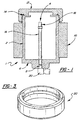
- Figure 1 depicts a single metal hydride hydrogen storage module;
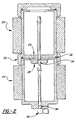
- Figure 2 depicts a connected sequence of two metal hydride hydrogen storage modules connected together by an adapter;
- Figure 3 depicts an adapter, annular in shape, used to connect one metal hydride hydrogen storage unit to another.
-
- The present invention discloses a uniquely designed metal hydride storage module that can be connected end-to-end with similar storage modules to form a robust, reliable and well-engineered metal hydride hydrogen storage system.
- Figure 1 shows an embodiment of the metal hydride hydrogen storage system of the present invention utilizing a single metal hydride storage module 1. The module comprises a
container 2 which may be any shape that can properly store the metal hydride material. Figure 1 shows an embodiment of acontainer 2 which is a cylinder having an open end 4 and a closedend 6 opposite the open end 4. The closedend 6 has apassage port 8. - The hydrogen storage module 1 further comprises a heat transfer means which is necessary to transfer heat away from the metal hydride during the hydrogen absorption process (exothermic) and to transfer heat into the metal hydride during the hydrogen desorption process (endothermic). Figure 1 shows an embodiment of the heat transfer means comprising a plurality of
heat fins 10 which are attached tocontainer 2. The plurality of heat fins are preferably spaced equidistantly around thecontainer 2. - The solid metal hydride material may either partially or totally fill the interior of
container 2. The metal hydride material used can be formed from a number of metals, alloys and intermetallic compounds which react reversibly with hydrogen at ambient temperature and modest gas pressure. Examples of compounds that may be used to form metal hydrides include, but are not limited to, the alloys from the AB5 (e.g. LaNi5), AB (e.g. TiFe) and A2B (e.g. Mg2Ni) families. Using these compound, metal hydrides can be formed readily and reversibly (i.e. hydrogenated and dehydrogenated) in the vicinity of ordinary temperatures and at modest hydrogen pressures. That portion of the interior ofcontainer 2 not filled with metal hydride material is the gaseous hydrogen region. - The open end 4 of the container 1 may be is sealed using the
container cap 12. The interior surface of thecontainer cap 12 as well as the sides of thecontainer 2 adjacent to the open end 4 are threaded so thatcontainer cap 12 can easily screw onto the open end 4 of the container. A cap o-ring 14 is sandwiched between thecontainer cap 12 and the rim of the open end 4 to ensure a tight seal so that hydrogen gas does not escape through the open end. While in this embodiment of the present invention thecontainer cap 12 screws onto the container, other means of closing the open end of the container, such as compression fittings, plugs, etc., are also possible. Furthermore, thecontainer cap 12 may be fitted with various types of gauges (i.e. temperature and pressure) depending on the application. - A passage means is used to transport gaseous hydrogen into and out of the
container 2. One embodiment of the passage means is apassage tube 16 positioned along the axis of the container. Thepassage tube 16 is impermeable to metal hydride. Thepassage tube 16 may be either permeable or impermeable to gaseous hydrogen. In the embodiment of the invention shown in Figure 1, one opening of thepassage tube 16 extends into thepassage port 8 located in the closedend 6 of the container. The other opening extends into the hydrogen gas region of the interior of thecontainer 6. This opening is covered with asintered filter 18. Thesintered filter 18 prevents impurities from passing through thepassage tube 16. Thepassage tube 16 allows gaseous hydrogen to be introduced into the container and withdrawn from the container by connecting avalve 20 into thepassage port 8. - The storage capacity of the metal hydride hydrogen storage system of the present invention can be easily increased by attaching additional storage modules to the storage module 1 shown in Figure 1. Storage modules are connected end-to-end to form a connected sequence of storage modules. Figure 2 shows an embodiment of the metal hydride hydrogen storage system of the present invention using two storage modules, a
first module 22 and asecond module 24. - The
closed end 26 of thefirst storage module 22 is attached to theopen end 28 of thesecond storage module 24. They are attached using an attachment means for keeping the two storage modules securely and firmly together. An embodiment of the attachment means is theadapter 30 shown in Figure 2 and Figure 3. Theadapter 30 is preferably an annular ring with a threaded inner surface. To accommodate theadapter 30, the outer surface of each storage module's container is also threaded near both the open and closed ends. Theclosed end 26 of the first storage module and theopen end 28 of the second storage module can thus be screwed into the opposite ends of theadapter 30 and squeezed firmly together. A container o-ring 32 is sandwiched betweenclosed end 26 and the rim ofopen end 28 to form a tight seal between thefirst storage module 22 and thesecond storage module 24. While this embodiment of the attachment means uses theadapter 30 shown in Figures 2 and 3, other means of connecting two storage modules are also possible. These include different types of compression fittings and clamping systems. In addition, a "quick disconnect" type of fitting may be used so that modules can easily be replaced. Moreover, the lid and container o-rings used to form the proper seals may be replaced with various types of gaskets. - The
passage port 34 of thefirst storage module 22 extends into theopen end 28 of the second storage module. This permits the free flow of hydrogen gas between the first and second storage modules without the need to connect extraneous valves and tubes. Gaseous hydrogen may be introduced into the system or removed from the system by connecting avalve 38 to thepassage port 36 of the second storage module. - The hydrogen storage capacity of the storage system described in the present invention may be repeatedly increased by adding additional storage units in the same manner as described above. The storage capacity can thus be increased or decreased quickly and easily without additional devices that can add cost to the system while reducing reliability.
- The modularity of the system greatly simplifies the engineering effort necessary to design storage units of different capacities. An understanding of the engineering characteristics of a single storage module provides an understanding of the characteristics of larger capacity storage systems built by connecting several storage modules together. For example, the design of a metal hydride hydrogen storage system requires a good understanding of the heat transfer properties of the system. As mentioned earlier, heat flows out of and into the metal hydride material as hydrogen is absorbed by the metal and released by the metal. Proper operation of the storage system requires that the underlying design includes the proper heat transfer means that can appropriately transfer heat out of and into the metal hydride.
- The design of the appropriate heat transfer mechanism depends upon many factors. These include the type and quantity of metal hydride used as well as the shape, volume and material of the container holding the metal hydride. Changing the volume of the container in order to increase hydrogen storage capacity changes the heat transfer characteristics of the storage system and requires a modification of the heat exchange system. This increases the complexity and cost of the design process.
- Because the capacity of the hydrogen storage system of the present invention is increased or decreased by adding or removing identical storage modules, the heat transfer characteristics of almost any capacity system can be understood in terms of the heat transfer characteristics of a single storage module. Hence, once a heat exchange system has been appropriately designed for a single module it is not necessary to re-design the system for larger systems. It is thus possible to provide a hydrogen storage system of almost any capacity which is well engineered, highly reliable and of superior quality.
- Furthermore, because the hydrogen storage system of the present invention is built by connecting together a plurality of identical storage modules, the physical dimensions of the system may easily be adapted to the packaging space available. Such adaptability can be very important when packaging space is scarce and must be efficiently utilized. This is especially important in such industries as automotive manufacturing where, because of space limitations, component packaging is a major engineering concern, and where improper packaging can cause many assembly and quality problems.
- Finally, the metal hydride storage system of the present invention provides a way to increase hydrogen capacity quickly and easily without the need for adding valves and tubing that add cost and quality problems to the system. Valves and tubing can crack and leak from embrittlement, fatigue and external vibration, thus decreasing the reliability of the storage system. This factor is again especially important for applications in automotive manufacturing where the need to package and route extraneous fuel lines can easily be a major source of design, manufacturing and quality problems.
- While the invention has been described in connection with preferred embodiments and procedures, it is to be understood that it is not intended to limit the invention to the described embodiments and procedures. On the contrary it is intended to cover all alternatives, modifications and equivalence which may be included within the scope of the invention as defined by the claims appended hereinafter.
Claims (10)
- A hydrogen storage system comprising at least a first storage module (1; 22) and optionally one or more additional storage modules (24) connected end-to-end to form a connected sequence of storage modules (22, 24), characterised in thateach module (1; 22, 24) comprises:a container (2) for metal hydride and gaseous hydrogen having an open end (4; 28), and a closed end (6; 26), opposite to said open end, said closed end (6; 26) having a passage port (8; 34; 36);means (16) for introducing gaseous hydrogen into and withdrawing gaseous hydrogen from said container (2) through said passage port (8; 34; 36); andmeans for connecting the closed end (6; 26) of the container of one storage module (22) to the open end (28) of the container of another storage module (24); anda container cap (12) covers the open end (4) of said first storage module (1; 22).
- The hydrogen storage system of claim 1, which is a connected sequence of the first storage module (22) and of the one or more additional storage modules (24) wherein the closed end (26) of the container of one module (22) of said connected sequence is connected to the open end (28) of the container of the following module (24) of said connected sequence.
- The hydrogen storage system of claim 1, wherein said means for introducing gaseous hydrogen is a passage tube (16) positioned in said container (2) and surrounded by said metal hydride, said passage tube gaseously connected to said passage port.
- The hydrogen storage system of claim 1, wherein said container (2) is a cylinder.
- The hydrogen storage system of claim 3, wherein said passage tube (16) is impermeable to gaseous hydrogen.
- The hydrogen storage system of claim 3, wherein said passage tube (16) is permeable to gaseous hydrogen.
- The hydrogen storage system of claim 1, wherein said means for connecting comprises an annular adapter (30) having a threaded interior surface, where said threaded interior surface allows the closed end (6; 26) of the container of one storage module (1; 22) and the open end (28) of the container of another storage module (24) to be threaded into opposite sides of said adapter.
- The hydrogen storage system of claim 7, wherein said means for connecting further comprises a container o-ring (32) compressed between the closed end (26) and the open end (28).
- The hydrogen storage system of claim 1, wherein each of said storage modules further comprises a heat exchange means for transferring heat into and out of said storage module.
- The hydrogen storage system of claim 9, wherein said heat exchange means is a plurality of heat fins(10) connected to the exterior of said container.
Applications Claiming Priority (3)
| Application Number | Priority Date | Filing Date | Title |
|---|---|---|---|
| US569487 | 1995-12-08 | ||
| US08/569,487 US5697221A (en) | 1995-12-08 | 1995-12-08 | Robust metal hydride hydrogen storage system |
| PCT/US1996/019230 WO1997021370A1 (en) | 1995-12-08 | 1996-12-05 | Robust metal hydride hydrogen storage system |
Publications (3)
| Publication Number | Publication Date |
|---|---|
| EP0871385A1 EP0871385A1 (en) | 1998-10-21 |
| EP0871385A4 EP0871385A4 (en) | 1999-12-01 |
| EP0871385B1 true EP0871385B1 (en) | 2004-05-12 |
Family
ID=24275650
Family Applications (1)
| Application Number | Title | Priority Date | Filing Date |
|---|---|---|---|
| EP96942859A Expired - Lifetime EP0871385B1 (en) | 1995-12-08 | 1996-12-05 | Robust metal hydride hydrogen storage system |
Country Status (8)
| Country | Link |
|---|---|
| US (1) | US5697221A (en) |
| EP (1) | EP0871385B1 (en) |
| JP (1) | JP2000502428A (en) |
| KR (1) | KR19990071893A (en) |
| AU (1) | AU1144797A (en) |
| BR (1) | BR9611925A (en) |
| DE (1) | DE69632480T2 (en) |
| WO (1) | WO1997021370A1 (en) |
Families Citing this family (17)
| Publication number | Priority date | Publication date | Assignee | Title |
|---|---|---|---|---|
| US5797269A (en) * | 1996-02-23 | 1998-08-25 | Sanyo Electric Co., Ltd. | Hydrogen storage containers |
| JPH1160201A (en) * | 1997-08-04 | 1999-03-02 | Sanritsuku:Kk | Storage container for hydrogen storage alloy |
| US5953922A (en) * | 1998-01-20 | 1999-09-21 | Stetson; Ned T. | Metal hydride hydrogen storage container with valved ports |
| US6099811A (en) * | 1998-02-13 | 2000-08-08 | Energy Conversion Devices, Inc. | Self-heating metal-hydride hydrogen storage system |
| US6672048B2 (en) * | 2001-07-10 | 2004-01-06 | Duncan Johnstone | Rotary impeller driven turbine |
| US7254983B2 (en) * | 2001-10-16 | 2007-08-14 | Hera Usa Inc. | Fuel gauge for hydrogen storage media |
| US7169489B2 (en) | 2002-03-15 | 2007-01-30 | Fuelsell Technologies, Inc. | Hydrogen storage, distribution, and recovery system |
| US7011768B2 (en) | 2002-07-10 | 2006-03-14 | Fuelsell Technologies, Inc. | Methods for hydrogen storage using doped alanate compositions |
| US6666034B1 (en) * | 2002-08-14 | 2003-12-23 | Hsu-Yang Technologies Co., Ltd. | Hydrogen storage and transportation system |
| US6755021B2 (en) | 2002-09-18 | 2004-06-29 | Stm Power, Inc. | On-board hydrogen gas production system for stirling engines |
| US20040065171A1 (en) | 2002-10-02 | 2004-04-08 | Hearley Andrew K. | Soild-state hydrogen storage systems |
| FR2924787B1 (en) * | 2007-12-10 | 2010-02-12 | Centre Nat Rech Scient | HYDROGEN STORAGE TANK. |
| TWI531405B (en) * | 2014-12-15 | 2016-05-01 | 財團法人工業技術研究院 | Leak hydrogen absorbing device, hydrogen energy utilization system and leak hydrogen absorbing method |
| WO2019026872A1 (en) * | 2017-07-31 | 2019-02-07 | 株式会社Atomis | Gas storage container |
| DE102019113063A1 (en) * | 2019-05-17 | 2020-11-19 | Unicorn Energy GmbH | Interchangeable cartridge, cartridge system and method for connecting cartridges |
| KR20220127661A (en) * | 2021-03-11 | 2022-09-20 | 현대자동차주식회사 | Assembling device for solid hydrogen storage system and method for assembling the same |
| WO2025109536A1 (en) * | 2023-11-22 | 2025-05-30 | Indian Institute Of Technology Bombay | A swappable modular metal hyride system with 1kg hydrogen storage capacity for vehicular applications |
Family Cites Families (11)
| Publication number | Priority date | Publication date | Assignee | Title |
|---|---|---|---|---|
| US1835887A (en) * | 1931-03-24 | 1931-12-08 | Franklin E Mackey | Liquid gas converter |
| US3508514A (en) | 1966-04-04 | 1970-04-28 | Vienna Arthur W | Cargo ships |
| US3516263A (en) | 1969-03-25 | 1970-06-23 | Atomic Energy Commission | Method of storing hydrogen |
| NL155630B (en) * | 1970-03-06 | 1978-01-16 | Philips Nv | DEVICE FOR CONVERTING CALORIC INTO MECHANICAL ENERGY, IN PARTICULAR A HOT GAS ENGINE. |
| US4036944A (en) | 1976-05-17 | 1977-07-19 | Shell Oil Company | Hydrogen sorbent composition and its use |
| DE3216917A1 (en) * | 1982-05-06 | 1983-11-24 | Thyssen Industrie Ag, 4300 Essen | HYDROGEN HYDRIDE STORAGE |
| US4598832A (en) * | 1984-11-13 | 1986-07-08 | Ildefonso Novoa Alonso | System of coupling cylindrical, sectioned containers |
| DE3514500C1 (en) * | 1985-04-22 | 1986-05-22 | Daimler-Benz Ag, 7000 Stuttgart | Hydrogen storage |
| US4978023A (en) * | 1990-03-22 | 1990-12-18 | Behlmann Timothy J | Insulated modular cooler |
| GB9013700D0 (en) * | 1990-06-20 | 1990-08-08 | Spirig Ernest | Container system |
| EP0560366A1 (en) * | 1992-03-12 | 1993-09-15 | Mazda Motor Corporation | Hydrogen gas supply system for hydrogen engine and method of supplying hydrogen gas to the hydrogen gas supply system |
-
1995
- 1995-12-08 US US08/569,487 patent/US5697221A/en not_active Expired - Lifetime
-
1996
- 1996-12-05 DE DE69632480T patent/DE69632480T2/en not_active Expired - Fee Related
- 1996-12-05 BR BR9611925A patent/BR9611925A/en not_active IP Right Cessation
- 1996-12-05 WO PCT/US1996/019230 patent/WO1997021370A1/en not_active Ceased
- 1996-12-05 KR KR1019980704178A patent/KR19990071893A/en not_active Ceased
- 1996-12-05 EP EP96942859A patent/EP0871385B1/en not_active Expired - Lifetime
- 1996-12-05 AU AU11447/97A patent/AU1144797A/en not_active Abandoned
- 1996-12-05 JP JP09522086A patent/JP2000502428A/en active Pending
Also Published As
| Publication number | Publication date |
|---|---|
| WO1997021370A1 (en) | 1997-06-19 |
| EP0871385A1 (en) | 1998-10-21 |
| EP0871385A4 (en) | 1999-12-01 |
| KR19990071893A (en) | 1999-09-27 |
| BR9611925A (en) | 1999-03-30 |
| US5697221A (en) | 1997-12-16 |
| DE69632480D1 (en) | 2004-06-17 |
| JP2000502428A (en) | 2000-02-29 |
| AU1144797A (en) | 1997-07-03 |
| DE69632480T2 (en) | 2005-05-12 |
Similar Documents
| Publication | Publication Date | Title |
|---|---|---|
| US5697221A (en) | Robust metal hydride hydrogen storage system | |
| US5953922A (en) | Metal hydride hydrogen storage container with valved ports | |
| US5778972A (en) | Robust metal hydride hydrogen storage system with metal hydride support structure | |
| US4133426A (en) | Hydride container | |
| US6089027A (en) | Fluid storage and dispensing system | |
| US6742554B1 (en) | Device for overheat protection for a type 4 compressed gas container | |
| US7431756B2 (en) | Modular metal hydride hydrogen storage system | |
| US4396114A (en) | Flexible means for storing and recovering hydrogen | |
| EP2805096B1 (en) | Device for storage of compressed gas, method of making the same, and method of using the same | |
| KR20070005697A (en) | Storage systems for adsorbable gaseous fuel and methods of producing the same | |
| US4135621A (en) | Hydrogen storage module | |
| US20110277846A1 (en) | Rectangular parallelepiped fluid storage and dispensing vessel | |
| EP3722653A1 (en) | Combined hydrogen storage - compression system for the filling of high pressure hydrogen tanks | |
| CA1276012C (en) | Method and apparatus for evacuating and filling heat pipes and similar closed vessels | |
| EP1715225B1 (en) | Dual-flow valve and internal processing vessel isolation system | |
| CA2239554A1 (en) | Robust metal hydride hydrogen storage system | |
| CN217208918U (en) | High-pressure hydrogen storage cylinder | |
| EP1242770B1 (en) | Modular valved hydride hydrogen storage system | |
| US10315512B2 (en) | Fuel gas storage tank and method of filling the same | |
| Bernauer | Development of hydrogen-hydride technology in the FRG | |
| CN212107832U (en) | Pressure vessel for chemical production | |
| CN112576751A (en) | Multi-layer and multi-cavity pressure container | |
| CN219530538U (en) | High-pressure hydrogen storage cylinder | |
| CN215112036U (en) | Overpressure protection structure of pressure container | |
| CN212092160U (en) | Pressure container |
Legal Events
| Date | Code | Title | Description |
|---|---|---|---|
| PUAI | Public reference made under article 153(3) epc to a published international application that has entered the european phase |
Free format text: ORIGINAL CODE: 0009012 |
|
| 17P | Request for examination filed |
Effective date: 19980625 |
|
| AK | Designated contracting states |
Kind code of ref document: A1 Designated state(s): DE FR GB |
|
| RIN1 | Information on inventor provided before grant (corrected) |
Inventor name: RANGASWAMY, KRISHNASWAMY Inventor name: STETSON, NED, T. Inventor name: VENKATESAN, SRINIVASAN Inventor name: SAPRU, KRISHNA |
|
| A4 | Supplementary search report drawn up and despatched |
Effective date: 19991015 |
|
| AK | Designated contracting states |
Kind code of ref document: A4 Designated state(s): DE FR GB |
|
| 17Q | First examination report despatched |
Effective date: 20021205 |
|
| GRAP | Despatch of communication of intention to grant a patent |
Free format text: ORIGINAL CODE: EPIDOSNIGR1 |
|
| GRAS | Grant fee paid |
Free format text: ORIGINAL CODE: EPIDOSNIGR3 |
|
| GRAA | (expected) grant |
Free format text: ORIGINAL CODE: 0009210 |
|
| AK | Designated contracting states |
Kind code of ref document: B1 Designated state(s): DE FR GB |
|
| REG | Reference to a national code |
Ref country code: GB Ref legal event code: FG4D |
|
| REF | Corresponds to: |
Ref document number: 69632480 Country of ref document: DE Date of ref document: 20040617 Kind code of ref document: P |
|
| ET | Fr: translation filed | ||
| PLBE | No opposition filed within time limit |
Free format text: ORIGINAL CODE: 0009261 |
|
| STAA | Information on the status of an ep patent application or granted ep patent |
Free format text: STATUS: NO OPPOSITION FILED WITHIN TIME LIMIT |
|
| 26N | No opposition filed |
Effective date: 20050215 |
|
| PGFP | Annual fee paid to national office [announced via postgrant information from national office to epo] |
Ref country code: GB Payment date: 20071106 Year of fee payment: 12 |
|
| PGFP | Annual fee paid to national office [announced via postgrant information from national office to epo] |
Ref country code: DE Payment date: 20071228 Year of fee payment: 12 |
|
| PGFP | Annual fee paid to national office [announced via postgrant information from national office to epo] |
Ref country code: FR Payment date: 20071204 Year of fee payment: 12 |
|
| GBPC | Gb: european patent ceased through non-payment of renewal fee |
Effective date: 20081205 |
|
| REG | Reference to a national code |
Ref country code: FR Ref legal event code: ST Effective date: 20090831 |
|
| PG25 | Lapsed in a contracting state [announced via postgrant information from national office to epo] |
Ref country code: DE Free format text: LAPSE BECAUSE OF NON-PAYMENT OF DUE FEES Effective date: 20090701 |
|
| PG25 | Lapsed in a contracting state [announced via postgrant information from national office to epo] |
Ref country code: GB Free format text: LAPSE BECAUSE OF NON-PAYMENT OF DUE FEES Effective date: 20081205 |
|
| PG25 | Lapsed in a contracting state [announced via postgrant information from national office to epo] |
Ref country code: FR Free format text: LAPSE BECAUSE OF NON-PAYMENT OF DUE FEES Effective date: 20081231 |