EP0871283B1 - A pressurization device for the rotor of a motor - Google Patents
A pressurization device for the rotor of a motor Download PDFInfo
- Publication number
- EP0871283B1 EP0871283B1 EP97117728A EP97117728A EP0871283B1 EP 0871283 B1 EP0871283 B1 EP 0871283B1 EP 97117728 A EP97117728 A EP 97117728A EP 97117728 A EP97117728 A EP 97117728A EP 0871283 B1 EP0871283 B1 EP 0871283B1
- Authority
- EP
- European Patent Office
- Prior art keywords
- rotor
- rotor shaft
- holder
- cap
- shaft
- Prior art date
- Legal status (The legal status is an assumption and is not a legal conclusion. Google has not performed a legal analysis and makes no representation as to the accuracy of the status listed.)
- Expired - Lifetime
Links
- 239000000463 material Substances 0.000 claims description 6
- 239000004033 plastic Substances 0.000 claims description 5
- 229920001169 thermoplastic Polymers 0.000 claims 1
- 239000004416 thermosoftening plastic Substances 0.000 claims 1
- 230000035882 stress Effects 0.000 description 4
- 230000032683 aging Effects 0.000 description 2
- 230000008878 coupling Effects 0.000 description 1
- 238000010168 coupling process Methods 0.000 description 1
- 238000005859 coupling reaction Methods 0.000 description 1
- 230000007423 decrease Effects 0.000 description 1
- 230000000694 effects Effects 0.000 description 1
- 239000004519 grease Substances 0.000 description 1
- 238000000034 method Methods 0.000 description 1
- 238000000465 moulding Methods 0.000 description 1
- 229920005989 resin Polymers 0.000 description 1
- 239000011347 resin Substances 0.000 description 1
- 229920005992 thermoplastic resin Polymers 0.000 description 1
Images


Classifications
-
- H—ELECTRICITY
- H02—GENERATION; CONVERSION OR DISTRIBUTION OF ELECTRIC POWER
- H02K—DYNAMO-ELECTRIC MACHINES
- H02K37/00—Motors with rotor rotating step by step and without interrupter or commutator driven by the rotor, e.g. stepping motors
- H02K37/22—Damping units
-
- H—ELECTRICITY
- H02—GENERATION; CONVERSION OR DISTRIBUTION OF ELECTRIC POWER
- H02K—DYNAMO-ELECTRIC MACHINES
- H02K5/00—Casings; Enclosures; Supports
- H02K5/04—Casings or enclosures characterised by the shape, form or construction thereof
- H02K5/16—Means for supporting bearings, e.g. insulating supports or means for fitting bearings in the bearing-shields
- H02K5/167—Means for supporting bearings, e.g. insulating supports or means for fitting bearings in the bearing-shields using sliding-contact or spherical cap bearings
- H02K5/1672—Means for supporting bearings, e.g. insulating supports or means for fitting bearings in the bearing-shields using sliding-contact or spherical cap bearings radially supporting the rotary shaft at both ends of the rotor
Definitions
- the present invention relates to a pressurization device for the rotor of a motor, which is applied to a micro motor of the type, in which a magnet is mounted on the rotor shaft and having two layers of stator coils on its outer circumference.
- Reference numeral 1 designates a stator yoke, outside which a bearing 2 is mounted and inside which a bearing 3 is mounted, which support rotatably a rotor shaft 4.
- a sleeve 5 is mounted, around the outer circumference of which a cylindrical magnet 6 is attached. Thereby, the sleeve 5 and the magnet 6 are unified.
- the length of the sleeve 5 is shorter than the spacing between the bearings 2 and 3, one end thereof is adjacent to a washer 7 through which the rotor shaft 4 is penetrated and the other end is adjacent to a plate spring 8.
- the washer 7 is in contact with the bearing 2 and the plate spring 8 is in contact with the bearing 3.
- Outside the outer circumference of the magnet 6 the inner side of the stator yoke 1 located with a little gap therebetween, and inside the yoke 1 stator coils 9 and 10 are juxtaposed.
- the spacing between the sleeve 5 of a rotor of a stepping motor and the bearing 3 that is, the dimension precision of the spacing where the plate spring 8 is accommodated depends on the precision of the length of the sleeve 5 and the precision of the spacing between the bearings 2 and 3, the tiny dimension change of the spacing influences greatly the rotor pressurization due to the plate spring 8 and a contact pressure between the sleeve 5 and the rotor shaft 4, as a result to the characteristic of the motor torque.
- a variation (mm) on a load (N) is shown in Fig. 9 and in Fig. 10 respectively. Comparing these examples, a stress variation curve at the initial use of the plate spring is shown in 1 ⁇ , which becomes 2 ⁇ after aging.
- the load is within 0.35N - 1N, and in the case of a coil spring, both in 1 ⁇ and 2 ⁇ , the load shows a little variation of 0.8N -1.2N. Accordingly, when a coil spring is employed for a motor, against the clearance of the space, in which the coil spring is accommodated, the variation of the pressurization decreases.
- a coil spring in which the variation of the pressurization due to aging is small and the influence receiving from the space variation is small, is superior and easy to be used.
- the pressurized coil spring biases the rotation force of the rotor in one rotary or one reverse direction by adding a torsion force, which causes a stepping motor to be influenced badly in its angle precision indicating the position precision at every one step and in the torque characteristic.
- a coil spring is accommodated in a holder to enable the holder easily to be assembled automatically and the structure is adapted to effect for it to keep the position provisionally after being coupled with the rotor shaft, so that the motor assembly becomes easy and the structure, which does not cause the pressurization added to the rotor to influence badly against the angle precision and the torque characteristic, is provided.
- the present invention described in the claim 1 is, to solve the above problem, characterized in that a cup-shaped base and cap are adapted to be coupled to accommodate therein a coil spring, which form a holder, and said holder is interposed between a bearing of the rotor shaft and a sleeve.
- the invention described in the claim 2 in the invention described in the claim 1, is characterized in that said base and cap are made of plastic material, at the bottom center of one of them, a non-circular opening having the diameter a little smaller than the diameter of the rotor shaft is provided and at the opposite bottom center a circular opening having a diameter a little larger than the diameter of the rotor shaft is provided.
- the invention described in the claim 3, in the inventions described in the claims 1 or 2, is characterized in that one portion of said base is provided with an elongated aperture along the rotor shaft and the cap is provided with a click to allow to slide in that aperture within a given range thereof and to engage with the end of the aperture.
- the invention described in the claim 4 in either one of the inventions described in the claims 1 to 3, is characterized in that the material of said holder is made of thermoplastic resin.
- the invention described in the claim 5, in the invention described in either one of the claims 1 to 4, is characterized in that said cap is adapted to be coupled with the holder with having a clearance.
- the base and the cap of the holder is coupled with a sufficient clearance and covers a coil spring, the base and cap of the holder are freely expanded and contracted in the state where the coil spring is accommodated therein to function resiliently. Further, since the diameter of the opening for inserting the rotor shaft and holding the holder thereon is a little smaller than the one of the rotor shaft, when the holder is put on the rotor shaft, it is in the state of half-fixed and held provisionally thereon, so that it is not easily removed therefrom.
- Fig. 1 is an embodiment of the present invention shown in a half-sectional view.
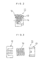
- Fig. 2 is a half-sectional view of a holder of the present invention.
- Fig. 3 is a broken side view of the holder shown in Fig. 2.
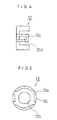
- Fig. 4 is a side view of the base of the holder.
- Fig. 5 is a front view which is taken from the right side of Fig. 4.
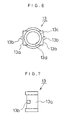
- Fig. 6 is a front view of the cap of the holder.
- Fig. 7 is a side view of Fig. 6.
- Fig. 8 is a half-sectional view of a conventional motor structure.
- Fig. 9 is a graph showing a stress variation curve of the plate spring.
- Fig. 10 is a graph showing a stress variation curve of the coil spring.
- Reference numeral 1 is a stator yoke, which supports a rotor shaft 4 rotatably by a bearing 2 fastened outside the stator yoke and a bearing 3 fastened inside the stator yoke.
- the rotor shaft 4 is fastened with a sleeve 5, and on the outer circumference of which, a cylindrical magnet 6 is mounted. So that sleeve 5 and the magnet 6 is unified.
- the length of the sleeve 5 is adapted to be approximately half of the distance between the bearings 2 and 3, and one end of the sleeve 5 is in contact with a washer 7 penetrated by the rotor shaft 4 and the other end thereof is in contact with a holder 11 of the present invention.
- the washer 7 is in contact with the bearing 2 and the holder 11 is in contact with the bearing 3, and on the outer circumference of the magnet 6, an inner circumference of the stator yoke 1 is located interposing a little gap therebetween, and inside the stator yoke 1, stator coils 9 and 10 are juxtaposed.
- the holder 11 is formed with a cup-shaped base 12 and a cap 13 accommodates a coil spring therein. The structure of the holder 11 is explained referring to Figs. 2 - 7.
- Fig. 2 shows the state of the holder 11 where the base 12 and the cap 13 are coupled and accommodate the coil spring 14 therein
- Fig. 3 is the broken state thereof
- Fig. 4 shows the side of the base 12
- Fig. 5 is a front view thereof
- Fig. 6 is a front view of the cap 13
- Fig. 7 shows the side thereof.
- Both of the base 12 and the cap 13 are formed in cup-shape using a plastic superior in molding.
- the base 12 is, as shown in Fig. 5, circular in front view and at the center of the bottom 12a an approximately octagonal hole 12b is provided, which is formed by cutting four corners of a square.
- this hole 12b the rotor shaft 4 (see Fig. 1) is inserted. Since the minimum diameter of the octagonal hole 12b (at the portions other than apexes of the octagon) is a little smaller than the diameter of the rotor shaft 4, the octagonal shape is deformed by being pushed and opened with the rotor shaft 4 into a circular shape in accordance with the diameter of the rotor shaft 4 due to the elasticity of the plastic, thereby the rotor shaft 4 can pass through the opening. Whereby, the base 12 is provisionally held by the rotor shaft 4.
- a plate shaped holder fixer 12c which is provided with an aperture 12d which is along with the axial direction.
- a pawl portion 13b (see Figs. 3, 6 and 7) provided on the side 13a of the cap 13 is adapted to be coupled.
- the pawl portion 13b engages with the end of the aperture 12d.
- the cap 13 also is made of the same material to the base 12 and adapted to be inserted therein with a little clearance and coupled with it. Due to the clearance thus provided and the nature of the plastic, at the time of coupling the cap 13 widens the fixer 12c outward, and after sliding on the inner side of the fixer 12c, the cap 13 couples in the aperture 12d. On the other hand, at the center of the bottom 13c (see Fig. 6) of the cap 13 a circular opening 13d, the diameter of which is a little larger than the diameter of the rotor shaft 4 (Fig. 1), is provided. Thereby, it becomes easy to put the holder 11 on the rotor shaft 4.
- the configuration of the opening 12b of the bottom 12a of the base 12 an octagonal one is illustrated, which is formed based on the figure to be obtained by cutting four corners of a square, however the configuration of the opening 12b is not limited to this.
- the holder is kept provisionally on the rotor shaft 4 after inserting the rotor shaft by adding a slight force.
- the material for forming the base 12 and the cap 13 are appropriate if these are flexible to some extent and small in the coefficient of friction between the holder and bearings. In the example of this invention, POM resin is used.
- the pressurization device of the present invention it becomes possible to employ a coil spring for a stepping motor, under which it is expected to obtain a good result without receiving a torsion thereof. And, in this case, when assembling the holder to the rotor shaft, due to the fastening force of the base on the rotor shaft, it is held provisionally on the rotor shaft, and that, since it is configured appropriately for an automatic assembly, the automatic assembly of the motor become possible.
Landscapes
- Engineering & Computer Science (AREA)
- Power Engineering (AREA)
- Motor Or Generator Frames (AREA)
- Connection Of Motors, Electrical Generators, Mechanical Devices, And The Like (AREA)
- Manufacture Of Motors, Generators (AREA)
Description
- The present invention relates to a pressurization device for the rotor of a motor, which is applied to a micro motor of the type, in which a magnet is mounted on the rotor shaft and having two layers of stator coils on its outer circumference.
- One example of a conventional micro motor for use of various applications is explained in accordance with Fig. 8, in which the upper half portion thereof is shown in section to show the inner structure.
Reference numeral 1 designates a stator yoke, outside which abearing 2 is mounted and inside which abearing 3 is mounted, which support rotatably arotor shaft 4. On therotor shaft 4, asleeve 5 is mounted, around the outer circumference of which acylindrical magnet 6 is attached. Thereby, thesleeve 5 and themagnet 6 are unified. - The length of the
sleeve 5 is shorter than the spacing between thebearings washer 7 through which therotor shaft 4 is penetrated and the other end is adjacent to aplate spring 8. Thewasher 7 is in contact with thebearing 2 and theplate spring 8 is in contact with thebearing 3. Outside the outer circumference of themagnet 6 the inner side of thestator yoke 1 located with a little gap therebetween, and inside theyoke 1stator coils - In such a conventional micro motor thus formed, when the
stator yoke 1 is energized by flowing the alternating current into thecoils rotor shaft 4 rotates due to the electromagnetic force functioned on themagnet 6 in accordance with a polarizing action thereof. Letting the motor be a stepping motor, if thecoils magnet 6 is functioned alternately with the electromagnetic force. When thecoils stator yoke 1 changes on therotor shaft 4 in the axial direction, since therotor shaft 4 receives a to and fro force alternately in the axial direction, which causes therotor shaft 4 to be in a unstable location and to vibrate, as a result a noise is generated. - Then, in order to avoid this, by pressing the
sleeve 5 to thebearing 2 through thewasher 7 due to the function of theplate spring 8 put on the end portion of therotor shaft 4, the location of therotor shaft 4 is fixed in the axial direction. According to the structure shown in Fig. 8, thesleeve 5 is not adapted to be in contact with thebearing 2 directly because thewasher 7 on therotor shaft 4 is interposed between thesleeve 5 and thebearing 2. A similar motor assembly is known from prior art document US 4,438,361. Accordingly, there is no trouble on the function of the motor. - However, at the time of assembling the motor, if the
plate spring 8 put on therotor shaft 4 is not fixed, it is apt to drop when assembling the rotor shaft in thestator yoke 1. To avoid this trouble, theplate spring 8 to have been adhered by grease to therotor shaft 4 while assembling, which is not suitable for an automatic assembling process and has to have relied on a hand working. Further, a mere replacement of theplate spring 8 with a coil spring has not improved the assembling work. - Since the spacing between the
sleeve 5 of a rotor of a stepping motor and thebearing 3, that is, the dimension precision of the spacing where theplate spring 8 is accommodated depends on the precision of the length of thesleeve 5 and the precision of the spacing between thebearings plate spring 8 and a contact pressure between thesleeve 5 and therotor shaft 4, as a result to the characteristic of the motor torque. - The relation of a variation (mm) on a load (N), as a representative example of stress variation characteristic of the plate spring, and as a representative example of the coil spring, is shown in Fig. 9 and in Fig. 10 respectively. Comparing these examples, a stress variation curve at the initial use of the plate spring is shown in 1 ○, which becomes 2 ○ after aging. For instance, at the variation of 0.1mm - 0.5mm, the load is within 0.35N - 1N, and in the case of a coil spring, both in 1 ○ and 2 ○, the load shows a little variation of 0.8N -1.2N. Accordingly, when a coil spring is employed for a motor, against the clearance of the space, in which the coil spring is accommodated, the variation of the pressurization decreases.
- Therefore, a coil spring, in which the variation of the pressurization due to aging is small and the influence receiving from the space variation is small, is superior and easy to be used.
- However, if such a coil spring is mounted without a coil cover or holder as well as a plate spring, the pressurized coil spring biases the rotation force of the rotor in one rotary or one reverse direction by adding a torsion force, which causes a stepping motor to be influenced badly in its angle precision indicating the position precision at every one step and in the torque characteristic.
- Then, in the present invention, a coil spring is accommodated in a holder to enable the holder easily to be assembled automatically and the structure is adapted to effect for it to keep the position provisionally after being coupled with the rotor shaft, so that the motor assembly becomes easy and the structure, which does not cause the pressurization added to the rotor to influence badly against the angle precision and the torque characteristic, is provided.
- The present invention described in the
claim 1 is, to solve the above problem, characterized in that a cup-shaped base and cap are adapted to be coupled to accommodate therein a coil spring, which form a holder, and said holder is interposed between a bearing of the rotor shaft and a sleeve. - The invention described in the
claim 2, in the invention described in theclaim 1, is characterized in that said base and cap are made of plastic material, at the bottom center of one of them, a non-circular opening having the diameter a little smaller than the diameter of the rotor shaft is provided and at the opposite bottom center a circular opening having a diameter a little larger than the diameter of the rotor shaft is provided. - The invention described in the
claim 3, in the inventions described in theclaims - The invention described in the
claim 4, in either one of the inventions described in theclaims 1 to 3, is characterized in that the material of said holder is made of thermoplastic resin. - The invention described in the
claim 5, in the invention described in either one of theclaims 1 to 4, is characterized in that said cap is adapted to be coupled with the holder with having a clearance. - Since the base and the cap of the holder is coupled with a sufficient clearance and covers a coil spring, the base and cap of the holder are freely expanded and contracted in the state where the coil spring is accommodated therein to function resiliently. Further, since the diameter of the opening for inserting the rotor shaft and holding the holder thereon is a little smaller than the one of the rotor shaft, when the holder is put on the rotor shaft, it is in the state of half-fixed and held provisionally thereon, so that it is not easily removed therefrom.
- Fig. 1 is an embodiment of the present invention shown in a half-sectional view.
- Fig. 2 is a half-sectional view of a holder of the present invention.
- Fig. 3 is a broken side view of the holder shown in Fig. 2.
- Fig. 4 is a side view of the base of the holder.
- Fig. 5 is a front view which is taken from the right side of Fig. 4.
- Fig. 6 is a front view of the cap of the holder.
- Fig. 7 is a side view of Fig. 6.
- Fig. 8 is a half-sectional view of a conventional motor structure.
- Fig. 9 is a graph showing a stress variation curve of the plate spring.
- Fig. 10 is a graph showing a stress variation curve of the coil spring.
- Hereinafter, referring to Fig. 1, an embodiment of the present invention is explained, whereby the same parts such as in Fig. 8 are illustrated in the same reference signs.
Reference numeral 1 is a stator yoke, which supports arotor shaft 4 rotatably by abearing 2 fastened outside the stator yoke and abearing 3 fastened inside the stator yoke. Therotor shaft 4 is fastened with asleeve 5, and on the outer circumference of which, acylindrical magnet 6 is mounted. So thatsleeve 5 and themagnet 6 is unified. - The length of the
sleeve 5 is adapted to be approximately half of the distance between thebearings sleeve 5 is in contact with awasher 7 penetrated by therotor shaft 4 and the other end thereof is in contact with aholder 11 of the present invention. - On the other hand, the
washer 7 is in contact with thebearing 2 and theholder 11 is in contact with thebearing 3, and on the outer circumference of themagnet 6, an inner circumference of thestator yoke 1 is located interposing a little gap therebetween, and inside thestator yoke 1,stator coils holder 11 is formed with a cup-shaped base 12 and acap 13 accommodates a coil spring therein. The structure of theholder 11 is explained referring to Figs. 2 - 7. - Fig. 2 shows the state of the
holder 11 where thebase 12 and thecap 13 are coupled and accommodate thecoil spring 14 therein, and Fig. 3 is the broken state thereof. Fig. 4 shows the side of thebase 12, Fig. 5 is a front view thereof, Fig. 6 is a front view of thecap 13 and Fig. 7 shows the side thereof. Both of thebase 12 and thecap 13 are formed in cup-shape using a plastic superior in molding. - The
base 12 is, as shown in Fig. 5, circular in front view and at the center of thebottom 12a an approximatelyoctagonal hole 12b is provided, which is formed by cutting four corners of a square. In thishole 12b the rotor shaft 4 (see Fig. 1) is inserted. Since the minimum diameter of theoctagonal hole 12b (at the portions other than apexes of the octagon) is a little smaller than the diameter of therotor shaft 4, the octagonal shape is deformed by being pushed and opened with therotor shaft 4 into a circular shape in accordance with the diameter of therotor shaft 4 due to the elasticity of the plastic, thereby therotor shaft 4 can pass through the opening. Whereby, thebase 12 is provisionally held by therotor shaft 4. - As shown in Fig. 4, there is a plate shaped
holder fixer 12c, which is provided with an aperture 12d which is along with the axial direction. Into this aperture 12d apawl portion 13b (see Figs. 3, 6 and 7) provided on theside 13a of thecap 13 is adapted to be coupled. When being coupled, since thepawl portion 13b is allowed to be displaced within the range of the aperture 12d of thefixer 12c, the total length of theholder 11 can be changed. Thepawl portion 13b engages with the end of the aperture 12d. - The
cap 13 also is made of the same material to thebase 12 and adapted to be inserted therein with a little clearance and coupled with it. Due to the clearance thus provided and the nature of the plastic, at the time of coupling thecap 13 widens thefixer 12c outward, and after sliding on the inner side of thefixer 12c, thecap 13 couples in the aperture 12d. On the other hand, at the center of the bottom 13c (see Fig. 6) of thecap 13 acircular opening 13d, the diameter of which is a little larger than the diameter of the rotor shaft 4 (Fig. 1), is provided. Thereby, it becomes easy to put theholder 11 on therotor shaft 4. When mounting theholder 11 on therotor shaft 4 of the motor, after assembling the holder by accommodating thecoil spring 14 between the base 12 and thecap 13, first therotor shaft 4 is inserted in theopening 12b of the bottom 12a of thebase 12. As mentioned above, then, since a fastening force on therotor shaft 4 is generated, at the time of putting theholder 11 on therotor shaft 4, by making use of this force, a provisional holding is carried out. Next, thesleeve 5 is mounted and by assembling therotor shaft 4 together with thewasher 7 betweenbearings coils - In the embodiment mentioned above, as the configuration of the
opening 12b of the bottom 12a of thebase 12, an octagonal one is illustrated, which is formed based on the figure to be obtained by cutting four corners of a square, however the configuration of theopening 12b is not limited to this. In essentials, it may be sufficient that the holder is kept provisionally on therotor shaft 4 after inserting the rotor shaft by adding a slight force. The material for forming thebase 12 and thecap 13 are appropriate if these are flexible to some extent and small in the coefficient of friction between the holder and bearings. In the example of this invention, POM resin is used. - According to the structure of the pressurization device of the present invention thus explained, it becomes possible to employ a coil spring for a stepping motor, under which it is expected to obtain a good result without receiving a torsion thereof. And, in this case, when assembling the holder to the rotor shaft, due to the fastening force of the base on the rotor shaft, it is held provisionally on the rotor shaft, and that, since it is configured appropriately for an automatic assembly, the automatic assembly of the motor become possible.
Claims (5)
- A rotor pressurization device for a motor which comprises a stator having a pair of bearings, and a rotor having a cylindrical magnet opposing an inner circumference of the stator with a gap therefrom, a shaft rotatably supported by the pair of bearings, and a sleeve disposed around the shaft and inside the magnet, said rotor pressurization device having a spring located around the shaft, characterized in that said holder comprising a base and a cap is provided around the shaft, located between the sleeve and one bearing of the pair and accommodates the spring.
- A rotor pressurization device for a motor according to claim 1, wherein said base and said cap are made of a plastic material, one of which has at the center of its bottom a non-circular opening having a smaller diameter than that of the rotor shaft which is deformed by being pushed and opened with the rotor shaft, and the other of which has at the center of its bottom a circular opening having a diameter a larger than the diameter of the rotor shaft.
- A rotor pressurizing device for a motor according to the claim 1 or 2, wherein said base comprises apertures along the axial direction of the rotor and said cap is provided with a pawl portion to be coupled in the aperture and allowed toslide within a given range, to engage with the end of the aperture.
- A rotor pressurizing device for a motor according to one of the claims 1-3, wherein material of said holder is a thermoplastic.
- A rotor pressurizing device for a motor according to one of the claims 1-4, wherein said cap is coupled with the base with a clearance.
Applications Claiming Priority (3)
| Application Number | Priority Date | Filing Date | Title |
|---|---|---|---|
| JP11034297A JP3393400B2 (en) | 1997-04-11 | 1997-04-11 | Motor rotor preloading device |
| JP11034297 | 1997-04-11 | ||
| JP110342/97 | 1997-04-11 |
Publications (3)
| Publication Number | Publication Date |
|---|---|
| EP0871283A2 EP0871283A2 (en) | 1998-10-14 |
| EP0871283A3 EP0871283A3 (en) | 2000-04-26 |
| EP0871283B1 true EP0871283B1 (en) | 2002-12-18 |
Family
ID=14533333
Family Applications (1)
| Application Number | Title | Priority Date | Filing Date |
|---|---|---|---|
| EP97117728A Expired - Lifetime EP0871283B1 (en) | 1997-04-11 | 1997-10-14 | A pressurization device for the rotor of a motor |
Country Status (4)
| Country | Link |
|---|---|
| US (1) | US5856718A (en) |
| EP (1) | EP0871283B1 (en) |
| JP (1) | JP3393400B2 (en) |
| DE (1) | DE69717964T2 (en) |
Families Citing this family (9)
| Publication number | Priority date | Publication date | Assignee | Title |
|---|---|---|---|---|
| JP3318531B2 (en) * | 1998-08-04 | 2002-08-26 | ミネベア株式会社 | Rotating electric machine and its bearing structure |
| JP2000228856A (en) * | 1999-02-05 | 2000-08-15 | Mitsubishi Electric Corp | Stepping motor |
| US6844636B2 (en) * | 1999-12-17 | 2005-01-18 | Encap Motor Corporation | Spindle motor with encapsulated stator and method of making same |
| JP4823425B2 (en) * | 2001-01-15 | 2011-11-24 | ミネベア株式会社 | DC motor |
| JP4354714B2 (en) | 2003-02-26 | 2009-10-28 | ミネベア株式会社 | motor |
| JP2006014578A (en) * | 2004-05-24 | 2006-01-12 | Minebea Co Ltd | Stepping motor |
| US9722478B2 (en) * | 2013-04-05 | 2017-08-01 | Nidec Sankyo Corporation | Stepping motor |
| JP6157940B2 (en) * | 2013-06-12 | 2017-07-05 | 日本電産サンキョー株式会社 | motor |
| CN114054607A (en) * | 2021-11-19 | 2022-02-18 | 遵义市大地和电气有限公司 | Rotor riveting device of rotary transformer sensor |
Family Cites Families (4)
| Publication number | Priority date | Publication date | Assignee | Title |
|---|---|---|---|---|
| USRE25992E (en) * | 1966-03-22 | Rotary solenoid having a stepped output | ||
| US4438361A (en) * | 1982-02-24 | 1984-03-20 | Imc Magnetics Corp. | Stepper motor having rotor with limited axial movement |
| DE3417127A1 (en) * | 1984-05-09 | 1985-11-14 | Papst-Motoren GmbH & Co KG, 7742 St Georgen | SMALL FAN |
| DE4341889A1 (en) * | 1993-12-08 | 1995-06-14 | Siemens Ag | Short-circuit rotor motor with an electromagnetically ventilated spring pressure brake mounted on the front |
-
1997
- 1997-04-11 JP JP11034297A patent/JP3393400B2/en not_active Expired - Fee Related
- 1997-10-08 US US08/947,387 patent/US5856718A/en not_active Expired - Lifetime
- 1997-10-14 EP EP97117728A patent/EP0871283B1/en not_active Expired - Lifetime
- 1997-10-14 DE DE69717964T patent/DE69717964T2/en not_active Expired - Lifetime
Also Published As
| Publication number | Publication date |
|---|---|
| EP0871283A2 (en) | 1998-10-14 |
| JPH10290548A (en) | 1998-10-27 |
| US5856718A (en) | 1999-01-05 |
| DE69717964D1 (en) | 2003-01-30 |
| EP0871283A3 (en) | 2000-04-26 |
| JP3393400B2 (en) | 2003-04-07 |
| DE69717964T2 (en) | 2009-09-24 |
Similar Documents
| Publication | Publication Date | Title |
|---|---|---|
| JP4809430B2 (en) | Electric motor and transmission drive unit for adjusting drive in automobile | |
| EP1617094B1 (en) | Small-sized motor and method of manufacturing the same | |
| US20100043207A1 (en) | Stepping motor being conveniently assembled | |
| KR100361410B1 (en) | Dc motor | |
| EP0871283B1 (en) | A pressurization device for the rotor of a motor | |
| KR950015917A (en) | Outer rotor brushless DC motor | |
| AU758137B2 (en) | Electric motor | |
| US20080007136A1 (en) | Rotating electric machine having improved arrangement of brush holder for effectively dissipating heat generated by brush | |
| US6479918B1 (en) | Drilling implement | |
| EP1176702A1 (en) | Coreless motor | |
| KR100454459B1 (en) | A motor | |
| US6657347B2 (en) | Rotor | |
| US20070194648A1 (en) | Rotor for an electrical machine with improved temperature stability | |
| US4893038A (en) | Device for limiting direction of rotation of synchronous motor | |
| US6933637B2 (en) | Electric motor | |
| US4480206A (en) | Motor having stationary shaft and method of assembling it | |
| GB2302215A (en) | Hand machine tool electric motor | |
| EP0296715A1 (en) | A housing for an electric motor and a method of making same | |
| JP3652509B2 (en) | Sensor magnet device for motor | |
| JP2002291192A (en) | Electric power steering device | |
| US20030094871A1 (en) | Spring elemnt for compensating axial play in a motor shaft of an electric motor | |
| JP3124691B2 (en) | Magnet fixing structure of rotating machine | |
| JP3827135B2 (en) | Manufacturing method of small motor | |
| JP3503794B2 (en) | motor | |
| JPH09247906A (en) | Brush holder |
Legal Events
| Date | Code | Title | Description |
|---|---|---|---|
| PUAI | Public reference made under article 153(3) epc to a published international application that has entered the european phase |
Free format text: ORIGINAL CODE: 0009012 |
|
| AK | Designated contracting states |
Kind code of ref document: A2 Designated state(s): DE FR GB IT |
|
| AX | Request for extension of the european patent |
Free format text: AL;LT;LV;RO;SI |
|
| PUAL | Search report despatched |
Free format text: ORIGINAL CODE: 0009013 |
|
| AK | Designated contracting states |
Kind code of ref document: A3 Designated state(s): AT BE CH DE DK ES FI FR GB GR IE IT LI LU MC NL PT SE |
|
| AX | Request for extension of the european patent |
Free format text: AL;LT;LV;RO;SI |
|
| 17P | Request for examination filed |
Effective date: 20001019 |
|
| AKX | Designation fees paid |
Free format text: DE FR GB IT |
|
| 17Q | First examination report despatched |
Effective date: 20010829 |
|
| GRAG | Despatch of communication of intention to grant |
Free format text: ORIGINAL CODE: EPIDOS AGRA |
|
| GRAG | Despatch of communication of intention to grant |
Free format text: ORIGINAL CODE: EPIDOS AGRA |
|
| GRAH | Despatch of communication of intention to grant a patent |
Free format text: ORIGINAL CODE: EPIDOS IGRA |
|
| GRAH | Despatch of communication of intention to grant a patent |
Free format text: ORIGINAL CODE: EPIDOS IGRA |
|
| GRAA | (expected) grant |
Free format text: ORIGINAL CODE: 0009210 |
|
| AK | Designated contracting states |
Kind code of ref document: B1 Designated state(s): DE FR GB IT |
|
| REG | Reference to a national code |
Ref country code: GB Ref legal event code: FG4D |
|
| REF | Corresponds to: |
Ref document number: 69717964 Country of ref document: DE Date of ref document: 20030130 Kind code of ref document: P Ref document number: 69717964 Country of ref document: DE Date of ref document: 20030130 |
|
| ET | Fr: translation filed | ||
| PLBE | No opposition filed within time limit |
Free format text: ORIGINAL CODE: 0009261 |
|
| STAA | Information on the status of an ep patent application or granted ep patent |
Free format text: STATUS: NO OPPOSITION FILED WITHIN TIME LIMIT |
|
| 26N | No opposition filed |
Effective date: 20030919 |
|
| PGFP | Annual fee paid to national office [announced via postgrant information from national office to epo] |
Ref country code: IT Payment date: 20081029 Year of fee payment: 12 |
|
| PGFP | Annual fee paid to national office [announced via postgrant information from national office to epo] |
Ref country code: FR Payment date: 20081014 Year of fee payment: 12 |
|
| PGFP | Annual fee paid to national office [announced via postgrant information from national office to epo] |
Ref country code: GB Payment date: 20081008 Year of fee payment: 12 |
|
| REG | Reference to a national code |
Ref country code: FR Ref legal event code: ST Effective date: 20100630 |
|
| PG25 | Lapsed in a contracting state [announced via postgrant information from national office to epo] |
Ref country code: FR Free format text: LAPSE BECAUSE OF NON-PAYMENT OF DUE FEES Effective date: 20091102 |
|
| PG25 | Lapsed in a contracting state [announced via postgrant information from national office to epo] |
Ref country code: GB Free format text: LAPSE BECAUSE OF NON-PAYMENT OF DUE FEES Effective date: 20091014 |
|
| PGFP | Annual fee paid to national office [announced via postgrant information from national office to epo] |
Ref country code: DE Payment date: 20101006 Year of fee payment: 14 |
|
| PG25 | Lapsed in a contracting state [announced via postgrant information from national office to epo] |
Ref country code: IT Free format text: LAPSE BECAUSE OF NON-PAYMENT OF DUE FEES Effective date: 20091014 |
|
| PG25 | Lapsed in a contracting state [announced via postgrant information from national office to epo] |
Ref country code: DE Free format text: LAPSE BECAUSE OF NON-PAYMENT OF DUE FEES Effective date: 20120501 |
|
| REG | Reference to a national code |
Ref country code: DE Ref legal event code: R119 Ref document number: 69717964 Country of ref document: DE Effective date: 20120501 |