EP0871274A1 - Angepasstes Ladegerät für NiMeH-Batterien - Google Patents
Angepasstes Ladegerät für NiMeH-Batterien Download PDFInfo
- Publication number
- EP0871274A1 EP0871274A1 EP98102036A EP98102036A EP0871274A1 EP 0871274 A1 EP0871274 A1 EP 0871274A1 EP 98102036 A EP98102036 A EP 98102036A EP 98102036 A EP98102036 A EP 98102036A EP 0871274 A1 EP0871274 A1 EP 0871274A1
- Authority
- EP
- European Patent Office
- Prior art keywords
- charging
- batteries
- diode
- nimeh
- voltage
- Prior art date
- Legal status (The legal status is an assumption and is not a legal conclusion. Google has not performed a legal analysis and makes no representation as to the accuracy of the status listed.)
- Granted
Links
Images
Classifications
-
- H—ELECTRICITY
- H02—GENERATION; CONVERSION OR DISTRIBUTION OF ELECTRIC POWER
- H02J—ELECTRIC POWER NETWORKS; CIRCUIT ARRANGEMENTS OR SYSTEMS FOR SUPPLYING OR DISTRIBUTING ELECTRIC POWER; SYSTEMS FOR STORING ELECTRIC ENERGY
- H02J7/00—Circuit arrangements for charging or discharging batteries or for supplying loads from batteries
- H02J7/60—Circuit arrangements for charging or discharging batteries or for supplying loads from batteries including safety or protection arrangements
- H02J7/68—Circuit arrangements for charging or discharging batteries or for supplying loads from batteries including safety or protection arrangements using circuits for correcting or protecting against reverse-polarity
-
- H—ELECTRICITY
- H01—ELECTRIC ELEMENTS
- H01M—PROCESSES OR MEANS, e.g. BATTERIES, FOR THE DIRECT CONVERSION OF CHEMICAL ENERGY INTO ELECTRICAL ENERGY
- H01M10/00—Secondary cells; Manufacture thereof
- H01M10/42—Methods or arrangements for servicing or maintenance of secondary cells or secondary half-cells
- H01M10/44—Methods for charging or discharging
-
- H—ELECTRICITY
- H02—GENERATION; CONVERSION OR DISTRIBUTION OF ELECTRIC POWER
- H02J—ELECTRIC POWER NETWORKS; CIRCUIT ARRANGEMENTS OR SYSTEMS FOR SUPPLYING OR DISTRIBUTING ELECTRIC POWER; SYSTEMS FOR STORING ELECTRIC ENERGY
- H02J7/00—Circuit arrangements for charging or discharging batteries or for supplying loads from batteries
- H02J7/40—Circuit arrangements for charging or discharging batteries or for supplying loads from batteries characterised by the exchange of charge or discharge related data
- H02J7/443—Circuit arrangements for charging or discharging batteries or for supplying loads from batteries characterised by the exchange of charge or discharge related data using passive battery identification means, e.g. resistors or capacitors
-
- H—ELECTRICITY
- H02—GENERATION; CONVERSION OR DISTRIBUTION OF ELECTRIC POWER
- H02J—ELECTRIC POWER NETWORKS; CIRCUIT ARRANGEMENTS OR SYSTEMS FOR SUPPLYING OR DISTRIBUTING ELECTRIC POWER; SYSTEMS FOR STORING ELECTRIC ENERGY
- H02J7/00—Circuit arrangements for charging or discharging batteries or for supplying loads from batteries
- H02J7/485—Circuit arrangements for charging or discharging batteries or for supplying loads from batteries with provisions for charging different types of batteries
-
- H—ELECTRICITY
- H01—ELECTRIC ELEMENTS
- H01M—PROCESSES OR MEANS, e.g. BATTERIES, FOR THE DIRECT CONVERSION OF CHEMICAL ENERGY INTO ELECTRICAL ENERGY
- H01M50/00—Constructional details or processes of manufacture of the non-active parts of electrochemical cells other than fuel cells, e.g. hybrid cells
- H01M50/50—Current conducting connections for cells or batteries
- H01M50/572—Means for preventing undesired use or discharge
- H01M50/574—Devices or arrangements for the interruption of current
-
- Y—GENERAL TAGGING OF NEW TECHNOLOGICAL DEVELOPMENTS; GENERAL TAGGING OF CROSS-SECTIONAL TECHNOLOGIES SPANNING OVER SEVERAL SECTIONS OF THE IPC; TECHNICAL SUBJECTS COVERED BY FORMER USPC CROSS-REFERENCE ART COLLECTIONS [XRACs] AND DIGESTS
- Y02—TECHNOLOGIES OR APPLICATIONS FOR MITIGATION OR ADAPTATION AGAINST CLIMATE CHANGE
- Y02E—REDUCTION OF GREENHOUSE GAS [GHG] EMISSIONS, RELATED TO ENERGY GENERATION, TRANSMISSION OR DISTRIBUTION
- Y02E60/00—Enabling technologies; Technologies with a potential or indirect contribution to GHG emissions mitigation
- Y02E60/10—Energy storage using batteries
Definitions
- the invention relates to an accumulator housing for portable electronic devices, especially for portable telephones, which with electrical connections for connection with the device to be supplied and a separate charging contact.
- Portable electronic devices especially portable phones, are in shape with power sources provided by accumulators. These batteries are arranged in battery cases that are separable from the housing and can be charged separately. Such battery case are inserted into guide rails on the back of the phone, while simultaneously the electrical contact is made and there is a lock to prevent accidental Avoid loosening the battery pack from the phone or the device to be supplied.
- accumulator housings In addition to the electrical connections for connection to the device to be supplied such accumulator housings often have special charging contacts for connecting the accumulators serve in the charger and via which polarity charging of the connected Accumulators should be prevented. For this purpose, a diode is connected to the charging circuit.
- the invention has for its object to provide an accumulator housing, which Contains NiMeH batteries and in which a full charge of the batteries is guaranteed when connected to the usually available chargers.
- the NiMeH battery is additionally switched into the charging circuit Diode increases the charging voltage of the batteries to the NiCd level and it turns on Safe shutdown when the specified, possibly temperature-compensated, is reached Switch-off voltage guaranteed.
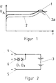
- the charge voltage profile of a conventional NiCd battery is designated 1.
- the voltage curve 2 represents the voltage curve in a NiMeH accumulator.
- the switch-off voltage of the charger is designated U A.
- the NiMeH battery 3 has discharge contacts 4 and 5 and an additional charging contact 6.
- a diode D1 is connected in a known manner, which prevents polarity charging of the battery 3 to be charged. If the NiCd batteries normally used are replaced by NiMeH batteries in such an arrangement with a diode D1, the cut-off voltage U A is not reliably reached due to the shifted charging curve 2 of NiMeH batteries shown in FIG.
- the additional diode D2 is therefore provided, which with regard to its Forward voltage is dimensioned so that it is the product of the number of connected Accumulators and the difference in the charging voltages of a NiCd accumulator and corresponds to a NiMeH battery.
- a Schottky diode is expediently used as the diode D2 selected with a forward voltage of about 0.25 V.
- the dashed line in FIG. 1 then results Charging voltage curve 2a shown.
- NiMeH batteries can be charged in terms of their charging voltage largely made compatible with NiCd batteries.
- the second diode D2 according to the invention in series with that in a known manner
- Existing diode D1 becomes the apparent, externally visible charging voltage of the accumulator battery increased and thus adapted to the charging technology for NiCd batteries.
- There charging and discharging contacts are separated in the arrangements according to the invention the diodes have no influence on the operating behavior of the connected device.
Landscapes
- Engineering & Computer Science (AREA)
- Power Engineering (AREA)
- Manufacturing & Machinery (AREA)
- Chemical & Material Sciences (AREA)
- Chemical Kinetics & Catalysis (AREA)
- Electrochemistry (AREA)
- General Chemical & Material Sciences (AREA)
- Charge And Discharge Circuits For Batteries Or The Like (AREA)
- Secondary Cells (AREA)
Abstract
Description
Claims (2)
- Akkumulatorengehäuse für tragbare elektrische Geräte, insbesondere für tragbare Telefone, mit elektrischen Anschlüssen zur Verbindung an das zu versorgende Gerät und einem getrennten Ladekontakt, wobei im Ladestromkreis eine Diode angeordnet ist, die die Akkumulatoren gegen polverkehrte Ladung schützt, dadurch gekennzeichnet, daß in Reihe mit dieser Diode (D1) eine zusätzliche zweite Diode (D2) geschaltet ist, wobei die Durchlaßspannung der Diode (D2) so gewählt ist, daß sie etwa dem Produkt aus der Zahl der im Akkumulatorengehäuse angeordneten NiMeH-Akkumulatoren (3) und der Differenz der Ladespannung zwischen NiMeH- und NiCd-Akkumulatoren entspricht.
- Akkumulatorengehäuse nach Anspruch 1, dadurch gekennzeichnet, daß es 6 NiMeH-Akkumulatoren (3) enthält und daß die Diode (D2) eine Durchlaßspannung von etwa 0,25 V besitzt.
Applications Claiming Priority (2)
| Application Number | Priority Date | Filing Date | Title |
|---|---|---|---|
| DE29706354U | 1997-04-10 | ||
| DE29706354U DE29706354U1 (de) | 1997-04-10 | 1997-04-10 | Angepaßtes Ladegerät für NiMeH-Batterien |
Publications (2)
| Publication Number | Publication Date |
|---|---|
| EP0871274A1 true EP0871274A1 (de) | 1998-10-14 |
| EP0871274B1 EP0871274B1 (de) | 2002-11-20 |
Family
ID=8038699
Family Applications (1)
| Application Number | Title | Priority Date | Filing Date |
|---|---|---|---|
| EP98102036A Expired - Lifetime EP0871274B1 (de) | 1997-04-10 | 1998-02-06 | Angepasstes Ladegerät für NiMeH-Batterien |
Country Status (3)
| Country | Link |
|---|---|
| EP (1) | EP0871274B1 (de) |
| AT (1) | ATE228276T1 (de) |
| DE (2) | DE29706354U1 (de) |
Families Citing this family (1)
| Publication number | Priority date | Publication date | Assignee | Title |
|---|---|---|---|---|
| AU710580B3 (en) * | 1998-11-26 | 1999-09-23 | Shih, Hung Ming | Improved device of a micro mobile phone battery charger |
Citations (4)
| Publication number | Priority date | Publication date | Assignee | Title |
|---|---|---|---|---|
| DE2710662A1 (de) * | 1977-03-11 | 1979-02-01 | Maack Elmewe | Schaltungsanordnung zur gewinnung der ladespannung eines akkumulators durch spannungsabfall an einem in reihe mit einem stromkreis geschalteten nichtlinearen widerstand, vorzugsweise einem halbleiter |
| US4422031A (en) * | 1980-12-17 | 1983-12-20 | Sab Nife Ab | Method and device for charging an electrical accumulator battery by means of solar-cells |
| US4775826A (en) * | 1987-04-27 | 1988-10-04 | Aviation Ignition Accessories | Battery system for auxiliary aircraft power |
| DE19532013A1 (de) * | 1995-08-31 | 1997-03-06 | Bosch Gmbh Robert | Akkumulator und Verfahren zur Erkennung des Akkumulatortyps |
-
1997
- 1997-04-10 DE DE29706354U patent/DE29706354U1/de not_active Expired - Lifetime
-
1998
- 1998-02-06 EP EP98102036A patent/EP0871274B1/de not_active Expired - Lifetime
- 1998-02-06 AT AT98102036T patent/ATE228276T1/de not_active IP Right Cessation
- 1998-02-06 DE DE59806313T patent/DE59806313D1/de not_active Expired - Fee Related
Patent Citations (4)
| Publication number | Priority date | Publication date | Assignee | Title |
|---|---|---|---|---|
| DE2710662A1 (de) * | 1977-03-11 | 1979-02-01 | Maack Elmewe | Schaltungsanordnung zur gewinnung der ladespannung eines akkumulators durch spannungsabfall an einem in reihe mit einem stromkreis geschalteten nichtlinearen widerstand, vorzugsweise einem halbleiter |
| US4422031A (en) * | 1980-12-17 | 1983-12-20 | Sab Nife Ab | Method and device for charging an electrical accumulator battery by means of solar-cells |
| US4775826A (en) * | 1987-04-27 | 1988-10-04 | Aviation Ignition Accessories | Battery system for auxiliary aircraft power |
| DE19532013A1 (de) * | 1995-08-31 | 1997-03-06 | Bosch Gmbh Robert | Akkumulator und Verfahren zur Erkennung des Akkumulatortyps |
Also Published As
| Publication number | Publication date |
|---|---|
| DE59806313D1 (de) | 2003-01-02 |
| EP0871274B1 (de) | 2002-11-20 |
| DE29706354U1 (de) | 1997-06-05 |
| ATE228276T1 (de) | 2002-12-15 |
Similar Documents
| Publication | Publication Date | Title |
|---|---|---|
| DE4100571C2 (de) | Batterie mit einer Hauptbatterie und einer Ersatzbatterie | |
| DE3706238C2 (de) | Vorrichtung zur elektrischen Energiespeicherung | |
| DE4337786A1 (de) | Batterie mit einem an der Batterie angeschlossenen Spannungsumsetzer | |
| DD148845A5 (de) | Batterieeinheit mit dc zu dc konverter | |
| DE10338082A1 (de) | Anzeigeschaltung für die Batterieladung | |
| DE2851398A1 (de) | Batterieladegeraet | |
| WO2021099204A1 (de) | Überbrückung eines batteriemanagementsystems in einem unterseeboot im gefahrenfall | |
| DE102015120285B4 (de) | Batterie, Fahrzeug mit einer solchen Batterie und Verwendung einer solchen Batterie | |
| WO2007059784A1 (de) | Akkumulator zum verbinden mit einem verbraucher | |
| EP0871274B1 (de) | Angepasstes Ladegerät für NiMeH-Batterien | |
| AT404526B (de) | Einrichtung zum selektiven entladen einzelner zellen eines wiederaufladbaren akkumulators | |
| EP1911138A1 (de) | Vorrichtung und verfahren zum aufladen einer ersten batterie aus einer zweiten batterie | |
| EP3316432A1 (de) | Stromversorgungsanordnung mit einer schnittstelle zum betreiben eines mehrspannungssystems | |
| EP0609564A2 (de) | Verfahren und Vorrichtung zum Aufladen einer Batterieeinheit | |
| DE60222767T2 (de) | Stromversorgungseinrichtung | |
| EP0843396B1 (de) | Vorrichtung zur Stromversorgung eines elektronischen Gerätes | |
| EP3219536B1 (de) | Modulares system für schnellladefähige traktionsbatterie für flurförderzeug | |
| DE102017010673A1 (de) | Elektrische Schaltungsanordnung und Verfahren zum Vorladen einer Zwischenkreiskapazität eines Zwischenkreises der elektrischen Schaltungsanordnung | |
| DE102018116480A1 (de) | Batterieschaltung mit Multiplexer-Batteriemodulen | |
| EP0677912B1 (de) | Ladeschaltung für Batterien | |
| DE10293585B4 (de) | Energiespeichervorrichtung | |
| EP1282213A2 (de) | Elektrische Verbrauchseinheit | |
| EP0875978B1 (de) | Akkumulator-betriebenes Gerät | |
| DE20313781U1 (de) | Elektrisch betreibbares, tragbares Gerät, insbesondere Taschenleuchte und Schaltung für ein derartiges Gerät | |
| DE112007003447T5 (de) | Kombinierte Gleichstromquelle |
Legal Events
| Date | Code | Title | Description |
|---|---|---|---|
| PUAI | Public reference made under article 153(3) epc to a published international application that has entered the european phase |
Free format text: ORIGINAL CODE: 0009012 |
|
| AK | Designated contracting states |
Kind code of ref document: A1 Designated state(s): AT BE CH DE DK ES FI FR GB IE IT LI NL PT SE |
|
| AX | Request for extension of the european patent |
Free format text: AL;LT;LV;MK;RO;SI |
|
| 17P | Request for examination filed |
Effective date: 19980821 |
|
| AKX | Designation fees paid |
Free format text: AT BE CH DE DK ES FI FR GB IE IT LI NL PT SE |
|
| RAP1 | Party data changed (applicant data changed or rights of an application transferred) |
Owner name: VARTA GERAETEBATTERIE GMBH |
|
| 17Q | First examination report despatched |
Effective date: 20000921 |
|
| GRAG | Despatch of communication of intention to grant |
Free format text: ORIGINAL CODE: EPIDOS AGRA |
|
| RAP1 | Party data changed (applicant data changed or rights of an application transferred) |
Owner name: MICROBATTERIE GMBH |
|
| GRAG | Despatch of communication of intention to grant |
Free format text: ORIGINAL CODE: EPIDOS AGRA |
|
| GRAH | Despatch of communication of intention to grant a patent |
Free format text: ORIGINAL CODE: EPIDOS IGRA |
|
| GRAH | Despatch of communication of intention to grant a patent |
Free format text: ORIGINAL CODE: EPIDOS IGRA |
|
| GRAH | Despatch of communication of intention to grant a patent |
Free format text: ORIGINAL CODE: EPIDOS IGRA |
|
| GRAA | (expected) grant |
Free format text: ORIGINAL CODE: 0009210 |
|
| AK | Designated contracting states |
Kind code of ref document: B1 Designated state(s): AT BE CH DE DK ES FI FR GB IE IT LI NL PT SE |
|
| PG25 | Lapsed in a contracting state [announced via postgrant information from national office to epo] |
Ref country code: IE Free format text: LAPSE BECAUSE OF FAILURE TO SUBMIT A TRANSLATION OF THE DESCRIPTION OR TO PAY THE FEE WITHIN THE PRESCRIBED TIME-LIMIT Effective date: 20021120 Ref country code: FI Free format text: LAPSE BECAUSE OF FAILURE TO SUBMIT A TRANSLATION OF THE DESCRIPTION OR TO PAY THE FEE WITHIN THE PRESCRIBED TIME-LIMIT Effective date: 20021120 |
|
| REF | Corresponds to: |
Ref document number: 228276 Country of ref document: AT Date of ref document: 20021215 Kind code of ref document: T |
|
| REG | Reference to a national code |
Ref country code: GB Ref legal event code: FG4D Free format text: NOT ENGLISH |
|
| REG | Reference to a national code |
Ref country code: CH Ref legal event code: EP |
|
| GBT | Gb: translation of ep patent filed (gb section 77(6)(a)/1977) |
Effective date: 20021202 |
|
| REG | Reference to a national code |
Ref country code: IE Ref legal event code: FG4D Free format text: GERMAN |
|
| REF | Corresponds to: |
Ref document number: 59806313 Country of ref document: DE Date of ref document: 20030102 |
|
| RAP2 | Party data changed (patent owner data changed or rights of a patent transferred) |
Owner name: VARTA MICROBATTERY GMBH |
|
| PGFP | Annual fee paid to national office [announced via postgrant information from national office to epo] |
Ref country code: GB Payment date: 20030203 Year of fee payment: 6 |
|
| PG25 | Lapsed in a contracting state [announced via postgrant information from national office to epo] |
Ref country code: AT Free format text: LAPSE BECAUSE OF NON-PAYMENT OF DUE FEES Effective date: 20030206 |
|
| PGFP | Annual fee paid to national office [announced via postgrant information from national office to epo] |
Ref country code: FR Payment date: 20030218 Year of fee payment: 6 |
|
| PG25 | Lapsed in a contracting state [announced via postgrant information from national office to epo] |
Ref country code: SE Free format text: LAPSE BECAUSE OF FAILURE TO SUBMIT A TRANSLATION OF THE DESCRIPTION OR TO PAY THE FEE WITHIN THE PRESCRIBED TIME-LIMIT Effective date: 20030220 Ref country code: PT Free format text: LAPSE BECAUSE OF FAILURE TO SUBMIT A TRANSLATION OF THE DESCRIPTION OR TO PAY THE FEE WITHIN THE PRESCRIBED TIME-LIMIT Effective date: 20030220 Ref country code: DK Free format text: LAPSE BECAUSE OF FAILURE TO SUBMIT A TRANSLATION OF THE DESCRIPTION OR TO PAY THE FEE WITHIN THE PRESCRIBED TIME-LIMIT Effective date: 20030220 |
|
| PG25 | Lapsed in a contracting state [announced via postgrant information from national office to epo] |
Ref country code: LI Free format text: LAPSE BECAUSE OF NON-PAYMENT OF DUE FEES Effective date: 20030228 Ref country code: CH Free format text: LAPSE BECAUSE OF NON-PAYMENT OF DUE FEES Effective date: 20030228 Ref country code: BE Free format text: LAPSE BECAUSE OF NON-PAYMENT OF DUE FEES Effective date: 20030228 |
|
| NLT2 | Nl: modifications (of names), taken from the european patent patent bulletin |
Owner name: VARTA MICROBATTERY GMBH |
|
| PG25 | Lapsed in a contracting state [announced via postgrant information from national office to epo] |
Ref country code: ES Free format text: LAPSE BECAUSE OF FAILURE TO SUBMIT A TRANSLATION OF THE DESCRIPTION OR TO PAY THE FEE WITHIN THE PRESCRIBED TIME-LIMIT Effective date: 20030529 |
|
| ET | Fr: translation filed | ||
| REG | Reference to a national code |
Ref country code: IE Ref legal event code: FD4D Ref document number: 0871274E Country of ref document: IE |
|
| PG25 | Lapsed in a contracting state [announced via postgrant information from national office to epo] |
Ref country code: NL Free format text: LAPSE BECAUSE OF NON-PAYMENT OF DUE FEES Effective date: 20030901 |
|
| PLBE | No opposition filed within time limit |
Free format text: ORIGINAL CODE: 0009261 |
|
| STAA | Information on the status of an ep patent application or granted ep patent |
Free format text: STATUS: NO OPPOSITION FILED WITHIN TIME LIMIT |
|
| REG | Reference to a national code |
Ref country code: CH Ref legal event code: PL |
|
| NLV4 | Nl: lapsed or anulled due to non-payment of the annual fee |
Effective date: 20030901 |
|
| 26N | No opposition filed |
Effective date: 20030821 |
|
| PG25 | Lapsed in a contracting state [announced via postgrant information from national office to epo] |
Ref country code: GB Free format text: LAPSE BECAUSE OF NON-PAYMENT OF DUE FEES Effective date: 20040206 |
|
| PGFP | Annual fee paid to national office [announced via postgrant information from national office to epo] |
Ref country code: DE Payment date: 20040315 Year of fee payment: 7 |
|
| GBPC | Gb: european patent ceased through non-payment of renewal fee |
Effective date: 20040206 |
|
| PG25 | Lapsed in a contracting state [announced via postgrant information from national office to epo] |
Ref country code: FR Free format text: LAPSE BECAUSE OF NON-PAYMENT OF DUE FEES Effective date: 20041029 |
|
| REG | Reference to a national code |
Ref country code: FR Ref legal event code: ST |
|
| PG25 | Lapsed in a contracting state [announced via postgrant information from national office to epo] |
Ref country code: IT Free format text: LAPSE BECAUSE OF NON-PAYMENT OF DUE FEES;WARNING: LAPSES OF ITALIAN PATENTS WITH EFFECTIVE DATE BEFORE 2007 MAY HAVE OCCURRED AT ANY TIME BEFORE 2007. THE CORRECT EFFECTIVE DATE MAY BE DIFFERENT FROM THE ONE RECORDED. Effective date: 20050206 |
|
| PG25 | Lapsed in a contracting state [announced via postgrant information from national office to epo] |
Ref country code: DE Free format text: LAPSE BECAUSE OF NON-PAYMENT OF DUE FEES Effective date: 20050901 |