EP0870989B1 - Fuel-injection arrangement for a gas turbine combustor - Google Patents
Fuel-injection arrangement for a gas turbine combustor Download PDFInfo
- Publication number
- EP0870989B1 EP0870989B1 EP98302714A EP98302714A EP0870989B1 EP 0870989 B1 EP0870989 B1 EP 0870989B1 EP 98302714 A EP98302714 A EP 98302714A EP 98302714 A EP98302714 A EP 98302714A EP 0870989 B1 EP0870989 B1 EP 0870989B1
- Authority
- EP
- European Patent Office
- Prior art keywords
- fuel
- outlets
- gas turbine
- turbine combustor
- series
- Prior art date
- Legal status (The legal status is an assumption and is not a legal conclusion. Google has not performed a legal analysis and makes no representation as to the accuracy of the status listed.)
- Expired - Lifetime
Links
- 238000002347 injection Methods 0.000 title claims description 22
- 239000007924 injection Substances 0.000 title claims description 22
- 239000000446 fuel Substances 0.000 claims description 57
- 238000011144 upstream manufacturing Methods 0.000 claims description 14
- 238000002485 combustion reaction Methods 0.000 claims description 12
- 208000015181 infectious disease Diseases 0.000 claims 1
- 239000000203 mixture Substances 0.000 description 7
- 238000000034 method Methods 0.000 description 5
- 230000004907 flux Effects 0.000 description 4
- 239000007789 gas Substances 0.000 description 3
- 230000008033 biological extinction Effects 0.000 description 2
- 230000035515 penetration Effects 0.000 description 2
- 238000004513 sizing Methods 0.000 description 2
- 230000004323 axial length Effects 0.000 description 1
- 230000004888 barrier function Effects 0.000 description 1
- 239000000567 combustion gas Substances 0.000 description 1
- 230000007423 decrease Effects 0.000 description 1
- 238000010586 diagram Methods 0.000 description 1
- 230000000694 effects Effects 0.000 description 1
- 239000000839 emulsion Substances 0.000 description 1
- 238000009987 spinning Methods 0.000 description 1
- 239000013589 supplement Substances 0.000 description 1
- 230000009469 supplementation Effects 0.000 description 1
- 230000001502 supplementing effect Effects 0.000 description 1
- 238000004804 winding Methods 0.000 description 1
Images


Classifications
-
- F—MECHANICAL ENGINEERING; LIGHTING; HEATING; WEAPONS; BLASTING
- F23—COMBUSTION APPARATUS; COMBUSTION PROCESSES
- F23R—GENERATING COMBUSTION PRODUCTS OF HIGH PRESSURE OR HIGH VELOCITY, e.g. GAS-TURBINE COMBUSTION CHAMBERS
- F23R3/00—Continuous combustion chambers using liquid or gaseous fuel
- F23R3/28—Continuous combustion chambers using liquid or gaseous fuel characterised by the fuel supply
- F23R3/286—Continuous combustion chambers using liquid or gaseous fuel characterised by the fuel supply having fuel-air premixing devices
-
- F—MECHANICAL ENGINEERING; LIGHTING; HEATING; WEAPONS; BLASTING
- F23—COMBUSTION APPARATUS; COMBUSTION PROCESSES
- F23C—METHODS OR APPARATUS FOR COMBUSTION USING FLUID FUEL OR SOLID FUEL SUSPENDED IN A CARRIER GAS OR AIR
- F23C7/00—Combustion apparatus characterised by arrangements for air supply
- F23C7/002—Combustion apparatus characterised by arrangements for air supply the air being submitted to a rotary or spinning motion
- F23C7/004—Combustion apparatus characterised by arrangements for air supply the air being submitted to a rotary or spinning motion using vanes
-
- F—MECHANICAL ENGINEERING; LIGHTING; HEATING; WEAPONS; BLASTING
- F23—COMBUSTION APPARATUS; COMBUSTION PROCESSES
- F23R—GENERATING COMBUSTION PRODUCTS OF HIGH PRESSURE OR HIGH VELOCITY, e.g. GAS-TURBINE COMBUSTION CHAMBERS
- F23R3/00—Continuous combustion chambers using liquid or gaseous fuel
- F23R3/02—Continuous combustion chambers using liquid or gaseous fuel characterised by the air-flow or gas-flow configuration
- F23R3/04—Air inlet arrangements
- F23R3/10—Air inlet arrangements for primary air
- F23R3/12—Air inlet arrangements for primary air inducing a vortex
- F23R3/14—Air inlet arrangements for primary air inducing a vortex by using swirl vanes
-
- F—MECHANICAL ENGINEERING; LIGHTING; HEATING; WEAPONS; BLASTING
- F23—COMBUSTION APPARATUS; COMBUSTION PROCESSES
- F23C—METHODS OR APPARATUS FOR COMBUSTION USING FLUID FUEL OR SOLID FUEL SUSPENDED IN A CARRIER GAS OR AIR
- F23C2900/00—Special features of, or arrangements for combustion apparatus using fluid fuels or solid fuels suspended in air; Combustion processes therefor
- F23C2900/07001—Air swirling vanes incorporating fuel injectors
Definitions
- the invention concerns a fuel-injection arrangement for a combustor of a gas-turbine engine, and in particular a fuel-injection arrangement enabling reliable performance at low load conditions of said engine.
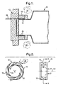
- Figure 1 shows part of a gas-turbine engine comprising a combustion chamber 10, a fuel-inlet head 12 and a radial swirler 14 disposed therebetween.
- the swirler 14 which is commonly used in gas turbine engines as a mixing device to mix fuel and air for supply to the combustion chamber, is configured as illustrated in Figure 2 and comprises a series of vanes 16 equally spaced around a circumference of the swirler, the vanes forming a corresponding series of passageways 18 for the flow of mixing air 20 through the swirler from a radially outer to a radially inner region thereof.
- the vanes are shaped and disposed such as to impart to the incoming air a tangential component, whereby the air is caused to "swirl" around the longitudinal axis 22 of the swirler, the air also being caused to exit the swirler at a downstream region thereof and enter the combustion chamber 10 (see arrows 21).
- trailing-edge region 24 of the vanes 16 - i.e. trailing-edge in terms of air flow through the vane arrangement - are conventionally disposed a series of fuel outlets 26 fed from a fuel inlet conduit 28 connected to the fuel head 12.
- the outlets or holes 26 are of uniform diameter and are evenly spaced axially along the trailing edge. Use of such holes evenly spaced along at least most of the length of the trailing edge promotes better mixing of fuel and air by making for a uniform distibution of the fuel along the axial length of the swirler.
- EP-A-0 747 636 relates to a low-emulsion combustion system in which a lean premix combustion mode is enabled by an upstream "dome" part of the combustor in which the vanes of a fixed axial swirler have internal radial fuel passageways leading to radially spaced fuel injection outlets for distributing the fuel more uniformly across the air flow into the combustor.
- the variation in radial component of momentum preferably takes the form of a variation in a radial component of velocity, which may achieved by arranging for the outlets in the series to be of varying size.
- outlets may be smallest in an axially upstream portion of said pre-chamber region and the variation in outlet size in said series may be monotonic referred to said longitudinal axis.
- Said variation may be a continuous variation or alternatively a stepped variation. It may be linear over at least a part of said series of outlets.
- the outlets which may be substantially equally spaced, may be configured such that a direction of fuel jets exiting said outlets is substantially radial.
- the outlets may be disposed in a swirler portion of said pre-chamber region, and/or they may be disposed in an intermediate portion of said pre-chamber region between a swirler portion thereof and said main-chamber region.
- said series of outlets may be incorporated into each of at least some of said vanes at a trailing edge thereof.
- the outlets may be disposed in a wall of said intermediate portion.
- the outlets may be provided in fuel posts situated in said pre-chamber region.
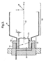
- FIG 3 which shows the same engine arrangement as in Figure 1 and includes a prior-art swirler
- a body of fuel and air 23 rotating around the swirler axis 22 moving in a direction away from the swirler and toward the combustion chamber 10.
- This rotating body can be likened to a spinning tube with an effective tube wall consisting of an air/fuel mixture and having a thickness "T" and turning in corkscrew fashion.
- three airflow velocity components can be identified: an axial component (U) pointing in a direction parallel to the swirler axis 22, a radial component (V) normal to the swirler axis 22, and a tangential component (W) about the swirler axis 22.
- the combustion flame has an upstream flame face in the region of the swirler back-face 30 and a downstream flame face in or towards the combustion chamber facing the swirler.
- the downstream flame face withdraws progressively to the upstream face so that at minimum operating load (or on engine starting) there exists only a small pilot flame which is located in the swirler region.
- the upstream flame-face zone is a fuel-weak region and without some means of fuel supplementation to this region the pilot flame would tend to extinguish at low-load settings.
- One known way of supplementing the provision of fuel to the pilot flame under these circumstances is to inject fuel directly into the region from a fuel injector means situated at the back-face of the swirler. Such a method is generally effective in sustaining a flame at low-load settings, but has the drawback of adding to the overall constructional complexity of the combustor assembly.
- the present invention provides a swirler which enhances the radial momentum of the fuel jets leaving the fuel outlets in the afore-mentioned fuel-weak region at the upstream end of the swirler. This has the effect of enabling the fuel jets at that part of the swirler to penetrate through the "tube” wall, thereby to supplement the fuel supply to the pilot flame within the "tube", thus maintaining the stability of the flame at low load settings without the need for supplementary fuel provision.
- the preferred way of increasing radial momentum according to the invention is to increase the radial velocity of the fuel jets.
- This enhancement of radial-velocity component reinforces an existing velocity characteristic of the swirler which can be seen by reference to Figure 4.
- Figure 4(a) a typical profile graph of velocity components as a function of radial distance from the swirler axis for the fuel-air mixture exiting the swirler at an axial position adjacent the swirler back-face 30 is shown. It can be seen that the radial component is the largest component at this point and the axial component the weakest.
- the radial velocity component is the weakest and the tangential component is the strongest.
- the tangential component is already well established and the radial component is not significantly greater than in the downstream-end case shown in Figure 4(c).
- the fuel-jet holes are reduced to a size giving a value of V F sufficient to yield a momentum flux ratio of greater than unity, which will then ensure penetration of the fuel through the wall.
- the hole size required varies according to wall density and will therefore be different for each engine combustor configuration.
- the constant k is arrived at empirically by making incremental adjustments to an actual system, and for a typical system might lie in the region of 1.25.
- each vane is fed with fuel along a conduit 42 lying roughly parallel to a median, approximately tangential, axis 44 of the vane, the conduit 42 then changing direction by approximately 90° to lie roughly in a radial direction 46 oriented towards the axis 22 of the swirler.
- the line of exit of the fuel may, however, in practice lie anywhere between the median line 44 and the radial line 46.
- the fuel outlets may be allocated to each vane of the swirler, or alternatively may be restricted to some vanes only, e.g. every other vane.
- variable hole-sizing technique in the combustor pre-chamber wall region shown as 50 in Figure 3, where there may still be an effective rotating body of fuel-air mixture having a wall thickness T nearby.
- the whole pre-chamber region 51 thus comprises both the swirler region 14 and the afore-mentioned region 50 intermediate the swirler and the main-chamber portion 52 of the combustion chamber 10.
- the present inventive fuel-injection technique may be incorporated into either the swirler, or the intermediate chamber area 50, or both.
- Figure 8 shows stepped holes 60, 62, 64, 66, 68 in both areas.
- the use of fuel posts to supply the fuel applies equally to the swirler portion 14 and to the intermediate portion 50 and, where the present inventive fuel-injection technique is employed in both portions, an extended length of post can be used in simple manner.
- the variable-sized fuel outlets are incorporated into the wall of the intermediate portion 50 rather than in adjacent fuel posts, fuel may be supplied to those outlets either from an extension of the fuel-gallery system supplying the swirler outlets, or from some additional system, whichever is convenient.
- mixing of fuel and air upstream of the intermediate portion may be by means of a swirler or by any other appropriate method.
Landscapes
- Engineering & Computer Science (AREA)
- Chemical & Material Sciences (AREA)
- Combustion & Propulsion (AREA)
- Mechanical Engineering (AREA)
- General Engineering & Computer Science (AREA)
Description
- The invention concerns a fuel-injection arrangement for a combustor of a gas-turbine engine, and in particular a fuel-injection arrangement enabling reliable performance at low load conditions of said engine.
- Provision is made in gas turbine engines to inject fuel into a region upstream of the main combustor region of the engine for mixing with air and eventual burning in the main combustor region.
- Figure 1 shows part of a gas-turbine engine comprising a
combustion chamber 10, a fuel-inlet head 12 and aradial swirler 14 disposed therebetween. Theswirler 14, which is commonly used in gas turbine engines as a mixing device to mix fuel and air for supply to the combustion chamber, is configured as illustrated in Figure 2 and comprises a series ofvanes 16 equally spaced around a circumference of the swirler, the vanes forming a corresponding series ofpassageways 18 for the flow of mixingair 20 through the swirler from a radially outer to a radially inner region thereof. - The vanes are shaped and disposed such as to impart to the incoming air a tangential component, whereby the air is caused to "swirl" around the
longitudinal axis 22 of the swirler, the air also being caused to exit the swirler at a downstream region thereof and enter the combustion chamber 10 (see arrows 21). - Along the trailing-
edge region 24 of the vanes 16 - i.e. trailing-edge in terms of air flow through the vane arrangement - are conventionally disposed a series offuel outlets 26 fed from afuel inlet conduit 28 connected to thefuel head 12. The outlets orholes 26 are of uniform diameter and are evenly spaced axially along the trailing edge. Use of such holes evenly spaced along at least most of the length of the trailing edge promotes better mixing of fuel and air by making for a uniform distibution of the fuel along the axial length of the swirler. EP-A-0 747 636 relates to a low-emulsion combustion system in which a lean premix combustion mode is enabled by an upstream "dome" part of the combustor in which the vanes of a fixed axial swirler have internal radial fuel passageways leading to radially spaced fuel injection outlets for distributing the fuel more uniformly across the air flow into the combustor. - In accordance with the present invention, there is provided insert the winding of claim 1 without reference numbers. The variation in radial component of momentum preferably takes the form of a variation in a radial component of velocity, which may achieved by arranging for the outlets in the series to be of varying size.
- The outlets may be smallest in an axially upstream portion of said pre-chamber region and the variation in outlet size in said series may be monotonic referred to said longitudinal axis.
- Said variation may be a continuous variation or alternatively a stepped variation. It may be linear over at least a part of said series of outlets.
- The outlets, which may be substantially equally spaced, may be configured such that a direction of fuel jets exiting said outlets is substantially radial.
- The outlets may be disposed in a swirler portion of said pre-chamber region, and/or they may be disposed in an intermediate portion of said pre-chamber region between a swirler portion thereof and said main-chamber region. In the former case, where said swirler portion comprises a plurality of vanes, said series of outlets may be incorporated into each of at least some of said vanes at a trailing edge thereof. In the latter case, the outlets may be disposed in a wall of said intermediate portion. Alternatively, the outlets may be provided in fuel posts situated in said pre-chamber region.
- An embodiment of the invention will now be described, by way of example only, with reference to the drawings, of which:
- Figure 1 is a sectional view of part of a gas-turbine engine incorporating a conventional swirler;
- Figure 2 shows the swirler of Figure 1 in both side- and end-elevations;
- Figure 3 is a view of a gas-turbine engine corresponding to that of Figure 1 and showing a dynamic aspect of the fuel-air mixture inside the swirler;
- Figures 4(a), 4(b) and 4(c) are side views of the swirler showing a velocity profile for the fuel-air mixture at upstream-end, two-thirds from upstream-end and downstream-end axial points, respectively, of the swirler;
- Figures 5(a) and 5(b) show two alternative fuel-outlet size distribution profiles for the swirler of the present invention;
- Figure 6 shows an embodiment of the swirler according to the invention in which fuel is supplied to the swirler by way of fuel posts,
- Figure 7 is an end-view of the swirler according to the invention including radially oriented fuel outlets, and
- Figure 8 is a partial view of Figure 3 showing the use of the variable-sized outlets according to the invention in an intermediate portion of a pre-chamber region of the combustion chamber.
-
- The operation of the swirler according to the invention is now explained with reference to Figure 3. In Figure 3, which shows the same engine arrangement as in Figure 1 and includes a prior-art swirler, it can be seen that, in operation, in a radially central region of the
swirler 14 there is a body of fuel andair 23 rotating around theswirler axis 22 moving in a direction away from the swirler and toward thecombustion chamber 10. This rotating body can be likened to a spinning tube with an effective tube wall consisting of an air/fuel mixture and having a thickness "T" and turning in corkscrew fashion. In this central region of the swirler three airflow velocity components can be identified: an axial component (U) pointing in a direction parallel to theswirler axis 22, a radial component (V) normal to theswirler axis 22, and a tangential component (W) about theswirler axis 22. - In a gas turbine combustor of the type shown in Figures 1 and 3, the combustion flame has an upstream flame face in the region of the swirler back-
face 30 and a downstream flame face in or towards the combustion chamber facing the swirler. As engine load decreases and with less fuel supplied, the downstream flame face withdraws progressively to the upstream face so that at minimum operating load (or on engine starting) there exists only a small pilot flame which is located in the swirler region. Typically, the upstream flame-face zone is a fuel-weak region and without some means of fuel supplementation to this region the pilot flame would tend to extinguish at low-load settings. This is because in a fuel-weak mixture the flame spreads to find fuel and in so doing is weakened, to the point at which extinction of the flame occurs - so-called "weak extinction". One reason for the region being fuel-weak is that the afore-mentioned tube wall acts as a barrier to the incoming fuel-air mixture from the swirler. Furthermore, inside the so-called tube is a counter-flowing mass of partly burnt (and therefore fuel-weak) combustion gases drawn from the combustion chamber. - One known way of supplementing the provision of fuel to the pilot flame under these circumstances is to inject fuel directly into the region from a fuel injector means situated at the back-face of the swirler. Such a method is generally effective in sustaining a flame at low-load settings, but has the drawback of adding to the overall constructional complexity of the combustor assembly.
- The present invention provides a swirler which enhances the radial momentum of the fuel jets leaving the fuel outlets in the afore-mentioned fuel-weak region at the upstream end of the swirler. This has the effect of enabling the fuel jets at that part of the swirler to penetrate through the "tube" wall, thereby to supplement the fuel supply to the pilot flame within the "tube", thus maintaining the stability of the flame at low load settings without the need for supplementary fuel provision.
- The preferred way of increasing radial momentum according to the invention is to increase the radial velocity of the fuel jets. This enhancement of radial-velocity component reinforces an existing velocity characteristic of the swirler which can be seen by reference to Figure 4. In Figure 4(a) a typical profile graph of velocity components as a function of radial distance from the swirler axis for the fuel-air mixture exiting the swirler at an axial position adjacent the swirler back-
face 30 is shown. It can be seen that the radial component is the largest component at this point and the axial component the weakest. By contrast, at the downstream face of the swirler (see Figure 4(c)) the radial velocity component is the weakest and the tangential component is the strongest. At an intermediate position, e.g. two-thirds of the way from the upstream end-face 30 (Figure 4(b)), the tangential component is already well established and the radial component is not significantly greater than in the downstream-end case shown in Figure 4(c). - For the jets of fuel nearest the pilot flame to actually reach the flame, they must penetrate through the "tube" wall and must therefore have sufficient radial momentum. It is of benefit that the radial velocity of the airflow is already greatest in this area, but it is not strong enough by itself to carry fuel through to the flame. Even when the additional radial momentum given by the fuel jets is taken into account, there is not sufficient energy to breach the wall if the conventional swirler design is used.
- The invention takes the step of sizing the holes nearest the
upstream end 30 smaller than those in the mid- and end-region, which increases the velocity of the fuel-jet passing through those holes. This increase in velocity produces a corresponding increase in the momentum flux ratio, which is defined as:
ρ F is fuel density
VF is fuel velocity
ρ A is air-wall density
VA is air-wall velocity.
The fuel-jet holes are reduced to a size giving a value of VF sufficient to yield a momentum flux ratio of greater than unity, which will then ensure penetration of the fuel through the wall. The hole size required varies according to wall density and will therefore be different for each engine combustor configuration. The hole size may be obtained by application of the following formula:
dF is the diameter of the fuel jet,
ymax is maximum fuel-jet penetration required, and
k is a constant.
The constant k is arrived at empirically by making incremental adjustments to an actual system, and for a typical system might lie in the region of 1.25. - The size of the holes varies progressively over the length of the trailing edge of the vane, the distribution being either continuous, i.e. each hole along the edge being larger than the previous one, or stepped, i.e. hole size varies in discrete jumps. These two cases are illustrated in Figures 5(a) and 5(b), respectively. In the case of Figure 5(b) three
small holes 32 are shown on the lefthand side of the diagram, likewise threeholes 34 of an intermediate size, and finally twolarge holes 36. By contrast, in Figure 5(a) allholes 38 are of different diameters. It goes without saying that these representations are exemplary only, and the numbers of holes and their distribution will vary considerably in practice and depending on the application. - Whereas it has been assumed in the description of the invention so far that fuel will be introduced into the vanes themselves, so that the fuel outlets are holes formed in the vanes, it is also possible to employ fuel posts to carry the fuel into the swirler. Such a scheme is shown very schematically in Figure 6, where two
posts 40 connected to theinlet conduit 28 extend into the swirler in the area just inside the trailingedge 24 of the vanes. Holes are formed in these posts as they were in the vane-fed scheme shown, for example, in Figure 5, and the dimensions of the holes are, as already explained, different over the length of the post. - It is preferable to arrange the fuel outlets so that the fuel passing through them is aimed as near as possible towards the
central axis 22 of the swirler in order to maximise the radial component of velocity of the fuel. An example of such an arrangement is shown in Figure 7, in which each vane is fed with fuel along aconduit 42 lying roughly parallel to a median, approximately tangential,axis 44 of the vane, theconduit 42 then changing direction by approximately 90° to lie roughly in aradial direction 46 oriented towards theaxis 22 of the swirler. The line of exit of the fuel may, however, in practice lie anywhere between themedian line 44 and theradial line 46. - The fuel outlets may be allocated to each vane of the swirler, or alternatively may be restricted to some vanes only, e.g. every other vane.
- Although the invention has been described in connection with its implementation in a swirler, it is also possible to incorporate the variable hole-sizing technique in the combustor pre-chamber wall region shown as 50 in Figure 3, where there may still be an effective rotating body of fuel-air mixture having a wall thickness T nearby. The whole
pre-chamber region 51 thus comprises both theswirler region 14 and the afore-mentionedregion 50 intermediate the swirler and the main-chamber portion 52 of thecombustion chamber 10. - The present inventive fuel-injection technique may be incorporated into either the swirler, or the
intermediate chamber area 50, or both. Figure 8 shows steppedholes swirler portion 14 and to theintermediate portion 50 and, where the present inventive fuel-injection technique is employed in both portions, an extended length of post can be used in simple manner. Where, alternatively, the variable-sized fuel outlets are incorporated into the wall of theintermediate portion 50 rather than in adjacent fuel posts, fuel may be supplied to those outlets either from an extension of the fuel-gallery system supplying the swirler outlets, or from some additional system, whichever is convenient. - Where the invention is applied to the
intermediate portion 50 only, mixing of fuel and air upstream of the intermediate portion may be by means of a swirler or by any other appropriate method.
Claims (13)
- A gas turbine combustor having;
a longitudinal axis (22) extending in a streamwise direction with respect to combustion flow therethrough,
a main chamber region (52),
a pre-chamber region (51) upstream of the main chamber region, and
a fuel injection arrangement comprising at least one series of fuel-injection outlets (38; 32, 34, 36; 60, 62, 64, 66, 68) arranged in axially spaced-apart relationship, with respect to the longitudinal axis (22) of said combustor in the pre-chamber region (51) characterised in that the fuel-injection outlets are arranged to discharge the fuel jets into the pre-chamber region with radially inward components of momentum that are greater in magnitude at the upstream end of the at least one series of outlets than at the downstream end of the at least one series of outlets. - A gas turbine combustor having a fuel-injection arrangement as claimed in Claim 1, wherein said fuel-injection outlets are arranged to discharge the fuel jets with radially inward components of velocity that are greater in magnitude at the upstream end of the at least one series of outlets than at the downstream end of the at least one series of outlets.
- A gas turbine combustor having a fuel-injection arrangement as claimed in Claim 2, wherein sizes of said fuel-injection outlets vary from smallest at the upstream end of the at least one series of outlets to largest at the downstream end of the at least one series of outlets.
- A gas turbine combustor having a fuel-injection arrangement as claimed in Claim 3, wherein said variation in outlet size in said at least one series of outlets is monotonic .
- A gas turbine combustor having a fuel-injection arrangement as claimed in Claim 3, wherein said variation in outlet size in said at least one series of outlets is a stepped variation.
- A gas turbine combustor having a fuel-injection arrangement as claimed in Claim 3, wherein said variation is linear over at least one part of said series of outlets.
- A gas turbine combustor having a fuel-injection arrangement as claimed in any one of the preceding claims, wherein said outlets are configured such that the fuel jets exit said outlets in a substantially radial direction (46).
- A gas turbine combustor having a fuel-injection arrangement as claimed in any one of the preceding claims, wherein said outlets are substantially equally spaced apart in the axial direction.
- A gas turbine combustor having a fuel-injection arrangement as claimed in any one of the preceding claims, wherein said outlets are disposed in a swirler portion (14) of said pre-chamber region.
- A gas turbine combustor having a fuel-infection arrangement as claimed in any one of claims 1 to 8, wherein said outlets are disposed in an intermediate portion (50) of said pre-chamber region between a swirler portion thereof and said main-chamber region.
- A gas turbine combustor having a fuel-injection arrangement as claimed in Claim 9, wherein said swirler portion comprises a plurality of vanes (16), said at least one series of outlets being incorporated into each of at least some of said vanes at a trailing edge (24) thereof.
- A gas turbine combustor having a fuel-injection arrangement as claimed in Claim 10, wherein said outlets (68) are disposed in a wall of said intermediate portion.
- A gas turbine combustor having a fuel-injection arrangement as claimed in any one of Claims 1 to 10, wherein said outlets are provided in fuel posts (40) situated in said pre-chamber region.
Applications Claiming Priority (2)
| Application Number | Priority Date | Filing Date | Title |
|---|---|---|---|
| GB9707311 | 1997-04-10 | ||
| GB9707311A GB2324147B (en) | 1997-04-10 | 1997-04-10 | Fuel-injection arrangement for a gas turbine combuster |
Publications (3)
| Publication Number | Publication Date |
|---|---|
| EP0870989A2 EP0870989A2 (en) | 1998-10-14 |
| EP0870989A3 EP0870989A3 (en) | 2000-02-23 |
| EP0870989B1 true EP0870989B1 (en) | 2004-08-25 |
Family
ID=10810612
Family Applications (1)
| Application Number | Title | Priority Date | Filing Date |
|---|---|---|---|
| EP98302714A Expired - Lifetime EP0870989B1 (en) | 1997-04-10 | 1998-04-07 | Fuel-injection arrangement for a gas turbine combustor |
Country Status (4)
| Country | Link |
|---|---|
| US (1) | US6216466B1 (en) |
| EP (1) | EP0870989B1 (en) |
| DE (1) | DE69825804T2 (en) |
| GB (1) | GB2324147B (en) |
Cited By (3)
| Publication number | Priority date | Publication date | Assignee | Title |
|---|---|---|---|---|
| EP2314923A2 (en) | 2009-10-23 | 2011-04-27 | MAN Diesel & Turbo SE | Swirler |
| US8646275B2 (en) | 2007-09-13 | 2014-02-11 | Rolls-Royce Deutschland Ltd & Co Kg | Gas-turbine lean combustor with fuel nozzle with controlled fuel inhomogeneity |
| EP4411240A1 (en) * | 2023-02-02 | 2024-08-07 | Pratt & Whitney Canada Corp. | Combined air swirler and fuel distributor |
Families Citing this family (32)
| Publication number | Priority date | Publication date | Assignee | Title |
|---|---|---|---|---|
| AU1736401A (en) | 1999-12-15 | 2001-06-25 | Osaka Gas Co., Ltd. | Fluid distributor, burner device, gas turbine engine, and cogeneration system |
| GB2368386A (en) * | 2000-10-23 | 2002-05-01 | Alstom Power Nv | Gas turbine engine combustion system |
| FR2824625B1 (en) * | 2001-05-10 | 2003-08-15 | Inst Francais Du Petrole | DEVICE AND METHOD FOR INJECTING A LIQUID FUEL INTO AN AIRFLOW FOR A COMBUSTION CHAMBER |
| DE10154282A1 (en) * | 2001-11-05 | 2003-05-15 | Rolls Royce Deutschland | Device for fuel injection in the wake of swirl blades |
| US6655145B2 (en) | 2001-12-20 | 2003-12-02 | Solar Turbings Inc | Fuel nozzle for a gas turbine engine |
| DE10219354A1 (en) * | 2002-04-30 | 2003-11-13 | Rolls Royce Deutschland | Gas turbine combustion chamber with targeted fuel introduction to improve the homogeneity of the fuel-air mixture |
| EP1394471A1 (en) * | 2002-09-02 | 2004-03-03 | Siemens Aktiengesellschaft | Burner |
| US6886342B2 (en) * | 2002-12-17 | 2005-05-03 | Pratt & Whitney Canada Corp. | Vortex fuel nozzle to reduce noise levels and improve mixing |
| JP4489756B2 (en) * | 2003-01-22 | 2010-06-23 | ヴァスト・パワー・システムズ・インコーポレーテッド | Energy conversion system, energy transfer system, and method of controlling heat transfer |
| WO2005095863A1 (en) * | 2004-03-31 | 2005-10-13 | Alstom Technology Ltd | Burner |
| US20070074518A1 (en) * | 2005-09-30 | 2007-04-05 | Solar Turbines Incorporated | Turbine engine having acoustically tuned fuel nozzle |
| US7703288B2 (en) * | 2005-09-30 | 2010-04-27 | Solar Turbines Inc. | Fuel nozzle having swirler-integrated radial fuel jet |
| EP1867925A1 (en) * | 2006-06-12 | 2007-12-19 | Siemens Aktiengesellschaft | Burner |
| EP1890083A1 (en) * | 2006-08-16 | 2008-02-20 | Siemens Aktiengesellschaft | Fuel injector for a gas turbine engine |
| RU2348864C2 (en) * | 2007-03-19 | 2009-03-10 | Общество с ограниченной ответственностью "Научно-производственное предприятие "ЭСТ" | Heater |
| US9016601B2 (en) | 2007-05-18 | 2015-04-28 | Siemens Aktiengesellschaft | Fuel distributor |
| EP1992878A1 (en) * | 2007-05-18 | 2008-11-19 | Siemens Aktiengesellschaft | Fuel distributor |
| US8037689B2 (en) * | 2007-08-21 | 2011-10-18 | General Electric Company | Turbine fuel delivery apparatus and system |
| US20090139236A1 (en) * | 2007-11-29 | 2009-06-04 | General Electric Company | Premixing device for enhanced flameholding and flash back resistance |
| US20090249789A1 (en) * | 2008-04-08 | 2009-10-08 | Baifang Zuo | Burner tube premixer and method for mixing air and gas in a gas turbine engine |
| JP5172468B2 (en) * | 2008-05-23 | 2013-03-27 | 川崎重工業株式会社 | Combustion device and control method of combustion device |
| US8178075B2 (en) * | 2008-08-13 | 2012-05-15 | Air Products And Chemicals, Inc. | Tubular reactor with jet impingement heat transfer |
| JP5462502B2 (en) * | 2009-03-06 | 2014-04-02 | 大阪瓦斯株式会社 | Tubular flame burner |
| EP2325542B1 (en) * | 2009-11-18 | 2013-03-20 | Siemens Aktiengesellschaft | Swirler vane, swirler and burner assembly |
| JP5749507B2 (en) * | 2010-02-05 | 2015-07-15 | 大阪瓦斯株式会社 | Single-end closed tubular flame burner |
| EP2402652A1 (en) * | 2010-07-01 | 2012-01-04 | Siemens Aktiengesellschaft | Burner |
| FR2967726B1 (en) * | 2010-11-23 | 2012-12-14 | Snecma | HEAD OF INJECTION OF A COMBUSTION CHAMBER OF AN ENGINE-ROCKET |
| US9046262B2 (en) * | 2011-06-27 | 2015-06-02 | General Electric Company | Premixer fuel nozzle for gas turbine engine |
| RU2522146C2 (en) * | 2012-02-02 | 2014-07-10 | Федеральное государственное бюджетное образовательное учреждение высшего профессионального образования "Воронежский государственный технический университет" | Levelling of temperature field in gas turbines |
| CN104061076B (en) * | 2014-06-17 | 2016-04-20 | 中国南方航空工业(集团)有限公司 | The even method in engine export temperature field |
| US10208700B2 (en) | 2016-05-31 | 2019-02-19 | Ford Global Technologies, Llc | Method to control fuel spray duration for internal combustion engines |
| KR102119879B1 (en) * | 2018-03-07 | 2020-06-08 | 두산중공업 주식회사 | Pilot fuelinjector, fuelnozzle and gas turbinehaving it |
Family Cites Families (5)
| Publication number | Priority date | Publication date | Assignee | Title |
|---|---|---|---|---|
| US2618982A (en) * | 1949-05-20 | 1952-11-25 | Theodore E Mead | Indexing apparatus |
| DE1215443B (en) | 1963-09-12 | 1966-04-28 | Daimler Benz Ag | Combustion chamber, especially for gas turbine engines |
| US5220787A (en) * | 1991-04-29 | 1993-06-22 | Aerojet-General Corporation | Scramjet injector |
| US5943866A (en) * | 1994-10-03 | 1999-08-31 | General Electric Company | Dynamically uncoupled low NOx combustor having multiple premixers with axial staging |
| US5813232A (en) * | 1995-06-05 | 1998-09-29 | Allison Engine Company, Inc. | Dry low emission combustor for gas turbine engines |
-
1997
- 1997-04-10 GB GB9707311A patent/GB2324147B/en not_active Expired - Fee Related
-
1998
- 1998-04-03 US US09/054,869 patent/US6216466B1/en not_active Expired - Lifetime
- 1998-04-07 DE DE69825804T patent/DE69825804T2/en not_active Expired - Lifetime
- 1998-04-07 EP EP98302714A patent/EP0870989B1/en not_active Expired - Lifetime
Cited By (4)
| Publication number | Priority date | Publication date | Assignee | Title |
|---|---|---|---|---|
| US8646275B2 (en) | 2007-09-13 | 2014-02-11 | Rolls-Royce Deutschland Ltd & Co Kg | Gas-turbine lean combustor with fuel nozzle with controlled fuel inhomogeneity |
| EP2314923A2 (en) | 2009-10-23 | 2011-04-27 | MAN Diesel & Turbo SE | Swirler |
| DE102009045950A1 (en) | 2009-10-23 | 2011-04-28 | Man Diesel & Turbo Se | swirl generator |
| EP4411240A1 (en) * | 2023-02-02 | 2024-08-07 | Pratt & Whitney Canada Corp. | Combined air swirler and fuel distributor |
Also Published As
| Publication number | Publication date |
|---|---|
| US6216466B1 (en) | 2001-04-17 |
| GB2324147B (en) | 2001-09-05 |
| GB2324147A (en) | 1998-10-14 |
| EP0870989A2 (en) | 1998-10-14 |
| DE69825804T2 (en) | 2005-09-01 |
| EP0870989A3 (en) | 2000-02-23 |
| GB9707311D0 (en) | 1997-05-28 |
| DE69825804D1 (en) | 2004-09-30 |
Similar Documents
| Publication | Publication Date | Title |
|---|---|---|
| EP0870989B1 (en) | Fuel-injection arrangement for a gas turbine combustor | |
| US4271674A (en) | Premix combustor assembly | |
| US6532726B2 (en) | Gas-turbine engine combustion system | |
| US8726668B2 (en) | Fuel atomization dual orifice fuel nozzle | |
| US8146837B2 (en) | Radially outward flowing air-blast fuel injection for gas turbine engine | |
| US8387391B2 (en) | Aerodynamically enhanced fuel nozzle | |
| US5622054A (en) | Low NOx lobed mixer fuel injector | |
| US6363726B1 (en) | Mixer having multiple swirlers | |
| US6415594B1 (en) | Methods and apparatus for reducing gas turbine engine emissions | |
| US6474070B1 (en) | Rich double dome combustor | |
| EP2466206A2 (en) | Cooling flowpath dirt deflector in fuel nozzle | |
| US20070227150A1 (en) | Combustor | |
| US20020092302A1 (en) | Combustor mixer having plasma generating nozzle | |
| EP1764555A2 (en) | Augmentor radial fuel spray bar with counterswirling heat shield | |
| JP4191298B2 (en) | Fuel / air mixing device for combustion devices | |
| EP2436977A1 (en) | Burner for a gas turbine | |
| US20070028595A1 (en) | High pressure gas turbine engine having reduced emissions | |
| US8272219B1 (en) | Gas turbine engine combustor having trapped dual vortex cavity | |
| US20180195439A1 (en) | Airblast injector for a gas turbine engine | |
| JP3192055B2 (en) | Gas turbine combustor | |
| US4179881A (en) | Premix combustor assembly | |
| JPH06281144A (en) | Gas turbine burner | |
| JPH074662A (en) | Combustion method and apparatus for gas turbine | |
| MX2008005404A (en) | Improved airflow distribution to a low emission combustor |
Legal Events
| Date | Code | Title | Description |
|---|---|---|---|
| PUAI | Public reference made under article 153(3) epc to a published international application that has entered the european phase |
Free format text: ORIGINAL CODE: 0009012 |
|
| AK | Designated contracting states |
Kind code of ref document: A2 Designated state(s): CH DE FR IT LI SE |
|
| AX | Request for extension of the european patent |
Free format text: AL;LT;LV;MK;RO;SI |
|
| PUAL | Search report despatched |
Free format text: ORIGINAL CODE: 0009013 |
|
| AK | Designated contracting states |
Kind code of ref document: A3 Designated state(s): AT BE CH CY DE DK ES FI FR GB GR IE IT LI LU MC NL PT SE |
|
| AX | Request for extension of the european patent |
Free format text: AL;LT;LV;MK;RO;SI |
|
| 17P | Request for examination filed |
Effective date: 20000821 |
|
| AKX | Designation fees paid |
Free format text: CH DE FR IT LI SE |
|
| 17Q | First examination report despatched |
Effective date: 20020508 |
|
| GRAP | Despatch of communication of intention to grant a patent |
Free format text: ORIGINAL CODE: EPIDOSNIGR1 |
|
| GRAS | Grant fee paid |
Free format text: ORIGINAL CODE: EPIDOSNIGR3 |
|
| GRAA | (expected) grant |
Free format text: ORIGINAL CODE: 0009210 |
|
| AK | Designated contracting states |
Kind code of ref document: B1 Designated state(s): CH DE FR IT LI SE |
|
| REG | Reference to a national code |
Ref country code: CH Ref legal event code: EP |
|
| REG | Reference to a national code |
Ref country code: CH Ref legal event code: NV Representative=s name: SIEMENS SCHWEIZ AG |
|
| REF | Corresponds to: |
Ref document number: 69825804 Country of ref document: DE Date of ref document: 20040930 Kind code of ref document: P |
|
| REG | Reference to a national code |
Ref country code: SE Ref legal event code: TRGR |
|
| ET | Fr: translation filed | ||
| PLBE | No opposition filed within time limit |
Free format text: ORIGINAL CODE: 0009261 |
|
| STAA | Information on the status of an ep patent application or granted ep patent |
Free format text: STATUS: NO OPPOSITION FILED WITHIN TIME LIMIT |
|
| 26N | No opposition filed |
Effective date: 20050526 |
|
| REG | Reference to a national code |
Ref country code: CH Ref legal event code: PCAR Free format text: SIEMENS SCHWEIZ AG;INTELLECTUAL PROPERTY FREILAGERSTRASSE 40;8047 ZUERICH (CH) |
|
| REG | Reference to a national code |
Ref country code: CH Ref legal event code: PUE Owner name: ALSTOM TECHNOLOGY LTD, CH Free format text: FORMER OWNER: EUROPEAN GAS TURBINES LIMITED, GB |
|
| REG | Reference to a national code |
Ref country code: FR Ref legal event code: TP Owner name: ALSTOM TECHNOLOGY LTD, CH Effective date: 20140414 |
|
| REG | Reference to a national code |
Ref country code: FR Ref legal event code: PLFP Year of fee payment: 18 |
|
| PGFP | Annual fee paid to national office [announced via postgrant information from national office to epo] |
Ref country code: DE Payment date: 20150619 Year of fee payment: 18 Ref country code: SE Payment date: 20150408 Year of fee payment: 18 |
|
| PGFP | Annual fee paid to national office [announced via postgrant information from national office to epo] |
Ref country code: IT Payment date: 20150428 Year of fee payment: 18 Ref country code: FR Payment date: 20150415 Year of fee payment: 18 |
|
| PGFP | Annual fee paid to national office [announced via postgrant information from national office to epo] |
Ref country code: CH Payment date: 20150702 Year of fee payment: 18 |
|
| REG | Reference to a national code |
Ref country code: DE Ref legal event code: R119 Ref document number: 69825804 Country of ref document: DE |
|
| REG | Reference to a national code |
Ref country code: SE Ref legal event code: EUG |
|
| REG | Reference to a national code |
Ref country code: CH Ref legal event code: PL |
|
| REG | Reference to a national code |
Ref country code: FR Ref legal event code: ST Effective date: 20161230 |
|
| PG25 | Lapsed in a contracting state [announced via postgrant information from national office to epo] |
Ref country code: LI Free format text: LAPSE BECAUSE OF NON-PAYMENT OF DUE FEES Effective date: 20160430 Ref country code: DE Free format text: LAPSE BECAUSE OF NON-PAYMENT OF DUE FEES Effective date: 20161101 Ref country code: CH Free format text: LAPSE BECAUSE OF NON-PAYMENT OF DUE FEES Effective date: 20160430 Ref country code: FR Free format text: LAPSE BECAUSE OF NON-PAYMENT OF DUE FEES Effective date: 20160502 |
|
| PG25 | Lapsed in a contracting state [announced via postgrant information from national office to epo] |
Ref country code: SE Free format text: LAPSE BECAUSE OF NON-PAYMENT OF DUE FEES Effective date: 20160408 Ref country code: IT Free format text: LAPSE BECAUSE OF NON-PAYMENT OF DUE FEES Effective date: 20160407 |