EP0869832B1 - Snowboard-einlegeplatte - Google Patents
Snowboard-einlegeplatte Download PDFInfo
- Publication number
- EP0869832B1 EP0869832B1 EP96944323A EP96944323A EP0869832B1 EP 0869832 B1 EP0869832 B1 EP 0869832B1 EP 96944323 A EP96944323 A EP 96944323A EP 96944323 A EP96944323 A EP 96944323A EP 0869832 B1 EP0869832 B1 EP 0869832B1
- Authority
- EP
- European Patent Office
- Prior art keywords
- inserts
- core
- insert plate
- base
- frame
- Prior art date
- Legal status (The legal status is an assumption and is not a legal conclusion. Google has not performed a legal analysis and makes no representation as to the accuracy of the status listed.)
- Expired - Lifetime
Links
- 238000000034 method Methods 0.000 claims abstract description 56
- 230000027455 binding Effects 0.000 claims abstract description 33
- 238000009739 binding Methods 0.000 claims abstract description 33
- 239000002184 metal Substances 0.000 claims abstract description 14
- 238000005304 joining Methods 0.000 claims abstract description 4
- 239000006260 foam Substances 0.000 claims description 30
- 239000002023 wood Substances 0.000 claims description 29
- 230000002787 reinforcement Effects 0.000 claims description 19
- 239000000463 material Substances 0.000 claims description 17
- JOYRKODLDBILNP-UHFFFAOYSA-N Ethyl urethane Chemical compound CCOC(N)=O JOYRKODLDBILNP-UHFFFAOYSA-N 0.000 claims description 4
- 238000002347 injection Methods 0.000 claims description 4
- 239000007924 injection Substances 0.000 claims description 4
- 239000002131 composite material Substances 0.000 claims description 3
- 238000005520 cutting process Methods 0.000 claims description 3
- 239000004033 plastic Substances 0.000 claims description 3
- 229920003023 plastic Polymers 0.000 claims description 3
- 239000011521 glass Substances 0.000 claims description 2
- 230000013011 mating Effects 0.000 claims description 2
- 238000001746 injection moulding Methods 0.000 claims 2
- 239000011162 core material Substances 0.000 description 58
- 238000010276 construction Methods 0.000 description 10
- 238000004519 manufacturing process Methods 0.000 description 6
- 229910000831 Steel Inorganic materials 0.000 description 5
- 239000010959 steel Substances 0.000 description 5
- 229910001220 stainless steel Inorganic materials 0.000 description 3
- 239000010935 stainless steel Substances 0.000 description 3
- 239000011152 fibreglass Substances 0.000 description 2
- 239000004677 Nylon Substances 0.000 description 1
- 239000004698 Polyethylene Substances 0.000 description 1
- 210000003423 ankle Anatomy 0.000 description 1
- 239000007795 chemical reaction product Substances 0.000 description 1
- 230000003247 decreasing effect Effects 0.000 description 1
- 210000002683 foot Anatomy 0.000 description 1
- 238000003801 milling Methods 0.000 description 1
- 229920001778 nylon Polymers 0.000 description 1
- -1 polyethylene Polymers 0.000 description 1
- 229920000573 polyethylene Polymers 0.000 description 1
- 229920002635 polyurethane Polymers 0.000 description 1
- 239000004814 polyurethane Substances 0.000 description 1
- 230000003014 reinforcing effect Effects 0.000 description 1
- 230000007704 transition Effects 0.000 description 1
Images


Classifications
-
- A—HUMAN NECESSITIES
- A63—SPORTS; GAMES; AMUSEMENTS
- A63C—SKATES; SKIS; ROLLER SKATES; DESIGN OR LAYOUT OF COURTS, RINKS OR THE LIKE
- A63C5/00—Skis or snowboards
- A63C5/03—Mono skis; Snowboards
-
- A—HUMAN NECESSITIES
- A63—SPORTS; GAMES; AMUSEMENTS
- A63C—SKATES; SKIS; ROLLER SKATES; DESIGN OR LAYOUT OF COURTS, RINKS OR THE LIKE
- A63C9/00—Ski bindings
Definitions
- the present invention relates to runners such as skis, snowboards, or the like for gliding or sliding on a surface, and more particularly to a fastening element with the body of a runner for binding attachment to the runner.
- the binding With snowboarding, for example, the binding must remain firmly secured to the board while the rider sets an edge, turns, jumps, lands, and so forth. Even under extreme stress a serious safety issue would arise should the binding be released from the board. In such an instance only one leg would be attached to the board with resultant excessive leverage to twist and injure an ankle or leg.
- the attachment structure for receiving fasteners within a snowboard must also be accurately placed since bindings include predefined spacing between fasteners. Furthermore, the attachment structure must not move or twist under stress when in a snowboard during snowboarding or attachment of the bindings.
- the inserts are cylindrical with a threaded bore opening at the top and a flange at the bottom.
- the purpose of the flange is to stop the insert from being pulled from the board under the stresses placed on it by the binding.
- the flange is small and round. Thus, the insert may still be torn from the board in some instances.
- the placement issues discussed above may be compounded.
- the individual inserts must be placed between the top and bottom of the board before the foam is injected into the board. Nevertheless, the inserts must not move during all the assembling and injection steps.
- FR-A-2431868 discloses an insert embedded within a ski, wherein that insert has a front and a back portion connected by a stem. Both the front and the back portion are provided with threaded sleeves that project upwardly and are suited to receive fastening screws of a forward and a rearward bumper.
- the ski is either molded around the insert or the insert is embedded in a unitary core. This type of constructing a ski provides the problem that maintaining the insert in a proper location within the ski during the entire production process is difficult.
- the ski disclosed in AT-A-214326 is provided with a reinforcing plate embedded in the core. This plate is not provided with means for receiving fastening screws and thus is not suited for fastening a binding to a ski.
- the present invention includes a method of constructing a runner, such as a ski, snowboard, or the like that has a base, a core and a top.
- the method includes providing a plurality of interconnected inserts to which bindings may be secured, the inserts being connected by a frame of material, the inserts including upwardly projecting openings therein in a substantially normal direction from the frame, substantially enveloping the inserts with the core after placing the inserts between the base and the top in a position relative to the base and the top for securing bindings, and joining the base and the top to the core.
- the insert plate is constructed from a single piece of material.
- the inserts are integrally formed within the piece of material.
- the material is preferably a metal plate with the inserts being stamped into the plate. After the inserts are stamped therein such that they project outwardly from the metal plate, internal threads are cut into the inserts for receiving fasteners.
- the plate includes apertures therein such that a metal framework remains around the apertures for supporting and interconnecting the plurality of inserts.
- the inserts project upwardly from a flat portion of the metal plate. The flat portion is preferably positioned adjacent the top of the base.
- the core comprises a foam core.
- the step of surrounding the insert plate with the core comprises injecting the foam between the base and the top after the insert plate is placed there between.
- the foam fills the space between the base and the top and surrounds the insert plate. After the foam is injected between the top and the base. and around the insert plate, holes are formed within the top directly above the inserts for allowing fasteners to extend through the top into the inserts.
- the base and top include structural reinforcement material within outer layers.
- the core is inserted between the structural reinforcement material of the top and base.
- the core is constructed of wood.
- the method further includes cutting a recess in the core that matches the shape of the insert plate. This allows mating engagement of the wood core with the insert plate.
- Additional interconnected inserts may alternatively be placed adjacent the plurality of interconnected inserts within the core between the base and the top. This additional method step provides additional places for binding fasteners to be secured.
- the invention also includes an apparatus, such as a ski, snowboard, or the like, for gliding over a surface.
- the apparatus includes a base, a top, a core, a plurality of inserts, and a frame.
- the base provides the bottom running surface of the apparatus.
- the top is positioned above the base.
- the core is positioned between the base and the top.
- the plurality of inserts are positioned between the base and the top as well.
- the inserts have openings therein for receiving fasteners to secure a binding.
- the frame interconnects the inserts to fixedly position each of the inserts with respect to each other.
- the inserts and the frame are integrally joined together.
- the inserts and the frame are made up of a sheet of metal with the inserts projecting outwardly from a substantially flat portion of the sheet.
- the inserts include internal threads for receiving fasteners.
- the frame includes frame members with openings in the sheet between frame members. The frame members interconnect the inserts so that they are not allowed to be tom from the apparatus or twist therein.
- the core is constructed of foam.
- the foam core substantially surrounds the sides of the inserts, and at least one side of the frame.
- the core is constructed of wood.
- the core includes a recess therein for matingly receiving the inserts and frame.
- the flat portion of the sheet is disposed adjacent the base.
- the inserts project upwardly from the flat portion through the core.
- the method and construction of the present invention provide several advantages over the prior art methods of constructing snowboards with inserts.
- the interconnection of multiple inserts with a framework, such that the inserts are fixed relative to one another, provides for increased accuracy in placement of the inserts within the snowboard.
- the interconnecting framework also provides a substantial anchor to all of the inserts such that they cannot be torn from the snowboard.
- the fact that the inserts are formed or fixedly connected to the framework or insert plate does not allow any of the individual inserts to be twisted or rotated within the snowboard when a fastener is being secured thereto.
- the apertures between the frame members reduce the amount of material that is used for an insert plate and thus provide a lightweight insert plate.
- the apparatus and method of the present invention are useful on any device to which a user's feet are to be secured to an elongated member for gliding over a surface.
- the device and method of the present invention find particularly advantageous use with snowboards.
- the invention provides an improved connection of the snowboard bindings to the snowboard.
- the same concepts described herein for use with snowboards can be applied to skis and other runners.
- FIGURE 1 is an elevational view of a snowboard 10.
- Snowboard 10 includes a tip 12 and a tail 14 on opposite ends of the board.
- a forward insert plate 16A and a rearward insert plate 16B are secured within the board in positions under which snowboard bindings are to be secured to the board.
- insert plate is referred to simply as insert plate 16, it may be considered as either forward insert plate 16A or rearward insert plate 16B, or both.
- Insert plates 16 include inserts 18 projecting upwardly therefrom and being accessible from the top of the snowboard. Inserts 18 are interconnected by a frame 20. Frame 20 provides support to inserts 18 and interconnects inserts 18 such that they are fixed with respect to each other and such that they are anchored so as not to rotate when a binding fastener is secured within inserts 18.
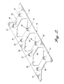
- FIGURE 2 provides more detail as to the specific construction of insert plate 16.
- Inserts 18 are cylindrical in shape with their axis being normal to insert plate 16 and frame 20. Thus, inserts 18 also extend generally perpendicular to snowboard 10 when placed therein. Inserts 18 include threaded bores 22 for receiving snowboard binding fasteners. Insert plate 16 may include two or more inserts projecting upwardly therefrom. Preferably, eight inserts are provided projecting from insert plate 16. Alternatively, inserts 18 could project downwardly from frame 20 of insert plate 16.
- Inserts 18 are integrally formed with frame 20, both preferably from a sheet of stainless steel.
- Frame 20 includes triangular anchors 24 surrounding the base of inserts 18.
- Triangular anchors 24 are significantly larger than the diameter of inserts 18. The surface area of triangular anchors 24 prohibits inserts 18 from being pulled from snowboard 10.
- Triangular anchors 24 are connected at their corners, one to another, to preferably provide two rows of inserts with four inserts 18 in each row. Fillets 26 make the transition from triangular anchors 24 to inserts 18.
- Inserts 18 are preferably stamped within insert plate 16 such that fillets 26 are formed during stamping.
- Insert plate 16 may alternatively be constructed from a material other than stainless steel. Another metal may be used or a composite material, for example.
- insert plate 16 is constructed from fiberglass reinforced plastic, preferably urethane.
- an insert plate mold is preferably used, such that the reinforced urethane (or other plastic such as nylon) is injected into the mold. The entire shape, including threads is preferably molded in this manner, such that the insert plate 16 would be ready for placement in the snowboard upon removal from the insert plate mold.
- This embodiment of the method provides an insert plate that is less expensive to manufacture, lighter in weight, and at least equally as strong. Since the threads are molded in no cutting is required. The uncut glass reinforcement produces strong threads.
- the other advantage to a molded insert plate 16 is that inserts 18 are preferably molded with closed bottoms. Thus, a machine screw for binding attachment cannot be accidentally inserted so far as to break through the bottom of snowboard 10. Furthermore, the closed bottom prohibits moisture from being channeled into the board.
- interconnection members 28 are also part of the same sheet of material that formed insert plate 16. Each of interconnection members 28 extend between two inserts 18.
- a generally ladder shaped insert plate 16 is provided with the rungs of the ladder corresponding to interconnection members 28 and the ladder rails corresponding to triangular anchors 24 connected, one to another, at their bases.
- apertures 30 are formed between interconnection members 28 and triangular anchors 24.
- apertures 30 are hexagonal in shape.
- insert plate 16 is lighter in weight than if this material was not removed to form apertures 30.
- frame 20 results with inserts 18 extending upwardly therefrom and being supported by frame 20 to resist both rotation and translation with respect to one another and with respect to snowboard 10. Since inserts 18 are simply stamped within insert plate 16, the manufacturing costs are low. Also, the accuracy of the placement of inserts 18 is assured by this method.
- insert plate 16 is generally rectangular. Alternatively, however, the plate may be round, oval, or any other shape as long as it provides support for at least two inserts used for securing a binding to a snowboard. Furthermore, apertures 30, anchors 24, and members 28 may have different configurations from those illustrated and described. Apertures 30 may be nonexistent in an alternate embodiment.
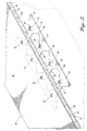
- FIGURE 3 illustrates the placement of insert plate 16 within snowboard 10.
- snowboard 10 includes a top 32, a base 34, and a wood core 36a.
- Top 32 is constructed of a top laminate 38 and a top reinforcement layer 40 joined beneath top laminate 38.
- Top laminate 38 is preferably a polyurethane.
- Top reinforcement layer 40 is preferably fiberglass.
- Base 34 is made up of a base laminate 42 and a base reinforcement layer 44.
- Base laminate 42 may be a urethane or a polyethylene. Other materials may alternatively be used.
- Wood core 36a is joined between top 32 and base 34.
- Other constructions, such as torsion box instead of laminate construction, may also be used with top 32, base 34 and core 36.
- insert plate 16 is disposed on top of base reinforcement layer 44.
- a recess is cut within wood core 36a for receiving insert plate 16, including frame 20 and inserts 18.
- insert plate 16 is placed within the cut recess of wood core 36a and joined between the recess of wood core 36a and base reinforcement layer 44.
- Inserts 18 extend upwardly into wood core 36a, preferably to the top of wood core 36a.
- Access holes 52 are cut within top 32, including top laminate 38 and top reinforcement layer 40, to provide access to threaded bores 22 of inserts 18.
- Wood core 36a is provided with the recess, preferably by using a milling machine, which precisely cuts wood core 36a into a recessed shape to matingly engage insert plate 16 and securely hold it therein in a precise position.
- Snowboard 10 may alternatively be constructed with a foam core or other core materials.
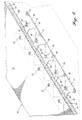
- FIGURE 4 illustrates snowboard 10 constructed with a foam core 36b. Other details of snowboard 10 in FIGURE 4 are essentially the same as those illustrated in FIGURE 3 and as discussed above.
- core 36b When used with a foam core, core 36b may be cut to provide a recess, as was done with wood core 36a, or foam core 36b may be injection molded between top 32 and base 34 after insert plate 16 has been placed between top 32 and base 34, as shown in FIGURE 5.
- FIGURE 4 also illustrates the use of insert plate 16 in a modular fashion with additional inserts 18 provided on a separate two-bore insert plate 46.
- Two-bore insert plate 46 is substantially the same as insert plate 16 except that it only includes two inserts.
- Two-bore insert plate 46 abuts the end triangular anchors 24 of insert plate 16 so as to provide a longer effective insert plate that includes two additional inserts 18 to provide ten inserts total.
- Two-bore insert plate 46 may alternatively be a four-bore insert plate or other numbers of inserts.
- insert plate 16 may include other number of inserts 18.
- standard or more common sizes of insert plates with common numbers of inserts 18 may be constructed and then abutted with additional insert plates 46 for alternative constructions with different numbers of inserts.
- This modular construction method maintains the low cost of the operation while still providing accurate placement and a secure hold on binding fasteners.
- Two-bore insert plate 46 is placed between top 32 and base 34 with insert plate 16 before foam core 36b is injected there
- FIGURES 5 and 6 illustrate the method of constructing a snowboard with insert plate 16 in a foam core snowboard and, in FIGURE 6, in a wood core snowboard. These cross-sectional views also illustrate the placement of steel edges 48 at the sides of base 34. Steel edges 48 are preferably the standard edges used in the industry.
- Side walls 50 are also shown. Side walls 50 are preferably constructed of ABS and extend from base 34 on top of steel edges 48 to top 32 such that a complete enclosure of core 36 is made. Alternatively, a cap-type top construction could be used in which top 32 extends not only over the top of core 36, but down the sides to meet with base 34 and steel edges 48.
- insert plate 16 may be placed externally over a torsion box reinforcement layer and still extend therethrough and into and through core 36.
- the method of constructing a foam core snowboard preferably includes the steps of joining the base reinforcement layer 44 to base laminate 42 and steel edges 48 to make the subassembly base 34.
- the subassembly top 32 is also separately constructed with top laminate 38 joined to the top reinforcement layer 40.
- Top 32, base 34 and side walls 50 are then placed within a mold with insert plate 16 precisely positioned on base reinforcement layer 44 beneath top 32.
- Insert plate 16 may be glued into place or otherwise attached in the proper location between top 32 and base 34. This attachment need only be temporary so as to withstand the next step of injecting foam between top 32 and base 34 to create foam core 36b.
- Foam core 36b then substantially envelopes insert plate 16 around the sides of inserts 18 and the top and sides of frame 20. The bottom of frame 20 remains against base 34, while the tops of inserts 18 remain against the bottom of top reinforcement layer 40.
- insert plate 16 may have frame 20 positioned adjacent top reinforcement layer 40 with inserts 18 projecting downwardly therefrom.
- foam core 36b securely holds insert plate 16 in place once cured.
- Access holes 52 are then drilled within top 32 to provide access to threaded bores 22 of insert plate 16.
- the method of construction with a wood core provides a similar end product, except that wood is being used instead of foam. However, the method is different since the wood core is obviously not injected into the snowboard. Instead, an insert plate recess 54 is milled into the bottom of wood core 36a to matingly engage insert plate 16. Access holes 52 may be drilled within top 32 prior to assembly or after assembly. The entire structure may be assembled while top reinforcement layer 40 and base reinforcement layer 44 are still wet, such that once cured. they bind the assembly together into a single unit comprising snowboard 10.
- insert plate 16 may be placed within insert plate recess 54 of wood core 36a prior to being wrapped with the torsion box, and the torsion box core insert plate assembly being placed between base 34, top 32 and side walls 50. Access holes 52 would then also extend through the portions of the torsion box directly above inserts 18 to provide access to threaded bores 22.
- inserts 18 are integrally formed or securely affixed to frame 20, they are not allowed to turn or move relative to the other inserts I S. The assembly process is quicker and thus more efficient.
- Insert plate 16 is also cost effective to construct from a sheet of stainless steel. Inserts 18 are stamped into the plate and then threaded. As mentioned above, the surface area of frame 20 will not allow any of the individual inserts to be pulled from snowboard 10, even with extreme upward pressure from the binding fasteners.
Landscapes
- Road Paving Structures (AREA)
- Cleaning Of Streets, Tracks, Or Beaches (AREA)
- Road Signs Or Road Markings (AREA)
- Footwear And Its Accessory, Manufacturing Method And Apparatuses (AREA)
- Fittings On The Vehicle Exterior For Carrying Loads, And Devices For Holding Or Mounting Articles (AREA)
Claims (34)
- Verfahren zur Konstruktion eines Laufgeräts, wie z. B. eines Skis oder Snowboards, das ein Unterteil (34), einen Kern (36) und ein Oberteil (32) aufweist, mit den Schrittena) Bereitstellung mehrerer miteinander verbundener Einsätze (18), an denen Bindungen befestigt werden können, wobei die Einsätze (18) durch einen Rahmen (20) aus Material miteinander verbunden sind und Löcher (22) aufweisen, die vom Rahmen (20) im Wesentlichen senkrecht nach oben ragen,b) Einbetten der Einsätze (18) im Kern (36) nach Anordnen der Einsätze (18) zwischen dem Unterteil (34) und dem Oberteil (32) an einer Position, an der Bindungen befestigt werden sollen, sowiec) Verbinden des Unterteils (34) und des Oberteils (32) mit dem Kern (36).
- Verfahren nach Anspruch 1, bei dem die Einsätze (18) mit einer Einsatzplatte (16), die einen im Wesentlichen planen Abschnitt aufweist, verbunden werden.
- Verfahren nach Anspruch 2, bei dem die Einsatzplatte (16) aus einem einzigen Werkstück, in dem die Einsätze (18) gebildet werden, hergestellt wird.
- Verfahren nach Anspruch 3, bei dem die Einsatzplatte aus einer Metallplatte hergestellt wird, wobei zuerst die Einsätze (18) in die Metallplatte eingeprägt werden und dann die Innengewinde (22) in die Einsätze (18) geschnitten werden.
- Verfahren nach Anspruch 4, bei dem die Einsatzplatte (16) Öffnungen (30) aufweist, wobei um diese Öffnungen (30) herum ein Metallrahmen zum Halten und Verbinden der Einsätze (18) verbleibt.
- Verfahren nach Anspruch 3, das weiterhin die Bildung der Einsatzplatte (16) aus einem Kunststoff-Verbundwerkstoff umfasst, wobei gleichzeitig die Einsätze (18) gebildet werden.
- Verfahren nach Anspruch 6, bei dem die Einsatzplatte (16) durch Spritzgießen gebildet wird und die Innengewinde (22) während des Spritzgießens in die Einsätze (18) eingeformt werden.
- Verfahren nach Anspruch 7, bei dem die Einsatzplatte (16) aus glasfaserverstärktem Urethan gebildet wird.
- Verfahren nach Anspruch 2, bei dem es sich bei der Einsatzplatte (16) um einen Rahmen handelt, der die Einsätze (18) miteinander verbindet.
- Verfahren nach Anspruch 2, bei dem die Einsätze (18) vom planen Abschnitt nach oben ragen, wobei der plane Abschnitt im Wesentlichen flach auf dem Unterteil (34) positioniert wird.
- Verfahren nach Anspruch 10, bei dem der Kern (36) einen Schaumkern umfasst und das Beschichten der Einsatzplatte (16) mit dem Kern (36) das Einspritzen von Schaum zwischen dem Unterteil (34) und dem Oberteil (32), nachdem dazwischen die Einsatzplatte (16) angeordnet wurde, umfasst, wobei der Schaum den Raum zwischen dem Unterteil (34) und dem Oberteil (32) füllt und die Einsatzplatte (16) einhüllt.
- Verfahren nach Anspruch 2, bei dem der Kern (36) einen Schaumkern umfasst und das Beschichten der Einsatzplatte (16) mit dem Kern (36) das Einspritzen von Schaum zwischen dem Unterteil (34) und dem Oberteil (32), nachdem dazwischen die Einsatzplatte (16) angeordnet wurde, umfasst, wobei der Schaum den Raum zwischen dem Unterteil (34) und dem Oberteil (32) füllt und die Einsatzplatte (16) einhüllt.
- Verfahren nach Anspruch 12, das weiterhin die Bildung von Löchern (52) im Oberteil (32) direkt über den Einsätzen (18) umfasst, damit Schrauben durch das Oberteil (32) in die Einsätze (18) ragen können.
- Verfahren nach Anspruch 2, bei dem das Unterteil (34) und das Oberteil (32) in den äußeren Schichten (38, 42) ein Gefügeverstärkungsmaterial umfassen, wobei der Kern (36) zwischen dem Gefügeverstärkungsmaterial des Oberteils (32) und Unterteils (34) eingefügt wird.
- Verfahren nach Anspruch 2, bei dem der Kern (36) Holz umfasst, und das Verfahren weiterhin das Schneiden einer Vertiefung (54) in den Kern (36) umfasst, die der Form der Einsatzplatte (16) angepasst ist, so dass die Einsatzplatte (16) einen festen Sitz in dieser Vertiefung (54) hat, wenn sie mit dem Kern (36) beschichtet ist.
- Verfahren nach Anspruch 1, bei dem die Einsätze (18) aus einem Metallblech gebildet werden, wobei die Einsätze (18) in das Metallblech eingeprägt werden und das Blech den Rahmen (20) bildet, der die Einsätze (18) in Bezug aufeinander fixiert.
- Verfahren nach Anspruch 1, bei dem die Einsätze (18) vom sie verbindenden Rahmen (20) nach oben ragen und der Rahmen (20) in der Nähe des Unterteils angeordnet wird.
- Verfahren nach Anspruch 1, bei dem in dem Materialblech zwischen den Einsätzen (18) Öffnungen (30) gebildet werden.
- Verfahren nach Anspruch 1, bei dem der Kern (36) aus Schaum gebildet und zwischen dem Oberteil (32) und dem Unterteil (34) eingespritzt wird, nachdem dazwischen die Einsätze (18) angeordnet wurden, so dass der Kern (36) die Einsätze (18) und den sie verbindenden Rahmen (20) einhüllt.
- Verfahren nach Anspruch 16, bei dem der Kern (36) aus Holz gebildet wird, und das Verfahren weiterhin die Bildung einer Vertiefung (54) im Holzkern umfasst, die der Form der Einsätze (18) und des sie verbindenden Rahmens (20) angepasst ist, um in ihr die Einsätze (18) und den Rahmen (20) einzusetzen.
- Verfahren nach Anspruch 1, bei dem der Kern (36) aus Schaum gebildet und zwischen dem Oberteil (32) und dem Unterteil (34) eingespritzt wird, nachdem dazwischen die Einsätze (18) angeordnet wurden, so dass der Kern (36) die Einsätze (18) und den sie verbindenden Rahmen (20) einhüllt.
- Verfahren nach Anspruch 1, bei dem der Kern (36) aus Holz gebildet wird, und das Verfahren weiterhin die Bildung einer Vertiefung (54) im Holzkern umfasst, die der Form der Einsätze (18) und des sie verbindenden Rahmens (20) angepasst ist, um in ihr die Einsätze (18) und den Rahmen (20) einzusetzen.
- Verfahren nach Anspruch 1, das weiterhin die Bildung von Löchern (52) im Oberteil (32) direkt über den Einsätzen (18) umfasst, um an diesen eine Bindung zu befestigen.
- Verfahren nach Anspruch 1, das weiterhin die Anordnung zusätzlicher miteinander verbundener Einsätze neben den miteinander verbundenen Einsätzen im Kern zwischen dem Unterteil und dem Oberteil umfasst, um zusätzliche Stellen für die Anbringung der Schrauben der Bindung zu schaffen.
- Verfahren nach Anspruch 1, das weiterhin die Bildung der Einsätze (18) und des Rahmens (20) durch Spritzgießen einer Einsatzplatte, die den Rahmen und die angeformten Einsätze umfasst, umfasst, wobei die Platte aus einem Kunststoff-Verbundwerkstoff gebildet wird.
- Verfahren nach Anspruch 25, bei dem der Kern (36) aus Schaum gebildet und zwischen dem Oberteil (32) und dem Unterteil (34) eingespritzt wird, nachdem dazwischen die Einsatzplatte (16) angeordnet wurde, so dass der Kern (36) die Einsätze (18) und den sie verbindenden Rahmen (20) einhüllt.
- Verfahren nach Anspruch 25, bei dem der Kern (36) aus Holz gebildet wird, und das Verfahren weiterhin die Bildung einer Vertiefung (54) im Holzkern umfasst, die der Form der Einsatzplatte angepasst ist, um in ihr die Einsatzplatte einzusetzen.
- Gerät, wie z. B. ein Ski oder ein Snowboard, zum Gleiten über eine Fläche, mita) einem Unterteil (34), das eine Lauffläche bildet,b) einem Oberteil (32), das über dem Unterteil (34) angeordnet ist, undc) einem Kern (36), der zwischen dem Unterteil (34) und dem Oberteil (32) angeordnet ist,
gekennzeichnet durchd) mehrere Einsätze (18), die vom Kern (36) eingehüllt und zwischen dem Unterteil (34) und dem Oberteil (32) angeordnet sind und nach oben ragende Löcher (22) zur Aufnahme von Schrauben für die Befestigung einer Bindung aufweisen, sowiee) einen Rahmen (20), der die Einsätze (18) miteinander verbindet und in Bezug aufeinander fixiert. - Gerät nach Anspruch 28, bei dem die Einsätze (18) und der Rahmen (20) in einem Stück gebildet sind, wobei die Einsätze (18) und der Rahmen (20) ein Metallblech (16) umfassen und die Einsätze (18) von einem im Wesentlichen planen Abschnitt des Metallblechs (16) nach außen ragen.
- Gerät nach Anspruch 29, bei dem die Einsätze (18) Innengewinde zur Aufnahme von Schrauben umfassen.
- Gerät nach Anspruch 29, bei dem der Rahmen (20) Rahmenelemente (28) mit sich dazwischen befindenden Öffnungen (30) umfasst, wobei die Rahmenelemente (28) die Einsätze (18) miteinander verbinden.
- Gerät nach Anspruch 31, bei dem der Kern (36) Schaum umfasst und im Wesentlichen die Seiten der Einsätze (18) sowie mindestens eine Seite des Rahmens (20) umgibt.
- Gerät nach Anspruch 31, bei dem der Kern (36) Holz umfasst und eine Vertiefung zur exakten Aufnahme der Einsätze (18) und des Rahmens (20) aufweist.
- Gerät nach Anspruch 29, bei dem der plane Abschnitt des Blechs (16) in der Nähe des Unterteils angeordnet ist und die Einsätze (18) von diesem durch den Kern (36) hindurch nach oben ragen.
Applications Claiming Priority (3)
| Application Number | Priority Date | Filing Date | Title |
|---|---|---|---|
| US573017 | 1995-12-15 | ||
| US08/573,017 US5863050A (en) | 1995-12-15 | 1995-12-15 | Snowboard insert plate |
| PCT/US1996/019770 WO1997022391A1 (en) | 1995-12-15 | 1996-12-10 | Snowboard insert plate |
Publications (2)
| Publication Number | Publication Date |
|---|---|
| EP0869832A1 EP0869832A1 (de) | 1998-10-14 |
| EP0869832B1 true EP0869832B1 (de) | 2002-03-27 |
Family
ID=24290311
Family Applications (1)
| Application Number | Title | Priority Date | Filing Date |
|---|---|---|---|
| EP96944323A Expired - Lifetime EP0869832B1 (de) | 1995-12-15 | 1996-12-10 | Snowboard-einlegeplatte |
Country Status (7)
| Country | Link |
|---|---|
| US (1) | US5863050A (de) |
| EP (1) | EP0869832B1 (de) |
| AT (1) | ATE214960T1 (de) |
| AU (1) | AU703518B2 (de) |
| DE (1) | DE69620234T2 (de) |
| NZ (1) | NZ325612A (de) |
| WO (1) | WO1997022391A1 (de) |
Cited By (1)
| Publication number | Priority date | Publication date | Assignee | Title |
|---|---|---|---|---|
| WO2016060390A1 (ko) * | 2014-10-15 | 2016-04-21 | 주식회사 경동스포츠 | 스키플레이트 조립체 및 그 제조방법 |
Families Citing this family (9)
| Publication number | Priority date | Publication date | Assignee | Title |
|---|---|---|---|---|
| EP0852157A3 (de) * | 1997-01-04 | 1999-03-31 | Franz Völkl GmbH & Co. Ski und Tennis Sportartikelfabrik KG | Gleitbrett, insbesondere Snowboard sowie Verankerungssystem zur Befestigung einer Bindung oder dergleichen Funktionselement an einem Gleitbrett |
| US6234513B1 (en) | 1997-01-31 | 2001-05-22 | James S. Busby, Jr. | Snowboard drive system |
| US6105991A (en) | 1997-11-20 | 2000-08-22 | The Burton Corporation | Core for a gliding board |
| US6502850B1 (en) | 1999-10-12 | 2003-01-07 | The Burton Corporation | Core for a gliding board |
| US20020185840A1 (en) | 2001-06-06 | 2002-12-12 | Schaller Hubert M. | Binding mounting method and apparatus |
| ATE486641T1 (de) * | 2002-09-24 | 2010-11-15 | Tyrolia Technology Gmbh | Gleitbrett, insbesondere ski, und verfahren zur herstellung |
| DE202004004304U1 (de) * | 2004-03-18 | 2004-05-13 | Tyrolia Technology Gmbh | Gleitbrett, insbesondere Ski |
| US7347431B2 (en) * | 2004-09-09 | 2008-03-25 | Chomp, Inc. | Skateboard deck construction |
| US20080079238A1 (en) * | 2006-09-22 | 2008-04-03 | John Geisler | Snowboard with mechanically attached snow or ice removal elements and foot rest |
Family Cites Families (21)
| Publication number | Priority date | Publication date | Assignee | Title |
|---|---|---|---|---|
| US2384729A (en) * | 1944-03-18 | 1945-09-11 | North American Aviation Inc | Floating nut |
| US2395650A (en) * | 1944-04-25 | 1946-02-26 | Camloe Fastener Corp | Fastener construction |
| US2526137A (en) * | 1948-05-24 | 1950-10-17 | Everett M Hunt | Ski |
| AT214326B (de) * | 1959-02-27 | 1961-03-27 | Michael Ober | Halteplatte für Schibindungen |
| FR1282053A (fr) * | 1960-12-06 | 1962-01-19 | Skis composites | |
| DE1923367A1 (de) * | 1969-05-07 | 1970-11-19 | Max Waxenberger | Verbundski |
| US3722901A (en) * | 1970-02-14 | 1973-03-27 | Nippon Musical Instruments Mfg | Ski having a hard type foamed resin core |
| US3917299A (en) * | 1974-09-30 | 1975-11-04 | Peter F Anderson | Fastener for ski bindings |
| FR2431868A1 (fr) * | 1978-07-28 | 1980-02-22 | Look Sa | Ski muni d'inserts d'ancrage d'une fixation de securite |
| AT355965B (de) * | 1978-08-28 | 1980-04-10 | Tyrolia Freizeitgeraete | Ski mit einem elektrisch bzw. elektronisch aus- loesbaren signal |
| DE2913250A1 (de) * | 1979-04-03 | 1980-10-23 | Schneeco Oskar Schneegans Poly | Hartschaum-ski |
| DE58903268D1 (en) * | 1988-08-11 | 1993-02-25 | Tyrolia Freizeitgeraete | Ski. |
| US5096217A (en) * | 1988-12-01 | 1992-03-17 | Kent Hunter | Monoski with deep side cuts and cambered segment in the binding portion |
| AT393224B (de) * | 1990-02-08 | 1991-09-10 | Tyrolia Freizeitgeraete | Ski |
| AT394142B (de) * | 1990-09-14 | 1992-02-10 | Tyrolia Freizeitgeraete | Ski |
| AT395113B (de) * | 1990-12-14 | 1992-09-25 | Tyrolia Freizeitgeraete | Ski |
| WO1992022361A1 (en) * | 1991-06-17 | 1992-12-23 | Trimble & Co., Inc. | Ski binding block |
| US5320378A (en) * | 1991-09-05 | 1994-06-14 | Wiig Jeffrey R | Snowboard |
| CA2089313A1 (en) * | 1993-02-11 | 1994-08-12 | Randy Jespersen | Boot binding system for a snowboard |
| FR2703916B1 (fr) * | 1993-04-16 | 1995-05-19 | Rossignol Sa | Ski comportant des chants et une coque supérieure. |
| US5419665A (en) * | 1994-04-01 | 1995-05-30 | Tiodize Company, Inc. | Non-metallic nut ring |
-
1995
- 1995-12-15 US US08/573,017 patent/US5863050A/en not_active Expired - Lifetime
-
1996
- 1996-12-10 AT AT96944323T patent/ATE214960T1/de not_active IP Right Cessation
- 1996-12-10 DE DE69620234T patent/DE69620234T2/de not_active Expired - Lifetime
- 1996-12-10 AU AU12877/97A patent/AU703518B2/en not_active Ceased
- 1996-12-10 NZ NZ325612A patent/NZ325612A/xx unknown
- 1996-12-10 EP EP96944323A patent/EP0869832B1/de not_active Expired - Lifetime
- 1996-12-10 WO PCT/US1996/019770 patent/WO1997022391A1/en not_active Ceased
Cited By (1)
| Publication number | Priority date | Publication date | Assignee | Title |
|---|---|---|---|---|
| WO2016060390A1 (ko) * | 2014-10-15 | 2016-04-21 | 주식회사 경동스포츠 | 스키플레이트 조립체 및 그 제조방법 |
Also Published As
| Publication number | Publication date |
|---|---|
| DE69620234D1 (de) | 2002-05-02 |
| US5863050A (en) | 1999-01-26 |
| ATE214960T1 (de) | 2002-04-15 |
| NZ325612A (en) | 1998-12-23 |
| EP0869832A1 (de) | 1998-10-14 |
| AU1287797A (en) | 1997-07-14 |
| DE69620234T2 (de) | 2002-07-18 |
| AU703518B2 (en) | 1999-03-25 |
| WO1997022391A1 (en) | 1997-06-26 |
Similar Documents
| Publication | Publication Date | Title |
|---|---|---|
| US5863050A (en) | Snowboard insert plate | |
| CA2164158C (en) | Snowboard binding mounting system | |
| US5232241A (en) | Snow ski with integral binding isolation mounting plate | |
| US6612605B2 (en) | Integrated modular glide board | |
| EP1137461B1 (de) | Kern für gleitbrett | |
| US5016901A (en) | Ski | |
| WO1997022391A9 (en) | Snowboard insert plate | |
| US7967324B2 (en) | Cross-country ski assembly and cross-country ski binding | |
| JP3053608U (ja) | 滑走ボード用のコア | |
| EP1222007B1 (de) | Snowboard mit partieler seitenwand | |
| WO1997046436A1 (en) | Articulated two-section snowboard | |
| US20060175802A1 (en) | Snowboard impact plate and binding release mechanism | |
| CA1179386A (en) | Water ski construction | |
| WO2005056131A1 (en) | Gliding board with vibration-absorbing layer | |
| US5839747A (en) | Binding anchor | |
| US7497460B2 (en) | Sliding board, particularly a ski | |
| US7416207B2 (en) | Sliding board, particularly a ski, and a method for the production thereof | |
| US5655786A (en) | Snowboard assemblies, fasteners, and related methods | |
| US20100019463A1 (en) | Gliding or rolling board | |
| US20050121881A1 (en) | Ski core | |
| US20070187926A1 (en) | Interface device for a gliding board, a gliding apparatus including such device, and a method of manufacture | |
| WO1997026958A1 (en) | Binding anchor | |
| US20090045605A1 (en) | Snow ski |
Legal Events
| Date | Code | Title | Description |
|---|---|---|---|
| PUAI | Public reference made under article 153(3) epc to a published international application that has entered the european phase |
Free format text: ORIGINAL CODE: 0009012 |
|
| 17P | Request for examination filed |
Effective date: 19980608 |
|
| AK | Designated contracting states |
Kind code of ref document: A1 Designated state(s): AT BE CH DE DK ES FI FR GB GR IE IT LI LU MC NL PT SE |
|
| 17Q | First examination report despatched |
Effective date: 20000808 |
|
| GRAG | Despatch of communication of intention to grant |
Free format text: ORIGINAL CODE: EPIDOS AGRA |
|
| GRAG | Despatch of communication of intention to grant |
Free format text: ORIGINAL CODE: EPIDOS AGRA |
|
| GRAH | Despatch of communication of intention to grant a patent |
Free format text: ORIGINAL CODE: EPIDOS IGRA |
|
| GRAH | Despatch of communication of intention to grant a patent |
Free format text: ORIGINAL CODE: EPIDOS IGRA |
|
| REG | Reference to a national code |
Ref country code: GB Ref legal event code: IF02 |
|
| GRAA | (expected) grant |
Free format text: ORIGINAL CODE: 0009210 |
|
| AK | Designated contracting states |
Kind code of ref document: B1 Designated state(s): AT BE CH DE DK ES FI FR GB GR IE IT LI LU MC NL PT SE |
|
| PG25 | Lapsed in a contracting state [announced via postgrant information from national office to epo] |
Ref country code: NL Free format text: LAPSE BECAUSE OF FAILURE TO SUBMIT A TRANSLATION OF THE DESCRIPTION OR TO PAY THE FEE WITHIN THE PRESCRIBED TIME-LIMIT Effective date: 20020327 Ref country code: IT Free format text: LAPSE BECAUSE OF FAILURE TO SUBMIT A TRANSLATION OF THE DESCRIPTION OR TO PAY THE FEE WITHIN THE PRESCRIBED TIME-LIMIT;WARNING: LAPSES OF ITALIAN PATENTS WITH EFFECTIVE DATE BEFORE 2007 MAY HAVE OCCURRED AT ANY TIME BEFORE 2007. THE CORRECT EFFECTIVE DATE MAY BE DIFFERENT FROM THE ONE RECORDED. Effective date: 20020327 Ref country code: GR Free format text: LAPSE BECAUSE OF FAILURE TO SUBMIT A TRANSLATION OF THE DESCRIPTION OR TO PAY THE FEE WITHIN THE PRESCRIBED TIME-LIMIT Effective date: 20020327 Ref country code: FI Free format text: LAPSE BECAUSE OF FAILURE TO SUBMIT A TRANSLATION OF THE DESCRIPTION OR TO PAY THE FEE WITHIN THE PRESCRIBED TIME-LIMIT Effective date: 20020327 Ref country code: BE Free format text: LAPSE BECAUSE OF FAILURE TO SUBMIT A TRANSLATION OF THE DESCRIPTION OR TO PAY THE FEE WITHIN THE PRESCRIBED TIME-LIMIT Effective date: 20020327 Ref country code: AT Free format text: LAPSE BECAUSE OF FAILURE TO SUBMIT A TRANSLATION OF THE DESCRIPTION OR TO PAY THE FEE WITHIN THE PRESCRIBED TIME-LIMIT Effective date: 20020327 |
|
| REF | Corresponds to: |
Ref document number: 214960 Country of ref document: AT Date of ref document: 20020415 Kind code of ref document: T |
|
| REG | Reference to a national code |
Ref country code: CH Ref legal event code: EP |
|
| REG | Reference to a national code |
Ref country code: CH Ref legal event code: NV Representative=s name: ISLER & PEDRAZZINI AG |
|
| REF | Corresponds to: |
Ref document number: 69620234 Country of ref document: DE Date of ref document: 20020502 |
|
| REG | Reference to a national code |
Ref country code: IE Ref legal event code: FG4D |
|
| PG25 | Lapsed in a contracting state [announced via postgrant information from national office to epo] |
Ref country code: SE Free format text: LAPSE BECAUSE OF FAILURE TO SUBMIT A TRANSLATION OF THE DESCRIPTION OR TO PAY THE FEE WITHIN THE PRESCRIBED TIME-LIMIT Effective date: 20020627 Ref country code: PT Free format text: LAPSE BECAUSE OF FAILURE TO SUBMIT A TRANSLATION OF THE DESCRIPTION OR TO PAY THE FEE WITHIN THE PRESCRIBED TIME-LIMIT Effective date: 20020627 Ref country code: DK Free format text: LAPSE BECAUSE OF FAILURE TO SUBMIT A TRANSLATION OF THE DESCRIPTION OR TO PAY THE FEE WITHIN THE PRESCRIBED TIME-LIMIT Effective date: 20020627 |
|
| ET | Fr: translation filed | ||
| NLV1 | Nl: lapsed or annulled due to failure to fulfill the requirements of art. 29p and 29m of the patents act | ||
| PG25 | Lapsed in a contracting state [announced via postgrant information from national office to epo] |
Ref country code: ES Free format text: LAPSE BECAUSE OF FAILURE TO SUBMIT A TRANSLATION OF THE DESCRIPTION OR TO PAY THE FEE WITHIN THE PRESCRIBED TIME-LIMIT Effective date: 20020925 |
|
| PG25 | Lapsed in a contracting state [announced via postgrant information from national office to epo] |
Ref country code: LU Free format text: LAPSE BECAUSE OF NON-PAYMENT OF DUE FEES Effective date: 20021210 Ref country code: IE Free format text: LAPSE BECAUSE OF NON-PAYMENT OF DUE FEES Effective date: 20021210 Ref country code: GB Free format text: LAPSE BECAUSE OF NON-PAYMENT OF DUE FEES Effective date: 20021210 |
|
| PLBE | No opposition filed within time limit |
Free format text: ORIGINAL CODE: 0009261 |
|
| STAA | Information on the status of an ep patent application or granted ep patent |
Free format text: STATUS: NO OPPOSITION FILED WITHIN TIME LIMIT |
|
| 26N | No opposition filed |
Effective date: 20021230 |
|
| PG25 | Lapsed in a contracting state [announced via postgrant information from national office to epo] |
Ref country code: MC Free format text: LAPSE BECAUSE OF NON-PAYMENT OF DUE FEES Effective date: 20030701 |
|
| GBPC | Gb: european patent ceased through non-payment of renewal fee | ||
| REG | Reference to a national code |
Ref country code: IE Ref legal event code: MM4A |
|
| REG | Reference to a national code |
Ref country code: CH Ref legal event code: PCAR Free format text: ISLER & PEDRAZZINI AG;POSTFACH 1772;8027 ZUERICH (CH) |
|
| PGFP | Annual fee paid to national office [announced via postgrant information from national office to epo] |
Ref country code: CH Payment date: 20111227 Year of fee payment: 16 Ref country code: FR Payment date: 20120104 Year of fee payment: 16 |
|
| PGFP | Annual fee paid to national office [announced via postgrant information from national office to epo] |
Ref country code: DE Payment date: 20111229 Year of fee payment: 16 |
|
| REG | Reference to a national code |
Ref country code: CH Ref legal event code: PL |
|
| REG | Reference to a national code |
Ref country code: FR Ref legal event code: ST Effective date: 20130830 |
|
| REG | Reference to a national code |
Ref country code: DE Ref legal event code: R119 Ref document number: 69620234 Country of ref document: DE Effective date: 20130702 |
|
| PG25 | Lapsed in a contracting state [announced via postgrant information from national office to epo] |
Ref country code: DE Free format text: LAPSE BECAUSE OF NON-PAYMENT OF DUE FEES Effective date: 20130702 Ref country code: LI Free format text: LAPSE BECAUSE OF NON-PAYMENT OF DUE FEES Effective date: 20121231 Ref country code: CH Free format text: LAPSE BECAUSE OF NON-PAYMENT OF DUE FEES Effective date: 20121231 |
|
| PG25 | Lapsed in a contracting state [announced via postgrant information from national office to epo] |
Ref country code: FR Free format text: LAPSE BECAUSE OF NON-PAYMENT OF DUE FEES Effective date: 20130102 |