EP0868662B1 - Micromachined ion permeable composite membranes for amperometric ion detection - Google Patents
Micromachined ion permeable composite membranes for amperometric ion detection Download PDFInfo
- Publication number
- EP0868662B1 EP0868662B1 EP96942502A EP96942502A EP0868662B1 EP 0868662 B1 EP0868662 B1 EP 0868662B1 EP 96942502 A EP96942502 A EP 96942502A EP 96942502 A EP96942502 A EP 96942502A EP 0868662 B1 EP0868662 B1 EP 0868662B1
- Authority
- EP
- European Patent Office
- Prior art keywords
- composite membrane
- micromachined
- ion
- permeable composite
- membrane according
- Prior art date
- Legal status (The legal status is an assumption and is not a legal conclusion. Google has not performed a legal analysis and makes no representation as to the accuracy of the status listed.)
- Expired - Lifetime
Links
Images




Classifications
-
- G—PHYSICS
- G01—MEASURING; TESTING
- G01N—INVESTIGATING OR ANALYSING MATERIALS BY DETERMINING THEIR CHEMICAL OR PHYSICAL PROPERTIES
- G01N27/00—Investigating or analysing materials by the use of electric, electrochemical, or magnetic means
- G01N27/26—Investigating or analysing materials by the use of electric, electrochemical, or magnetic means by investigating electrochemical variables; by using electrolysis or electrophoresis
- G01N27/28—Electrolytic cell components
- G01N27/40—Semi-permeable membranes or partitions
Definitions
- This invention relates to micromachined ion permeable composite membranes for the amperometric detection and quantitation of ionic species. Detection systems of the invention are applied to flow analysis and disposable ion sensing devices in clinical diagnostics and heavy metal analysis.
- ion sensing membranes and transducers in the form of glass membranes and organic polymer membranes have been the major electrochemical routes for the potentiometric analysis of non-redox ionic species [1].
- One common type of potentiometric probe is the glass pH electrode, which incorporates thin glass membranes, and which is used for monitoring the concentration of H + ions.
- Other membranes have been developed for a wide range of monovalent cations.
- the glass membranes can optionally be modified by the inclusion of hydrophobic layers to design electrodes which can specifically detect gases such as CO 2 or NH 3 [2].
- Amperometric ion measurement techniques have several advantages over the traditional potentiometric methods.
- the measurement of a current signal (as a result of an ion or electron transfer process or reaction at a polarised interface between immiscible liquids) is directly proportional to the concentration of the analyte under study, and the current-time response characteristics are often of the order of seconds.
- Sensing probes consisting of interfaces between two immiscible liquids or between a liquid and a gel can for example be used for the amperometric monitoring of ion concentrations. Ion transfer processes and reactions through such interfaces are diffusion controlled and as such all the electroanalytical methodology developed for solid electrodes can be directly applied [3].
- the interface formed with aqueous solutions and viscous hydrophobic gel materials have, for example, been used in ion sensing experiments.
- the inherent poor electrical conductivity combined with the poor mechanical stability of these gel formulations has thus far restricted their use in experimental and sensor design [3-6].
- Efforts to reduce the resistivity and to improve the mechanical stability of the gel materials have been made.
- resistivities have been diminished by inclusion in the gel solvent of high concentrations of ionic substances such as organic electrolytes.
- the high electrical resistances associated with the aforementioned gels remain, and consequently influence the form and quantitative value of the electroanalytical signal (measured signal is visibly distorted by the effects of the large 5 ohmic drop).
- the reliable identification and determination of ionic species by the principle of ion transfer at polarised polymeric interfaces thus requires the development of a novel approach to membrane design in order to alleviate the aforementioned limitations.
- the invention therefore provides, in one aspect, a micromachined ion permeable composite membrane comprising: a non-polarisable layer having at least one microaperture formed therethrough; and an electrically polarisable material comprising a polymer matrix, into which a predetermined ionic species is capable of entering, the polarisable material being disposed in relation to said at least one microaperture so as to provide a passageway of well defined cross-sectional area for said predetermined ionic spieces through the interface between the composite membrane and a sample with which the membrane is placed in contact.
- membrane structure into specific and well-defined geometric patterns may be achieved for example by UV laser photoablation or chemical etching procedures, which in effect expose parts of the polarisable material (i.e. plasticised polymer or organic gel) of the composite membrane.
- polarisable material i.e. plasticised polymer or organic gel
- Such composite membranes have a number of possible applications in disposable ion sensing systems, flow injection analysis systems and immunochromatographic systems [7-10].
- the incorporation of such composite membranes according to the invention in a probe-like assembly, in a similar manner to a potentiometric ISE could lead to a marketable amperometric version of an ISE probe for a number 5 of ion transferable species of interest in clinical diagnosis.
- an "ion transferable” species is herein defined as an ionic substance which moves from one liquid or gel phase to another by virtue of an applied electrical potential difference across the interfacial region.
- the transfer phenomenon is by its nature potential specific and as such introduces a high degree of selectivity to the ion sensing system.
- the response characteristics of the ion permeable composite membranes of the invention as analytical transducers to determine ionic concentrations have proved to be superior to those previously described, in terms of specificity, sensitivity, limit of detection, speed of response, accuracy and precision.
- the sensing component of the invention i.e. the polarisable material
- the sensing component of the invention can detect and quantitate metal and molecular ions by the principle of ion transfer from the sample into the polarisable material by electric polarisation.
- Ion transfer currents generated by this movement of ionic species can be measured by the composite membrane transducer and are only very weakly influenced by the composite membrane resistance effects, thus significantly reducing the applied signal distortions and improving the measurement characteristics.
- Chemical transducers and devices consisting of the composite membranes as sensing components exhibit a high degree of selectivity for complex samples.
- the device signal for the detection of cations remains unaffected by the presence of potentially interfering urate and ascorbate ions in clinical samples (e.g. whole blood, diluted blood fractions, serum and plasma), even when these ions are present at concentrations as high as 700 ⁇ M.
- clinical samples e.g. whole blood, diluted blood fractions, serum and plasma
- the ionic response of the composite membrane i.e. the ion transfer current
- the ion transfer currents flow with diffusion control and are extremely well defined because the diffusion fields are generated by the specific micromachining of the non-polarisable layer.
- This precision machined microstructure yields constant currents for a given analyte concentration in electroanalytical techniques such as cyclic voltammetry and chronoamperometry.
- This unique diffusion field characteristic [7-10] ultimately gives the composite membrane transducer fast signal response times where the measured responses possess high signal to noise ratios.
- the measured signals manifest themselves as steady state voltammetric or amperometric waves, which offer several important advantages for analytical determination of ionic substances.
- micromachined apertures of the illustrated embodiment are arranged in regular arrays of micro circular holes or discs. It should be stressed that other geometries are also applicable to the invention, where one of the dimensions lies on the micrometer scale, for example microsquare, microhexagon, microstrip or microband, etc.
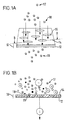
- Figure 1A is a perspective schematic view of an embodiment of micromachined ion permeable composite membrane according to the invention, wherein the reference numerals indicate: (17) water phase or sample, (18) ion transferable species, (16) micro-interfacial region, (14) non-polarisable layer, (12) polarisable layer, (19) transferred ionic species, (10) micromachined ion permeable composite membrane.
- Figure 1B is a sectional schematic view, taken along line B-B of Figure 1A; wherein the reference numerals indicate: (17) water phase, (14) non-polarisable layer, (12) polarisable layer, (18) ion transferable species, (20) depiction of, for example, cationic transfer from a water phase to the polarisable layer, (10) micromachined ion permeable composite membrane.
- Figure 2 is a scanning electron micrograph showing the micro aperture array of an embodiment of composite membrane of the same general type as that illustrated in Figures 1A and 1B.
- Figure 3 is a sectional schematic view of an embodiment of micromachined ion permeable composite membrane similar to that shown in Figure 1B, but having an immobilised enzyme layer, wherein the reference numerals indicate: (18) the sample, (12) polarisable layer, (22) immobilised enzyme, (24) depiction of the enzyme reaction showing the production of an ion transferable species from a non-transferable or non-interfering chemical species, (20) depiction of ionic transfer as in Figure 1.
- Figure 4 is a sectional schematic view of an embodiment of micromachined ion permeable composite membrane similar to that shown in Figure 1B, but having an immobilised immunochemical reagent layer, wherein the reference numerals indicate: (18) the sample, (12) polarisable layer, (26) immobilised immunochemical reagent such as an antibody, an antibody fragment or an antigenic entity or substance, (28) depiction of an enzyme marker reaction showing the production of an ion transferable species from a non-transferable or non-interfering chemical species, (20) depiction of ionic transfer as in Figure 1.
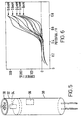
- Figure 5 is a perspective diagrammatic view of an embodiment of probe sensor incorporating a micromachined ion permeable composite membrane according to the invention, wherein the reference numerals indicate: (30) the ion permeable composite membrane, (32) replaceable tip holding the composite membrane, (34) internal probe compartment holding a reference electrode and internal electrolyte solution or gel, (36) external reference electrode, (38) body of the probe sensor.
- Figure 6 is a series of cyclic voltammograms obtained from the transfer of choline across an embodiment of ion permeable composite membrane according to the invention, (This figure clearly demonstrates the advantages of the present invention over the response of devices with large interfaces as shown in Figure 5 of reference [6].
- the invention provides improvements in ohmic polarisation and measurement precision with greatly reduced background currents.).
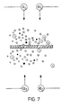
- Figure 7 is a sectional schematic view of an embodiment of micromachined ion permeable composite membrane similar to that shown in Figure 1B, and illustrates an ion sensing arrangement wherein the composite membrane of the invention lies between two electrolyte compartments (aqueous or otherwise) holding separate reference electrodes RE1 and RE2 respectively and current measuring electrodes CE1 and CE2 respectively.
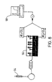
- Figure 8 is a schematic view of the embodiment of composite membrane shown in Figures 1 to 5, used as the detection system in a flow analysis apparatus, in which the reference numerals indicate: (54) injector, (56) detector, and (58) electrochemical workstation.
- Figures 9A and 9B are, respectively, a plan view and a side view of an embodiment of disposable sensor incorporating a composite membrane of the type illustrated in Figures 1 to 5 as part of the detection system.
- the embodiment shown comprises an immunochromatography strip, wherein the reference numerals indicate: (40) immunochromatography strip, (42) sample window with enzyme conjugate, (44) a transfer membrane containing assays reagents, (46) detector region, (48) non-polarisable layer, (50) reference electrode such as printed silver-silver chloride ink film for the polarisable layer, (52) reference electrode such as printed silver-silver chloride ink film for the sample solution.
- Figure 10 is a schematic sectional view of an embodiment of membrane according to the invention, in which the polarisable layer (60) does not fill the apertures in the non-polarisable layer (62).
- Figure 11 is a schematic sectional view of an embodiment of membrane according to the invention, corresponding to Figure 10, but in which the non-polarisable layer is covered by a protective layer (64).
- Figure 12 is a schematic sectional view of a further embodiment of membrane according to the invention, in which the non-polarisable layer (66) is embedded within the polarisable layer (68).
- Figure 13 is a schematic sectional view of a yet further alternative embodiment of membrane according to the invention, in which an electrically conductive layer (70) is disposed between the polarisable (72) and non-polarisable (74) layers.
- micromachined ion permeable composite membrane 10 is composed of hydrophobic ion-sensitive layer 12 and hydrophilic non-polarisable layer 14.
- An array of U.V. excimer machined micro-pores 16 is formed in non-polarisable layer 14 (see also Figure 2), to reveal portions of the underlying ion-sensitive layer 12.
- the ionic analyte of interest 18 moves towards the composite membrane 10 as a result of interfacial polarisation of the membrane with respect to the sample solution, and diffusion of the ions through the exposed portions of the ion polarisable layer 16 gives rise to a measurable and well defined amperometric signal ( i ).
- the composite membranes may be manufactured by several fabrication routes.
- One such approach is the lamination of a non-polarisable film (for example a polyester) with a film of the polarisable material (such as a PVC composite).
- This layer can be applied as an extremely thin film with micrometer thicknesses, but because of the operational requirements of the micromachined composite membrane system it is not essential to have such high fabrication control over this film thickness.
- the polarisable layer may be applied over the complete surface of the non-polarisable layer, here referred to as the support material, or at selected sites thereon.
- Film-forming hydrophobic polymers can be used to make the polarisable layer and can be applied to the support material by several filming methods, for example extrusion coating, casting from solvents, spread filming, applying as gelled laminated film, spray coating, ink-jet printing or screen printing.
- the polarisable and non-polarisable laminate may then be subjected to a laser drilling or photolithographic etching process to open up apertures (either single apertures or an array of apertures) in the non-polarisable layer.
- the micromachining of the non-polarisable layer can be carried out prior to hydrophobic polymer lamination. This procedure exposes microscopic regions of the polarisable material and defines the chemical sensing geometry of the membrane.
- the non-polarisable material can be pre-conditioned or surface treated by laser hydrophilisation methods in order to alter the chemical character of the surface, for example to alter the hydrophilic state of the surface. These treatments are particularly preferred steps where biochemicals such as enzymes or antibodies are to be immobilised on the surface of the non-polarisable support.
- the micromachined non-polarisable layer may consist of a regular array of open regions in circular form, their size ranging from some 50nm to 500 ⁇ m in diameter. Arrays of such apertures may take the form of regular hexagons or squares, etc. Single open regions may also be utilised and in this case the opening would again range from 50nm to 500 ⁇ m in diameter.
- the open region or regions function as electrically polarisable interfaces through which ionic species transfer from the sample phase into the polarisable material. Definition of the film aperture geometries allows careful control of ion transfer flux into the composite membrane and hence the form and magnitude of the current response of the chemical sensors and detectors incorporating membranes according to the invention.
- the polarisable material preferably consists of a matrix polymer which may be solely hydrophobic or have at least a substantial degree of hydrophobicity.
- the polarisable materials also preferably contains a solvent with plasticising properties with low water miscibility and possessing low vapour pressure.
- One preferred formulation for the polarisable material comprises polyvinylchloride with o-nitrophenyloctylether as plasticiser or solvent and Bis(triphenylphosphoranylidene) ammonium tetrakis(4-chlorophenylborate) electrolytic species.
- the polarisable material should have good processability, in particular the ability to adhere well to the non-polarisable layer and the ability to form stable films on that layer.
- the material should have a sensitive and rapid response to selected ions in a sample, with good stability over the test lifetime.
- the non-polarisable support is preferably composed of a polymeric film-forming material with adequate mechanical stability, low water absorption characteristics and excellent insulating properties. Such materials are usually less than 100 ⁇ m in film thickness, and function as an electrically insulating surface. A wide range of commercially available film plastics with varying degrees of surface hydrophobic character may be used. Poly(ethylene terephthalate) is a suitable film material, possessing very good laser machining properties and high volume resistivity. Its excellent adherence to laminated materials allows it to be chemically functionalised and amenable to UV laser surface texturing and hydrophilisation.
- Film compositions may vary depending on the processing conditions (for example whether they are formed by means of thermal, IR or UV curing procedures).
- Polystyrenes can be used for example to form a thin film covering over the hydroghobic layer: for example a formulation consisting of polystyrene dissolved in isophorone and applied to a surface by the methods of extrusion coating, casting from solvents, spread filming, spray coating, ink-jet printing or screen printing and cured at low temperature forms a film with excellent dielectric and UV photoablative properties.
- the formulation for the non-polarisable material may include one or more chemical reagents in order to provide a specific chemical sensor function, for example, sensors for clinical diagnostic testing.
- Such reagents may include enzyme substrates or enzymes.
- enzymes such as urease, creatinine deiminase, glutamate dehydrogenase or phenylalanine deaminase, etc. could be incorporated as part of or attached to the non-polarisable polymer component in order to provide specific clinical tests for urea, creatinine, glutamate or phenylalanine respectively.
- a composite membrane with bound enzymes is shown schematically in Figure 3 for the analysis of enzyme substrates.
- the enzymes 22 are bound to the non-polarisable layer and the enzyme-catalysed reaction producing the species to be detected is indicated by reference numeral 24.
- the enzymes could be added to the test sample, for example as a dry reagent.
- the system could also be arranged for the analysis of enzyme concentrations where the substrate of a target enzyme is added to the test sample as a dry reagent and the enzyme quantitated by the production of selective ion transferable species.
- Illustrated in figure 4 is a composite membrane functionalised with antibody reagents, which is suitable for use in immunochemical reactions and analysis.
- Antibodies 26 bound to the non-polarisable layer capture antigen-enzyme conjugates.
- the captured enzyme undergoes reaction 28, producing the species to be detected.
- Affinity composite membranes of this type may be used for example in enzyme immunoassays with flow instrumentation.
- FIG. 5 is a diagrammatic representation of the features of a typical probe, in which the composite membrane 30 is contained in a replaceable tip connector 32. Internal electrolyte (gel or solution) is added to the recess between the composite membrane 34 and a suitable internal reference electrode. An external reference electrode 36 is also fitted and positioned on an exposed region on the external surface of the main body of the probe 38, so as to come into contact with a sample into which the probe is placed.
- gel or solution Internal electrolyte
- An external reference electrode 36 is also fitted and positioned on an exposed region on the external surface of the main body of the probe 38, so as to come into contact with a sample into which the probe is placed.
- the polarisable layer overlies the non-polarisable layer, and also substantially fills the apertures in the non-polarisable layer.
- this geometry has been found to perform well in tests, it is by no means essential, and may readily be varied according to the requirements of the individual application for which the membrane is intended, and/or of the manufacturing process. For example, it may in a number of cases be more convenient to manufacture a membrane in which the apertured non-polarisable layer simply overlies the polarisable layer, and the polarisable layer does not extend into the apertures to any substantial extent.
- Such an arrangement is illustrated in Figure 10.
- the non-polarisable layer may be covered by a protective layer, for example of an aqueous gel, to inhibit membrane fouling and improve sensor performance in flow systems (see Figure 11).
- a protective layer for example of an aqueous gel, to inhibit membrane fouling and improve sensor performance in flow systems (see Figure 11).
- Preferred aqueous gels include polyacrylamide, polyvinylalcohol and hydroxyethylcellulose.
- Figure 12 A yet further alternative is illustrated in Figure 12, in which the polarisable material passes through the apertures to cover both sides of the non-polarisable layer, so that the non-polarisable layer is effectively embedded within the polarisable layer.
- the thickness of the polarisable layer on the sample side of the polarisable layer should be less than the characteristic diameter of the microapertures, in order to avoid distortions to the well defined current flow provided by the presence of the microapertures.
- Figure 13 illustates an arrangement in which the non-polarisable layer is coated with a metallic layer (for example of gold, platinum or silver), so as to act either as a counter electrode (as indicated by CE2 in Figure 7), or as a reference electrode (as indicated by RE2 in Figure 7).
- the material of the coating is preferably anodised silver, for example AgCl, AgSO 4 or silver tetraphenylborate.
- the composite membranes of the invention are likely to have wide applications in clinical diagnostics. They may be designed to sense many species of clinical and environmental interest: polarisable membrane formulations are envisaged for K + -responsive membranes, Na + -responsive membrane, Ca 2+ -responsive membranes, Cl - -responsive membranes, NH 4 + -responsive membranes, Pb 2+ -responsive membranes, Cd 2+ -responsive membranes, Zn 2+ -responsive membranes and Cu 2+ -responsive membranes, among others.
- Ion sensing agents such crown ethers, heterocyclic antibiotics, carbazone ligands (eg valinomycin for K + ) and diphenylcarbazone (for Pb 2+ and other heavy metals) may be incorporated into the ion sensitive layer, depending on the analyte of interest.
- Figure 6 depicts a voltammogram obtained from a composite membrane used to sense and quantitate choline.
- Electrochemical sensors can be constructed from composite membranes according to the invention for the detection and quantification of a wide range of blood analytes, which exhibit diminished blood matrix interferences of the type commonly encountered with conventional amperometric devices.
Landscapes
- Chemical & Material Sciences (AREA)
- Life Sciences & Earth Sciences (AREA)
- Health & Medical Sciences (AREA)
- Physics & Mathematics (AREA)
- Chemical Kinetics & Catalysis (AREA)
- Electrochemistry (AREA)
- Molecular Biology (AREA)
- Analytical Chemistry (AREA)
- Biochemistry (AREA)
- General Health & Medical Sciences (AREA)
- General Physics & Mathematics (AREA)
- Immunology (AREA)
- Pathology (AREA)
- Investigating Or Analyzing Non-Biological Materials By The Use Of Chemical Means (AREA)
- Apparatus Associated With Microorganisms And Enzymes (AREA)
Description
Claims (24)
- A micromachined ion permeable composite membrane (10; 30) comprising: a non-polarisable layer (14; 62; 66; 74) having at least one microaperature formed there through; and an electrically polarisable material (12, 16; 60; 68; 72) comprising a polymer matrix, into which a predetermined ionic species (18) is capable of entering, the polarisable material being disposed in relation to said at least one microaperature so as to provide a passageway of well defined cross-sectional area for said predetermined ionic species through the interface between the composite membrane and a sample (17) with which the membrane is placed in contact.
- A micromachined ion permeable composite membrane according to claim 1, wherein the polymer matrix is substantially hydrophobic in nature.
- A micromachined ion permeable composite membrane according to claim 2, wherein the polymer matrix is of poly(vinyl chloride).
- A micromachined ion permeable composite membrane according to any preceding claim, wherein the polarisable material comprises an organic solvent.
- A micromachined ion permeable composite membrane according to claim 4, wherein the solvent is sparingly soluble in water, typically less than 5% in weight.
- A micromachined ion permeable composite membrane according to claim 5, wherein the solvent is o-nitrophenyloctyl ether.
- A micromachined ion permeable composite membrane according to any preceding claim, wherein the polarisable material comprises a hydrophobic electrolytic substance.
- A micromachined ion permeable composite membrane according to claim 7, wherein the hydrophobic electrolytic substance is Bis(triphenylphosphoranylidene) ammonium tetrakis (4-chlorophenylborate).
- A micromachined ion permeable composite membrane according to any preceding claim, wherein the polarisable material further comprises an ion-complexing phase transfer species.
- A micromachined ion permeable composite membrane according to claim 9, wherein the ion complexing phase transfer species is a ligand capable of complexation with a target ion within the sample and driving the target ion into the polarisable part of the composite membrane.
- A micromachined ion permeable composite membrane according to claim 10, wherein the non polarisable material is a polyester (e.g. poly (ethylene terephthalate) ) or a vinyl polymer (e.g. polystyrene).
- A micromachined ion permeable composite membrane according to any preceding claim, wherein the non-polarisable layer is subjected to laser hydophilisation.
- A micromachined ion permeable composite membrane according to any preceding claim, wherein enzymes or antibodies (22; 26) are attached to the non-polarisable layer in the vicinity of the at least one micro aperture.
- A micromachined ion permeable composite membrane according to any preceding claim, wherein said at least one micro aperture is formed by laser photoablation.
- A micromachined ion permeable composite membrane according to any preceding claim, wherein the membrane possesses a single micro aperture, having a diameter of less than 500µm and more than 50nm.
- A micromachined ion permeable composite membrane according to any of claims 1 to 15, wherein the membrane possesses an array of micro apertures.
- A micromachined ion permeable composite membrane according to claim 16, wherein each micro aperture has a diameter of less than 500µm and more than 50nm.
- An ion detector comprising a micromachined ion permeable composite membrane according to any preceding claim, wherein polarisation is achieved by two electrodes (RE1,RE2), one placed on each side of the membrane, the mode of detection being amperometric monitoring of the ion flux through the microaperture.
- An ion detector according to claim 18, for use in flow injection analysis and/or chromatography.
- A disposable ion detection apparatus comprising a micromachined ion permeable composite membrane according to any of claims 1 to 17, the membrane being directly mounted on a support arrangement.
- An ammonia sensor comprising a micromachined ion permeable composite membrane according to any of claims 1 to 17, the membrane being covered by an ion-free hydrophilic layer and a gas permeable membrane, e.g. Teflon (poly(tetrafluoroethylene)).
- A sensor as claimed in 21 for use in detecting urea and/or creatinine.
- A micromachined ion permeable composite membrane according to any of claims 1 to 17, wherein the polarisable material comprises enzymes, enzyme substrates, enzyme cofactors or the like (22).
- A heavy metal ion sensor comprising: a micromachined ion permeable composite membrane according to any of claims 1 to 17; or an ion detector according to claim 18 or claim 19.
Applications Claiming Priority (3)
| Application Number | Priority Date | Filing Date | Title |
|---|---|---|---|
| GBGB9525921.4A GB9525921D0 (en) | 1995-12-19 | 1995-12-19 | Micromachined ion permeable composite membranes for amperometric ion detection |
| GB9525921 | 1995-12-19 | ||
| PCT/GB1996/003149 WO1997022875A1 (en) | 1995-12-19 | 1996-12-19 | Micromachined ion permeable composite membranes for amperometric ion detection |
Publications (2)
| Publication Number | Publication Date |
|---|---|
| EP0868662A1 EP0868662A1 (en) | 1998-10-07 |
| EP0868662B1 true EP0868662B1 (en) | 2003-03-12 |
Family
ID=10785670
Family Applications (1)
| Application Number | Title | Priority Date | Filing Date |
|---|---|---|---|
| EP96942502A Expired - Lifetime EP0868662B1 (en) | 1995-12-19 | 1996-12-19 | Micromachined ion permeable composite membranes for amperometric ion detection |
Country Status (5)
| Country | Link |
|---|---|
| EP (1) | EP0868662B1 (en) |
| JP (1) | JP2001501724A (en) |
| DE (1) | DE69626673D1 (en) |
| GB (1) | GB9525921D0 (en) |
| WO (1) | WO1997022875A1 (en) |
Cited By (3)
| Publication number | Priority date | Publication date | Assignee | Title |
|---|---|---|---|---|
| WO2018046527A1 (en) | 2016-09-09 | 2018-03-15 | Robert Bosch Gmbh | Selective amperometric measurement of non-electroactive cations by means of a disposable test strip |
| WO2018046404A1 (en) | 2016-09-09 | 2018-03-15 | Robert Bosch Gmbh | Discardable test strip for multiple home blood analyte test |
| WO2022268894A1 (en) * | 2021-06-22 | 2022-12-29 | Prominent Gmbh | Closure device for a measurement chamber of an electrochemical sensor |
Families Citing this family (17)
| Publication number | Priority date | Publication date | Assignee | Title |
|---|---|---|---|---|
| DE19628928A1 (en) | 1996-07-18 | 1998-01-22 | Basf Ag | Solid supports for analytical measurement processes, a process for their production and their use |
| GB9624686D0 (en) * | 1996-11-27 | 1997-01-15 | Cole Polytechnique Fudurale De | Surface patterning of affinity reagents |
| US7244349B2 (en) | 1997-12-17 | 2007-07-17 | Molecular Devices Corporation | Multiaperture sample positioning and analysis system |
| US20020144905A1 (en) | 1997-12-17 | 2002-10-10 | Christian Schmidt | Sample positioning and analysis system |
| WO1999039829A1 (en) | 1998-02-04 | 1999-08-12 | Merck & Co., Inc. | Virtual wells for use in high throughput screening assays |
| US6139831A (en) * | 1998-05-28 | 2000-10-31 | The Rockfeller University | Apparatus and method for immobilizing molecules onto a substrate |
| WO1999066322A1 (en) * | 1998-06-15 | 1999-12-23 | Biosensor Systems Design, Inc. (1998) | A sensor for analyte detection |
| US6322963B1 (en) | 1998-06-15 | 2001-11-27 | Biosensor Systems Design., Inc. | Sensor for analyte detection |
| US6342347B1 (en) | 1999-10-22 | 2002-01-29 | Biosensor Systems Design., Inc. | Electromagnetic sensor |
| US6503701B1 (en) | 1999-06-15 | 2003-01-07 | Biosensor Systems Design, Inc. | Analytic sensor apparatus and method |
| US6662439B1 (en) * | 1999-10-04 | 2003-12-16 | Roche Diagnostics Corporation | Laser defined features for patterned laminates and electrodes |
| DE10014667C1 (en) * | 2000-03-24 | 2001-10-18 | Envitec Wismar Gmbh | Process for the production of gas diffusion membranes by partial laser evaporation |
| US7067046B2 (en) | 2000-08-04 | 2006-06-27 | Essen Instruments, Inc. | System for rapid chemical activation in high-throughput electrophysiological measurements |
| US7270730B2 (en) | 2000-08-04 | 2007-09-18 | Essen Instruments, Inc. | High-throughput electrophysiological measurement system |
| DE10340429A1 (en) * | 2003-09-02 | 2005-04-07 | GESELLSCHAFT FüR BIOTECHNOLOGISCHE FORSCHUNG MBH (GBF) | Hydrophobic object with a pattern of hydrophilic areas, its production and use |
| FR2872290A1 (en) * | 2004-06-24 | 2005-12-30 | Commissariat Energie Atomique | METHOD OF HIGHLY PARALLEL ANALYSIS OF ENZYMATIC REACTIONS AND ITS APPLICATIONS |
| CN105784800A (en) * | 2016-04-28 | 2016-07-20 | 无锡昊瑜节能环保设备有限公司 | Intelligent monitoring system for heavy metal content of industrial water quality |
Family Cites Families (2)
| Publication number | Priority date | Publication date | Assignee | Title |
|---|---|---|---|---|
| EP0103031B1 (en) * | 1982-09-03 | 1986-05-07 | Dräger Nederland B.V. | Electro-chemical cell for determining a particular property or component of a fluid |
| US4484987A (en) * | 1983-05-19 | 1984-11-27 | The Regents Of The University Of California | Method and membrane applicable to implantable sensor |
-
1995
- 1995-12-19 GB GBGB9525921.4A patent/GB9525921D0/en active Pending
-
1996
- 1996-12-19 JP JP09522589A patent/JP2001501724A/en active Pending
- 1996-12-19 WO PCT/GB1996/003149 patent/WO1997022875A1/en not_active Ceased
- 1996-12-19 DE DE69626673T patent/DE69626673D1/en not_active Expired - Lifetime
- 1996-12-19 EP EP96942502A patent/EP0868662B1/en not_active Expired - Lifetime
Cited By (5)
| Publication number | Priority date | Publication date | Assignee | Title |
|---|---|---|---|---|
| WO2018046527A1 (en) | 2016-09-09 | 2018-03-15 | Robert Bosch Gmbh | Selective amperometric measurement of non-electroactive cations by means of a disposable test strip |
| WO2018046404A1 (en) | 2016-09-09 | 2018-03-15 | Robert Bosch Gmbh | Discardable test strip for multiple home blood analyte test |
| DE102016217261A1 (en) | 2016-09-09 | 2018-03-15 | Robert Bosch Gmbh | Selective amperometric measurement of non-electroactive cations and disposable test strips |
| DE102016217257A1 (en) | 2016-09-09 | 2018-03-15 | Robert Bosch Gmbh | Disposable test strips for multiple home blood analyzer test |
| WO2022268894A1 (en) * | 2021-06-22 | 2022-12-29 | Prominent Gmbh | Closure device for a measurement chamber of an electrochemical sensor |
Also Published As
| Publication number | Publication date |
|---|---|
| DE69626673D1 (en) | 2003-04-17 |
| EP0868662A1 (en) | 1998-10-07 |
| JP2001501724A (en) | 2001-02-06 |
| WO1997022875A1 (en) | 1997-06-26 |
| GB9525921D0 (en) | 1996-02-21 |
Similar Documents
| Publication | Publication Date | Title |
|---|---|---|
| EP0868662A1 (en) | Micromachined ion permeable composite membranes for amperometric ion detection | |
| US4874500A (en) | Microelectrochemical sensor and sensor array | |
| Mohamed | Screen-printed disposable electrodes: Pharmaceutical applications and recent developments | |
| Suzuki et al. | An integrated three-electrode system with a micromachined liquid-junction Ag/AgCl reference electrode | |
| EP0608872B1 (en) | Current-detecting type dryoperative ion-selective electrode | |
| Kim et al. | Evaluation of nitrate and potassium ion-selective membranes for soil macronutrient sensing | |
| Brett et al. | Electrochemical sensing in solution—origins, applications and future perspectives | |
| CA2489535A1 (en) | Microfabricated sensor arrays | |
| EP0603742B1 (en) | Potentiometric ion determinations using enhanced selectivity asymmetric ion-selective membrane electrodes | |
| Mahmoud et al. | Design of solid‐contact ion‐selective electrode with graphene transducer layer for the determination of flavoxate hydrochloride in dosage form and in spiked human plasma | |
| Bartoszewicz et al. | Calibration free solid contact electrodes with two PVC based membranes | |
| Paczosa-Bator et al. | Potentiometric sensor platform based on a carbon black modified electrodes | |
| Abo‐bakr et al. | An efficient Novel electrochemical sensor for simultaneous determination of vitamin C and Aspirin based on a PMR/Zn‐Al LDH/GCE | |
| Kamel et al. | Screen‐printed electrochemical sensors for label‐free potentiometric and impedimetric detection of human serum albumin | |
| Xu et al. | Ion channel mimetic chronopotentiometric polymeric membrane ion sensor for surface confined protein detection | |
| AU639005B2 (en) | Electrochemical cell, reference electrode and electrochemical method | |
| US7625469B1 (en) | Nanoelectrode array for electrochemical analysis | |
| Ertürün et al. | A calix [4] arene derivative-doped perchlorate-selective membrane electrodes with/without multi-walled carbon nanotubes | |
| ANZAI et al. | Urea sensor based on an ion-sensitive field effect transistor. IV. Determination of urea in human blood | |
| EP0138150A2 (en) | Diagnostic electrode membranes utilizing specific enzyme/Ionophore pairs | |
| KR20200003008A (en) | Biosensors Produced from Enzymes with Reduced Solubility and Methods for Producing and Using Them | |
| EP0683390A1 (en) | Current detection type ion selective electrode | |
| Lynch et al. | Solid‐State Ion‐Selective Electrode Arrays | |
| Chang et al. | Healthcare chip based on integrated electrochemical sensors used for clinical diagnostics of BUN | |
| Brainina | Electroanalysis: From laboratory to field versions |
Legal Events
| Date | Code | Title | Description |
|---|---|---|---|
| PUAI | Public reference made under article 153(3) epc to a published international application that has entered the european phase |
Free format text: ORIGINAL CODE: 0009012 |
|
| 17P | Request for examination filed |
Effective date: 19980619 |
|
| AK | Designated contracting states |
Kind code of ref document: A1 Designated state(s): CH DE FR GB LI |
|
| 17Q | First examination report despatched |
Effective date: 20010509 |
|
| GRAH | Despatch of communication of intention to grant a patent |
Free format text: ORIGINAL CODE: EPIDOS IGRA |
|
| GRAH | Despatch of communication of intention to grant a patent |
Free format text: ORIGINAL CODE: EPIDOS IGRA |
|
| GRAA | (expected) grant |
Free format text: ORIGINAL CODE: 0009210 |
|
| AK | Designated contracting states |
Designated state(s): CH DE FR GB LI |
|
| PG25 | Lapsed in a contracting state [announced via postgrant information from national office to epo] |
Ref country code: LI Free format text: LAPSE BECAUSE OF FAILURE TO SUBMIT A TRANSLATION OF THE DESCRIPTION OR TO PAY THE FEE WITHIN THE PRESCRIBED TIME-LIMIT Effective date: 20030312 Ref country code: FR Free format text: LAPSE BECAUSE OF FAILURE TO SUBMIT A TRANSLATION OF THE DESCRIPTION OR TO PAY THE FEE WITHIN THE PRESCRIBED TIME-LIMIT Effective date: 20030312 Ref country code: CH Free format text: LAPSE BECAUSE OF FAILURE TO SUBMIT A TRANSLATION OF THE DESCRIPTION OR TO PAY THE FEE WITHIN THE PRESCRIBED TIME-LIMIT Effective date: 20030312 |
|
| REG | Reference to a national code |
Ref country code: GB Ref legal event code: FG4D |
|
| REG | Reference to a national code |
Ref country code: CH Ref legal event code: EP |
|
| REF | Corresponds to: |
Ref document number: 69626673 Country of ref document: DE Date of ref document: 20030417 Kind code of ref document: P |
|
| PG25 | Lapsed in a contracting state [announced via postgrant information from national office to epo] |
Ref country code: DE Free format text: LAPSE BECAUSE OF FAILURE TO SUBMIT A TRANSLATION OF THE DESCRIPTION OR TO PAY THE FEE WITHIN THE PRESCRIBED TIME-LIMIT Effective date: 20030613 |
|
| REG | Reference to a national code |
Ref country code: CH Ref legal event code: PL |
|
| PGFP | Annual fee paid to national office [announced via postgrant information from national office to epo] |
Ref country code: GB Payment date: 20031223 Year of fee payment: 8 |
|
| PLBE | No opposition filed within time limit |
Free format text: ORIGINAL CODE: 0009261 |
|
| STAA | Information on the status of an ep patent application or granted ep patent |
Free format text: STATUS: NO OPPOSITION FILED WITHIN TIME LIMIT |
|
| EN | Fr: translation not filed | ||
| 26N | No opposition filed |
Effective date: 20031215 |
|
| PG25 | Lapsed in a contracting state [announced via postgrant information from national office to epo] |
Ref country code: GB Free format text: LAPSE BECAUSE OF NON-PAYMENT OF DUE FEES Effective date: 20041219 |
|
| GBPC | Gb: european patent ceased through non-payment of renewal fee |
Effective date: 20041219 |