EP0868346B1 - Method and apparatus for filling bulk material - Google Patents
Method and apparatus for filling bulk material Download PDFInfo
- Publication number
- EP0868346B1 EP0868346B1 EP96939348A EP96939348A EP0868346B1 EP 0868346 B1 EP0868346 B1 EP 0868346B1 EP 96939348 A EP96939348 A EP 96939348A EP 96939348 A EP96939348 A EP 96939348A EP 0868346 B1 EP0868346 B1 EP 0868346B1
- Authority
- EP
- European Patent Office
- Prior art keywords
- filling
- opening
- bulk material
- weight
- closing
- Prior art date
- Legal status (The legal status is an assumption and is not a legal conclusion. Google has not performed a legal analysis and makes no representation as to the accuracy of the status listed.)
- Expired - Lifetime
Links
- 239000013590 bulk material Substances 0.000 title claims description 51
- 238000000034 method Methods 0.000 title claims description 10
- 230000007246 mechanism Effects 0.000 claims description 24
- 230000003213 activating effect Effects 0.000 claims description 11
- 230000009471 action Effects 0.000 claims description 6
- 239000000843 powder Substances 0.000 description 89
- 230000008859 change Effects 0.000 description 17
- 230000014509 gene expression Effects 0.000 description 15
- 230000003449 preventive effect Effects 0.000 description 5
- 238000006748 scratching Methods 0.000 description 4
- 230000002393 scratching effect Effects 0.000 description 4
- 230000001133 acceleration Effects 0.000 description 3
- 238000004364 calculation method Methods 0.000 description 3
- 238000010586 diagram Methods 0.000 description 3
- 230000006870 function Effects 0.000 description 3
- 239000002245 particle Substances 0.000 description 3
- 238000010276 construction Methods 0.000 description 2
- 230000002708 enhancing effect Effects 0.000 description 2
- 230000005484 gravity Effects 0.000 description 2
- 239000000463 material Substances 0.000 description 2
- 238000005070 sampling Methods 0.000 description 2
- 238000005429 filling process Methods 0.000 description 1
- 230000002035 prolonged effect Effects 0.000 description 1
- 230000004044 response Effects 0.000 description 1
- 238000007789 sealing Methods 0.000 description 1
Images





Classifications
-
- G—PHYSICS
- G01—MEASURING; TESTING
- G01G—WEIGHING
- G01G13/00—Weighing apparatus with automatic feed or discharge for weighing-out batches of material
- G01G13/24—Weighing mechanism control arrangements for automatic feed or discharge
-
- B—PERFORMING OPERATIONS; TRANSPORTING
- B65—CONVEYING; PACKING; STORING; HANDLING THIN OR FILAMENTARY MATERIAL
- B65B—MACHINES, APPARATUS OR DEVICES FOR, OR METHODS OF, PACKAGING ARTICLES OR MATERIALS; UNPACKING
- B65B1/00—Packaging fluent solid material, e.g. powders, granular or loose fibrous material, loose masses of small articles, in individual containers or receptacles, e.g. bags, sacks, boxes, cartons, cans, or jars
- B65B1/30—Devices or methods for controlling or determining the quantity or quality or the material fed or filled
- B65B1/32—Devices or methods for controlling or determining the quantity or quality or the material fed or filled by weighing
- B65B1/34—Adjusting weight by trickle feed
-
- G—PHYSICS
- G01—MEASURING; TESTING
- G01G—WEIGHING
- G01G13/00—Weighing apparatus with automatic feed or discharge for weighing-out batches of material
- G01G13/02—Means for automatically loading weigh pans or other receptacles, e.g. disposable containers, under control of the weighing mechanism
- G01G13/04—Means for automatically loading weigh pans or other receptacles, e.g. disposable containers, under control of the weighing mechanism involving dribble-feed means controlled by the weighing mechanism to top up the receptacle to the target weight
- G01G13/06—Means for automatically loading weigh pans or other receptacles, e.g. disposable containers, under control of the weighing mechanism involving dribble-feed means controlled by the weighing mechanism to top up the receptacle to the target weight wherein the main feed is effected by gravity from a hopper or chute
Definitions
- This invention relates to a method and an apparatus for filling bulk (powder and grain) material to a filling object such as a container and the like.
- JP-A Japanese Patent Application Laid-Open No.
- JP-A Japanese Patent Application Laid-Open No.
- JP-A Japanese Patent Application Laid-Open No. 52001/83
- the volume of bulk material is measured with a massive filling measure and its weight thereof is measured with a measuring device. Then, the bulk material is poured continuously in a small quantity through a small hole and when the poured amount reaches an objective filling value, the small hole is closed such that the filling operation is completed.
- the weight of a package product in which its filling of bulk material is completed is measured with a weight checker and the tendency in the supply amount thereof from a cup measuring device is controlled.
- a bulk material surface detecting device is provided on the hopper and according to signals output from this detecting device, the amount of bulk material flowing into the hopper is adjusted.
- US 2 829 856 discloses a method and apparatus for filling bulk material in accordance with the preambles of claims 1 and 2, wherein the operation of filling is divided into a first and a second filling step.
- the apparatus used for performing said method comprises an analog control loop where the weight is continuously measured and the movement of a closing valve is accordingly controlled.
- DE 2013687 describes a method of filling bulk material into containers, wherein the filling process is divided into a first and a second step. Both filling steps are controlled according to an analog control loop, wherein the material flow is continuously reduced in response to the steadily measured weight.
- the opening/closing mechanism is opened to a predetermined opening degree and the bulk material can be filled to the filling object until the first stage objective filling weight is reached, the bulk material can be filled rapidly.
- the opening/closing mechanism is activated so as to close from the specified opening degree, and based on a closing travel distance of the opening/closing mechanism in a certain minute time interval and a filling weight of bulk material, a fluidity of the bulk material in such a minute time interval is calculated and measured, and further a closing travel distance and a closing travel speed of the opening/closing mechanism in a next minute time interval are calculated based on this fluidity so as to activate the opening/closing mechanism to close thereby filling the bulk material to the filling object.
- the opening degree of the opening/closing mechanism is controlled so as to determine the full closing timing of the opening/closing mechanism, therefore it is possible to reduce the amount (falling amount) of bulk material existing between the opening/closing mechanism and the filling object when the opening/closing mechanism is fully closed, thereby realizing a high precision filling.
- a rotary type filling apparatus 110 as shown in FIG. 1, a plurality of the containers C as an object to be filled are installed on a disc (second base 112). While this disc is rotated, bulk material such as powder is gradually filled into respective containers C.
- This rotary type filling apparatus 110 comprises a turn table 113 acting as a storage portion, filling hoppers 114, first base 111, second base 112, shutters 115 acting as an opening/closing device, an encoder 116 for detecting a travel distance of load cells 117 for detecting weights, and a control unit 118.
- the turn table 113, the first base 111 and the second base 112 are fixed to a rotating shaft 119.
- the rotating shaft 119 is communicated with a driving motor 120 through a first bevel gear 121 and a second bevel gear 122 which mesh with each other.
- the turn table 113, the first base 111 and the second base 112 are rotated synchronously by means of the driving motor 120.
- the turn table 113, the first base 111, the second base 112, the rotating shaft 119, the driving motor 120 and the like are constructed so as to be surrounded by a casing 123.
- the turn table 113 is capable of storing powder and has a plurality of the filling hoppers 114 disposed along the circumference thereof.
- the casing 123 has a powder supplying cylinder 124, from which powder is supplied into the turn table 113 and stored thereon.
- a plate 125 for suppressing flying of bulk material is provided under the powder supplying cylinder 124 to suppress flying of bulk material when supplying.
- a plurality of the filling hoppers 114 are disposed such that the outlet openings thereof can be opened and closed individually by a plurality of the shutters 115.
- shutter activating devices 128 for activating the shutters 115 are disposed on the first base 111.
- the shutter activating device 128 comprises an electric cylinder 129 driven by a servo motor and a motor driver 130.
- the motor driver 130 is activated by a command from the control unit 118 to drive the electric cylinder 129 thereby determining the opening degree of the shutter 115.
- the shutter 115 is capable of continuously adjusting the supply amount (filling weight) of powder to be filled into the container C from the filling hopper 114.
- the electric-driven cylinder 129 is equipped with the encoder 116 for detecting a travel distance X for the opening/closing operation of the shutter 115 and this detected value X is output to a control unit 118.
- the second base 112 has a plurality of the load cells 117 disposed at respective positions corresponding to each of the filling hoppers 114 and the shutters 115.
- the containers C are placed on the load cells 117.
- the filling weight W of powder to be filled into the container C is detected by the load cell 117 and such a detected value W is output to the control unit 118.
- the first base 111 has powder flying preventive plates 131 which surround the outlet of each of the filling hoppers 114 and each of the shutters 115 so as to prevent powder from flying and scattering when powder is thrown into the container C from the filling hopper 114 thereby enhancing scaling performance between the filling hopper 114 and the container C.
- the container C is mounted on a transportation conveyor 132 and transported thereby and the transportation pitch of the container C is adjusted by a pitch adjusting device 133. Then the container C is carried onto the load cell 117 of the second base 112 by means of a supplying side star wheel 134. After the container C is filled with powder, it is sent out from the load cell 117 of the second base 112 to the transportation conveyor 132 by means of the disfilling side star wheel 135.
- the control unit 118 controls the opening/closing operation of a shutter 115 through a shutter operating mechanism 128, determines the degree of the opening of the shutter 115 at real time and fills powder to a container C from a filling hopper 114.
- a travel distance X of the shutter 115 at an arbitrary time is input to the control unit 118 from the encoder 116 and further a powder filling weight W to the container C at an arbitrary time is input thereto from the load cell 117.
- This control unit 118 contains an objective filling amount Wp of powder to be filled into a single container, a predetermined ratio ⁇ of the first stage objective filling amount Wp 1 (described later) relative to this Wp, a linear approximation data L as shown in FIG.
- the ⁇ Q can be obtained from the filling weight W of powder measured by the load cell 117, the ⁇ S(X) can be obtained from the travel distance X of the shutter 115 measured by the encoder 116 and the ⁇ t has been preliminarily determined as a sampling interval.
- the fluidity U ⁇ of powder in this minute interval of time ⁇ t can be measured according to the following expression (3).
- U ⁇ ⁇ Q/( ⁇ S(X) x ⁇ t) If the ⁇ S(X) is eliminated using the above expressions (1), (2), the following expression can be obtained.
- X ⁇ Q/U ⁇ x ⁇ t ⁇ x F(S) As a result, the travel distance X of the shutter 115 can be obtained.
- the fluidity U ⁇ of powder varies depending on the size of the particles of bulk material, percentage of voids of the powder particles, the shape of the powder particles, specific gravity of the powder, temperature and humidity in the filling hopper 114, the powder flying preventive plate 131 and the container C, and friction of the walls of the filling hopper 114, the powder flying preventive plate 131, and the container C, and the flow condition of air in the filling hopper 114, the powder flying preventive plate 131 and the container C and the like.
- This fluidity U ⁇ of powder affects the accuracy in weight of powder to be filled when the powder is thrown into the container C from the filling hopper 114.
- control unit 118 executes filling of the first and second stages when filling of powder from the filling hopper 114 into the container C is started (step (1) in FIG. 7).
- the control unit 118 calculates a first stage objective filling weight Wp 1 from an objective filling weight Wp and the predetermined ratio ⁇ according to the expression (5) below (step (2)).
- Wp 1 Wp x ⁇
- the predetermined ratio ⁇ is, for example, 98%.
- the control unit 118 calculates a travel distance (specified opening degree) X 1 of the shutter 115 corresponding to the first stage objective filling weight Wp 1 from the linear approximation data L shown in FIG. 6 (step (3)) and moves the shutter 115 at a specified speed (for example, X 1 /1m/sec) up to a travel distance X 1 (step (4)) to fill powder at a massive flow rate into the container C.
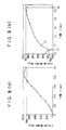
- the load cell 117 measures the filling weight W in the interval of the minute time ⁇ t (e.g. 10mmsec) as shown in FIG. 8(A) and this measured value W is entered into the control unit 118 (step (5)).
- the control unit 118 closes the shutter 115 from the specified opening degree X 1 so as to change over from the first stage filling to the second stage filling (step (6), (7)).
- This change-over time is first stage filling completion time and further second stage filling start up time. This change-over time is assumed to be t 1 .
- the control unit 118 calculates the second stage objective filling weight Wp 2 according to the expression below (6) (step (8)).
- Wp 2 W p - W(t 1 )
- the control unit 118 sets the travel distance X (t 2 ) for the closing operation of the shutter 115 in order to move the shutter 115 from this time t 1 to next time t 2 which is ahead by the minute time ⁇ t and the travel speed V(t 2 ) of the shutter 115 as follows:
- the reason why the measured value of the load cell 117 drops at time t 1 as shown in FIGs. 8(a) and 8(b) is due to an influence of the acceleration applied to powder at the first stage filling and that the measured value of the load cell 117 indicates a higher value than an actual filling weight.
- the control unit 118 calculates the closing travel distance X(t n+1 ) and travel speed V(t n+1 ) of the shutter 115 to be moved in an interval of minute time ⁇ t from time t n to next time t n+1 using the expression (4) according to the following expression;
- X(t n+1 ) [ ⁇ Wp 2 -(W(t n )-W(t 1 ) ⁇ /U ⁇ (t n ) x ⁇ t) x
- F(S) V(t n+1 ) X(t n+1 )/t
- the turn table 113 and the first base 111 and the second base 112 make a single turn in 4 seconds and the weight of the container C carried to the load cell 117 of the second base 112 from the supplying side star wheel 134 is detected by the load cell 117 in the first 0.2 seconds.
- filling at the first stage from the filling hopper 114 to the container C is conducted such that rapid filling at a massive filling rate is achieved.
- filling at the second stage from the filling hopper 114 to the container C is conducted such that a high precision filling at a minute filling rate is achieved.
- the container C in which powder is fully filled is carried out to the transportation conveyor 132 by means of the disfilling side star wheel 135 in 0.24 seconds and in the next 0.56 seconds, no container C is placed on the load cell 117.
- the shutter 115 is opened up to a specified opening degree X 1 at the first stage filling such that the powder can be massively filled into the container C up to its first stage objective filling weight Wp 1 , the powder can be filled rapidly.
- the shutter 115 is activated so as to be closed from its specified opening degree X 1 .
- the fluidity U ⁇ of bulk material in the interval of that minute time ⁇ t is calculated at real time.
- the closing travel distance X and the closing travel speed V of the shutter 115 in a next interval of minute time ⁇ t are calculated and the shutter 115 is closed such that the filling is completed.
- the opening degree of the shutter 115 is controlled so as to determine the full closing timing of the shutter 115.
- a rotary type filling apparatus 210 as shown in FIG. 9, which is not claimed, a plurality of the containers C as an object to be filled are installed on a disc (second base 212). While this disc is rotated, bulk material such as powder is gradually filled into respective containers C.
- This rotary type filling apparatus 210 comprises a turn table 213 acting as a storage portion, filling hoppers 214, a first base 211, the second base 212, shutters 215 acting as an opening/closing device, load cells 217 for detecting weights, and a control unit 218.
- the turn table 213, the first base 211 and the second base 212 are fixed to a rotating shaft 219.
- This rotating shaft 219 is communicated with a driving motor 220 through a first bevel gear 221 and a second bevel gear 222 which mesh with each other.
- the turn table 213, the first base 211 and the second base 212 are rotated synchronously by means of the driving motor 220.
- the turn table 213, the first base 211, the second base 212, the rotating shaft 219, the driving motor 220 and the like are constructed so as to be surrounded by a casing 223.
- the turn table 213 is capable of storing powder and has a plurality of the filling hoppers 214 disposed along the circumference thereof.
- the casing 223 has a powder supplying cylinder 224, from which powder is supplied into the turn table 213 and stored thereon.
- shutter activating devices 228 for activating the shutters 215 are disposed on the first base 211.
- This shutter activating device 228 comprises an electric cylinder 229 driven by a servo motor and a motor driver 230.
- This motor driver 230 is activated by a command from the control unit 218 to drive the electric cylinder 229 thereby determining the opening degree of the shutter 215.
- this shutter 215 is capable of adjusting continuously the supply amount (filling weight) of powder to be filled into the container C from the filling hopper 214. That is, the control unit 218 controls so as to supply a specified initial filling amount of powder massively with the shutter 215 opened at a massive opening degree at the massive throw-in stage, and then supply a remaining filling amount thereof at a small flow rate at the small throw-in stage thereby completing a filling of an objective filling weight (W 0 ) of powder in the container C.
- the second base 212 has a plurality of the load cells 217 disposed at respective positions corresponding to each of the filling hoppers 214 and the shutters 215.
- the containers C are placed on the load cells 217.
- the filling weight W of powder to be filled into the container C is detected by the load cell 217 and such a detected value W is output to the control unit 218.
- the first base 211 has powder flying preventive plates 231 which surround the outlet of each of the filling hoppers 214 and each of the shutters 215 so as to prevent powder from flying and scattering when powder is thrown into the container C from the filling hopper 214 thereby enhancing the sealing performance between the filling hopper 214 and the container C.
- the container C is mounted on a transportation conveyor 232 and transported thereby and the transportation pitch of the container C is adjusted by a pitch adjusting device 233. Then the container C is carried onto the load cell 217 of the second base 212 by means of a supplying side star wheel 234. After the container C is filled with powder, it is sent out from the load cell 217 of the second base 212 to the transportation conveyor 232 by means of the disfilling side star wheel 235.
- the filling amount control operation by the control unit 218 is conducted as follow (see FIG. 13).
- the turn table 213 and the first base 11 and the second base 212 make a single turn in T seconds and the weight of the container C carried to the load cell 217 of the second base 212 from the supplying side star wheel 234 is detected by the load cell 217 in first t 1 seconds.
- filling at the massive throw-in stage from the filling hopper 214 to the container C is conducted such that rapid filling at a massive filling rate is achieved.
- filling at the small throw-in stage from the filling hopper 214 to the container C is conducted such that a high precision filling at a minute filling rate is achieved.
- the container C in which powder is fully filled is carried out to the transportation conveyor 232 by means of the disfilling side star wheel 235 in t5 seconds and in the next t6 seconds, no container C is placed on the load cell 217.
Landscapes
- Physics & Mathematics (AREA)
- General Physics & Mathematics (AREA)
- Engineering & Computer Science (AREA)
- Quality & Reliability (AREA)
- Mechanical Engineering (AREA)
- Basic Packing Technique (AREA)
Description
- This invention relates to a method and an apparatus for filling bulk (powder and grain) material to a filling object such as a container and the like.
- Examples of related bulk material filling apparatuses have been disclosed in Japanese Patent Application Laid-Open No. (JP-A) 113362/79 (first related art) and Japanese Patent Application Laid-Open No. (JP-A) 52001/83 (second related art).
- According to the first related art, first the volume of bulk material is measured with a massive filling measure and its weight thereof is measured with a measuring device. Then, the bulk material is poured continuously in a small quantity through a small hole and when the poured amount reaches an objective filling value, the small hole is closed such that the filling operation is completed.
- According to the second related art, the weight of a package product in which its filling of bulk material is completed is measured with a weight checker and the tendency in the supply amount thereof from a cup measuring device is controlled. At the same time, a bulk material surface detecting device is provided on the hopper and according to signals output from this detecting device, the amount of bulk material flowing into the hopper is adjusted.
- However, the related arts have the following problems.
- (1) In the first related art, the small throw-in of the bulk material is conducted using the small holes, thus if the characteristics of powder change, the fluidity thereof is affected. Thus, if the fluidity thereof is deteriorated, the powder falling time is prolonged thereby reducing the filling accuracy.
- (2) In the second related art, a result of measured weight of the package product after the filling is completed is fed back to the next filling operation. The flow rate cannot be compensated at real time. Thus, in this second related art as well, if the fluidity of bulk material changes, a high precision filling cannot be conducted.
- (3) In both the first and second related arts, when the throw-in is terminated, the amount of bulk material (called falling amount Wh) existing in the air (falling height) from just below the outlet of a storage portion closed by the opening/closing device up to a filling object is considered. It is necessary to control the opening/closing device at a timing in which the filling weight W of bulk material filled in the filling object reaches W = W0 - Wh (W0: objective amount). However, the falling height of bulk material varies depending on the size of a container which is the filling object. Thus, it is necessary to change the closing timing of the opening/closing device for every container size, so that a time required for changing a product type increases.
-
- US 2 829 856 discloses a method and apparatus for filling bulk material in accordance with the preambles of claims 1 and 2, wherein the operation of filling is divided into a first and a second filling step. The apparatus used for performing said method comprises an analog control loop where the weight is continuously measured and the movement of a closing valve is accordingly controlled.
- DE 2013687 describes a method of filling bulk material into containers, wherein the filling process is divided into a first and a second step. Both filling steps are controlled according to an analog control loop, wherein the material flow is continuously reduced in response to the steadily measured weight.
- It is an object of the present invention to provide a method and an apparatus for filling bulk material to a filling object rapidly and at a high precision.
- This object is solved by a method according to claim 1 and an apparatus according to claim 2.
- According to the invention described above, the following operation is attained.
- Because in the first stage filling step, the opening/closing mechanism is opened to a predetermined opening degree and the bulk material can be filled to the filling object until the first stage objective filling weight is reached, the bulk material can be filled rapidly.
- In the second stage filling, the opening/closing mechanism is activated so as to close from the specified opening degree, and based on a closing travel distance of the opening/closing mechanism in a certain minute time interval and a filling weight of bulk material, a fluidity of the bulk material in such a minute time interval is calculated and measured, and further a closing travel distance and a closing travel speed of the opening/closing mechanism in a next minute time interval are calculated based on this fluidity so as to activate the opening/closing mechanism to close thereby filling the bulk material to the filling object. As described above, while the bulk material is being filled, the fluidity thereof is calculated and measured at real time and based on this fluidity, the opening degree of the opening/closing mechanism is controlled so as to determine the full closing timing of the opening/closing mechanism, therefore it is possible to reduce the amount (falling amount) of bulk material existing between the opening/closing mechanism and the filling object when the opening/closing mechanism is fully closed, thereby realizing a high precision filling.
- A more complete appreciation of the invention and many of the attendant advantages thereof will be readably obtained as the same becomes better understood by references to the following detailed description when considered in connection with the accompanying drawings, wherein:
- FIG. 1 is a longitudinal sectional view of a rotary type filling apparatus to which an embodiment of the bulk material filling control unit according to the present invention is applied;
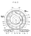
- FIG. 2 is a sectional view taken along the line VII-VII of FIG. 1;
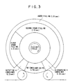
- FIG. 3 is a fill timing chart in the rotary type filling apparatus shown in FIG. 1;
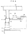
- FIG. 4 is a sectional view showing an enlarged part of FIG. 1;
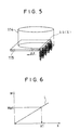
- FIG. 5 is a perspective view showing schematically a filling hopper and a shutter shown in FIG. 4;
- FIG. 6 is a graph showing a relationship between the weight of bulk material for use at the first stage filling and the opening degree of the shutter;
- FIG. 7 is a flow chart of filling control for bulk material;
- FIGS. 8(a) and 8(b) are graphs showing a relationship between the filling weight of bulk material and time;
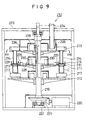
- FIG. 9 is a schematic view showing another example of a filling apparatus not falling within the scope of the appended claims;
- FIG. 10 is a sectional view taken along the line XVI-XVI of FIG. 9;
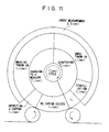
- FIG. 11 is a fill timing chart of the filling apparatus;
- FIG. 12 is an enlarged view of the major section of FIG. 9;
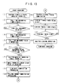
- FIG. 13 is a flow chart of filling control;
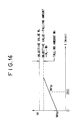
- FIG. 14 is a linear diagram showing a filling time curve;
- FIG. 15 is a linear diagram showing the major section of FIG. 14 in detail; and
- FIG. 16 is a linear diagram showing a flow rate calculation method.
-
- In a rotary type filling apparatus 110 as shown in FIG. 1, a plurality of the containers C as an object to be filled are installed on a disc (second base 112). While this disc is rotated, bulk material such as powder is gradually filled into respective containers C. This rotary type filling apparatus 110 comprises a turn table 113 acting as a storage portion, filling hoppers 114, first base 111, second base 112, shutters 115 acting as an opening/closing device, an encoder 116 for detecting a travel distance of load cells 117 for detecting weights, and a control unit 118.
- The turn table 113, the first base 111 and the second base 112 are fixed to a rotating shaft 119. The rotating shaft 119 is communicated with a driving motor 120 through a first bevel gear 121 and a second bevel gear 122 which mesh with each other. Thus, the turn table 113, the first base 111 and the second base 112 are rotated synchronously by means of the driving motor 120. The turn table 113, the first base 111, the second base 112, the rotating shaft 119, the driving motor 120 and the like are constructed so as to be surrounded by a casing 123.
- The turn table 113 is capable of storing powder and has a plurality of the filling hoppers 114 disposed along the circumference thereof. The casing 123 has a powder supplying cylinder 124, from which powder is supplied into the turn table 113 and stored thereon. A plate 125 for suppressing flying of bulk material is provided under the powder supplying cylinder 124 to suppress flying of bulk material when supplying.
- As the turn table 113 rotates, powder supplied from the powder supplying cylinder 124 thereto and stored thereon is forced outward in the diameter direction of the turn table 113 by the action of a force-out guiding plate 126 as shown in FIG. 2 and filled into the filling hoppers 114. Further, the action of a scratching plate 127 prevents a supply thereof to the filling hoppers 114.
- While powder is supplied to the filling hoppers 114 by the force-out guiding plate 126, filling of bulk material at the first stage which will be described later is conducted. While forcing powder outward by the force-out guiding plate 126 is conducted and then it is scratched by the scratching plate 127, filling thereof at the second stage which will be described later is conducted.
- As shown in FIG. 1, a plurality of the filling hoppers 114 are disposed such that the outlet openings thereof can be opened and closed individually by a plurality of the shutters 115. As shown in FIG. 4, shutter activating devices 128 for activating the shutters 115 are disposed on the first base 111. The shutter activating device 128 comprises an electric cylinder 129 driven by a servo motor and a motor driver 130. The motor driver 130 is activated by a command from the control unit 118 to drive the electric cylinder 129 thereby determining the opening degree of the shutter 115. By changing an opening degree determined by the shutter activating device 128, the shutter 115 is capable of continuously adjusting the supply amount (filling weight) of powder to be filled into the container C from the filling hopper 114. The electric-driven cylinder 129 is equipped with the encoder 116 for detecting a travel distance X for the opening/closing operation of the shutter 115 and this detected value X is output to a control unit 118.
- The second base 112 has a plurality of the load cells 117 disposed at respective positions corresponding to each of the filling hoppers 114 and the shutters 115. The containers C are placed on the load cells 117. The filling weight W of powder to be filled into the container C is detected by the load cell 117 and such a detected value W is output to the control unit 118.
- Meanwhile, the first base 111 has powder flying preventive plates 131 which surround the outlet of each of the filling hoppers 114 and each of the shutters 115 so as to prevent powder from flying and scattering when powder is thrown into the container C from the filling hopper 114 thereby enhancing scaling performance between the filling hopper 114 and the container C.
- As shown in FIG. 2, the container C is mounted on a transportation conveyor 132 and transported thereby and the transportation pitch of the container C is adjusted by a pitch adjusting device 133. Then the container C is carried onto the load cell 117 of the second base 112 by means of a supplying side star wheel 134. After the container C is filled with powder, it is sent out from the load cell 117 of the second base 112 to the transportation conveyor 132 by means of the disfilling side star wheel 135.
- The control unit 118 controls the opening/closing operation of a shutter 115 through a shutter operating mechanism 128, determines the degree of the opening of the shutter 115 at real time and fills powder to a container C from a filling hopper 114. A travel distance X of the shutter 115 at an arbitrary time is input to the control unit 118 from the encoder 116 and further a powder filling weight W to the container C at an arbitrary time is input thereto from the load cell 117. This control unit 118 contains an objective filling amount Wp of powder to be filled into a single container, a predetermined ratio α of the first stage objective filling amount Wp1 (described later) relative to this Wp, a linear approximation data L as shown in FIG. 6 indicating a relationship between the travel distance X of the shutter 115 and the filling weight W of powder to be filled into the container C, and an inverse function F(S) determined by the shape of the outlet shape of the filling hopper 114. This inverse function F(S) is fixed as follows, because as shown in FIG. 5, the change rate ΔS of the outlet opening area S of the filling hopper 114 in the interval of a minute time is determined as a function of the change rate ΔX of the travel distance X of the shutter 115 in this while:
- Here, a measuring method for the fluidity Uρ of powder will be described. In FIG. 5, assuming that the change rate of the travel distance of the shutter 115 in the interval of a minute time Δt is ΔX, the change rate of the outlet opening area of the filling hopper 114 is ΔS, the drop velocity of powder is U, and the specific gravity of powder is ρ, the change rate ΔQ of the filling weight of powder to be filled by powder dropping to the container C in this minute interval of time Δt is determined as follows:
- The ΔQ can be obtained from the filling weight W of powder measured by the load cell 117, the ΔS(X) can be obtained from the travel distance X of the shutter 115 measured by the encoder 116 and the Δt has been preliminarily determined as a sampling interval. Thus, the fluidity U ρ of powder in this minute interval of time Δt can be measured according to the following expression (3).
- The fluidity Uρ of powder varies depending on the size of the particles of bulk material, percentage of voids of the powder particles, the shape of the powder particles, specific gravity of the powder, temperature and humidity in the filling hopper 114, the powder flying preventive plate 131 and the container C, and friction of the walls of the filling hopper 114, the powder flying preventive plate 131, and the container C, and the flow condition of air in the filling hopper 114, the powder flying preventive plate 131 and the container C and the like. This fluidity U ρ of powder affects the accuracy in weight of powder to be filled when the powder is thrown into the container C from the filling hopper 114.
- Meanwhile, the control unit 118 executes filling of the first and second stages when filling of powder from the filling hopper 114 into the container C is started (step (1) in FIG. 7).
- At the first stage filling, the control unit 118 calculates a first stage objective filling weight Wp1 from an objective filling weight Wp and the predetermined ratio α according to the expression (5) below (step (2)).
- At the first stage filling, when the measured value of the filling weight W in the container C which is to be measured by the load cell 117 exceeds the first stage objective filling weight Wp1, the control unit 118 closes the shutter 115 from the specified opening degree X1 so as to change over from the first stage filling to the second stage filling (step (6), (7)). This change-over time is first stage filling completion time and further second stage filling start up time. This change-over time is assumed to be t1.
- Because the measured value W(t1) by the load cell 117 at this change-over time t1 is W(t1), the control unit 118 calculates the second stage objective filling weight Wp2 according to the expression below (6) (step (8)).
- X (t2) = initial travel distance a (a = 1mm)
- V (t2) = a/Δt
-
- Meanwhile, the reason why the measured value of the load cell 117 drops at time t1 as shown in FIGs. 8(a) and 8(b) is due to an influence of the acceleration applied to powder at the first stage filling and that the measured value of the load cell 117 indicates a higher value than an actual filling weight.
- At the time t2 of the second stage filling, based on the travel distances X(t1), X(t2) of the shutter 115 at the respective times t1, t2 measured by the encoder 116, the control unit 118 calculates a change rate of the outlet opening area of the filling hopper 114 in this while as follows:
- At time t2, the control unit 118 calculates the closing travel distance X(t3) and travel speed V(t3) of the shutter 115 to be moved in an interval of minute time Δt up to next time t3, based on the fluidity U ρ (t2) according to the expression (4) as follows:
- Likewise, at the second stage filling time t3, the control unit 118 calculates a change rate of the outlet opening area of the filling hopper 114 in an interval of minute time Δt from time t2 to time t3, according to;
Based on the fluidity Uρ (tn) of this bulk material 2, the control unit 118 calculates the closing travel distance X(tn+1) and travel speed V(tn+1) of the shutter 115 to be moved in an interval of minute time Δt from time tn to next time tn+1 using the expression (4) according to the following expression; - The control unit 118 repeats the above described second stage filling operation until the filling weight applied from the second stage filling start up time t1 to an arbitrary time tn coincides with Wp2, that is, until as shown in FIG. 8(b), the filling weight applied up to an arbitrary time tn coincides with an objective filling weight Wp, in other words, until Wp2 - (W(t2) - W(t1)) = Wp - W(tn) → 0 (step (11)). If the above coincidence is attained, the shutter 115 is made to close fully such that the filling of powder is terminated (step (12)).
- In the rotary type filling apparatus 110 having the construction described above, for example as shown in FIG. 3, the turn table 113 and the first base 111 and the second base 112 make a single turn in 4 seconds and the weight of the container C carried to the load cell 117 of the second base 112 from the supplying side star wheel 134 is detected by the load cell 117 in the first 0.2 seconds. In the next 0.1 seconds, filling at the first stage from the filling hopper 114 to the container C is conducted such that rapid filling at a massive filling rate is achieved. In the next 0.2 seconds, filling at the second stage from the filling hopper 114 to the container C is conducted such that a high precision filling at a minute filling rate is achieved. Then, the container C in which powder is fully filled is carried out to the transportation conveyor 132 by means of the disfilling side star wheel 135 in 0.24 seconds and in the next 0.56 seconds, no container C is placed on the load cell 117.
- According to the above described embodiment, because the shutter 115 is opened up to a specified opening degree X1 at the first stage filling such that the powder can be massively filled into the container C up to its first stage objective filling weight Wp1, the powder can be filled rapidly.
- Further, at the second stage filling, the shutter 115 is activated so as to be closed from its specified opening degree X1. According to the change rate ΔS of the outlet opening area of the filling hopper 114 and the change rate ΔQ of the filling weight W of powder, based on the closing travel distance X of the shutter 115 in an interval of a certain minute time Δt, the fluidity Uρ of bulk material in the interval of that minute time Δt is calculated at real time. Then, based on this fluidity Uρ , the closing travel distance X and the closing travel speed V of the shutter 115 in a next interval of minute time Δt are calculated and the shutter 115 is closed such that the filling is completed. As described above, because the fluidity Uρ of powder is calculated and measured at real time while it is being filled and based on this fluidity Uρ, the opening degree of the shutter 115 is controlled so as to determine the full closing timing of the shutter 115. Thus, it is possible to reduce the amount of powder existing between the shutter 115 and the container C to a minimum extent particularly when the shutter 115 is operated so as to be closed fully, so that a high precision filling can be achieved.
- Although a case of powder is described as bulk material in the above described embodiment, the same operation can be attained in a case of grain. Further, although a case of the rotary type filling apparatus is described in this embodiment, it is possible to apply the present invention to the other filling apparatus.
- In a rotary type filling apparatus 210 as shown in FIG. 9, which is not claimed, a plurality of the containers C as an object to be filled are installed on a disc (second base 212). While this disc is rotated, bulk material such as powder is gradually filled into respective containers C. This rotary type filling apparatus 210 comprises a turn table 213 acting as a storage portion, filling hoppers 214, a first base 211, the second base 212, shutters 215 acting as an opening/closing device, load cells 217 for detecting weights, and a control unit 218.
- The turn table 213, the first base 211 and the second base 212 are fixed to a rotating shaft 219. This rotating shaft 219 is communicated with a driving motor 220 through a first bevel gear 221 and a second bevel gear 222 which mesh with each other. Thus, the turn table 213, the first base 211 and the second base 212 are rotated synchronously by means of the driving motor 220. The turn table 213, the first base 211, the second base 212, the rotating shaft 219, the driving motor 220 and the like are constructed so as to be surrounded by a casing 223.
- The turn table 213 is capable of storing powder and has a plurality of the filling hoppers 214 disposed along the circumference thereof. The casing 223 has a powder supplying cylinder 224, from which powder is supplied into the turn table 213 and stored thereon.
- As the turn table 213 rotates, powder supplied from the powder supplying cylinder 224 thereto and stored thereon is forced outward in the diameter direction of the turn table 213 by the action of a force-out guiding plate 226 as shown in FIG. 10 and filled into the filling hoppers 214. Further, the action of a scratching plate 227 prevents a supply thereof to the filling hoppers 214.
- While powder is supplied to the filling hoppers 214 by the force-out guiding plate 226, filling of bulk material at the massive throw-in stage which will be described later is conducted. While forcing powder outward by the force-out guiding plate 226 is conducted and then it is scratched by the scratching plate 227, filling thereof at the small throw-in stage which will be described later is conducted.
- As shown in FIG. 9, a plurality of the filling hoppers 214 are disposed such that the outlet openings thereof can be opened and closed individually by a plurality of the shutters 215. As shown in FIG. 12, shutter activating devices 228 for activating the shutters 215 are disposed on the first base 211. This shutter activating device 228 comprises an electric cylinder 229 driven by a servo motor and a motor driver 230. This motor driver 230 is activated by a command from the control unit 218 to drive the electric cylinder 229 thereby determining the opening degree of the shutter 215. By changing an opening degree determined by the shutter activating device 228, this shutter 215 is capable of adjusting continuously the supply amount (filling weight) of powder to be filled into the container C from the filling hopper 214. That is, the control unit 218 controls so as to supply a specified initial filling amount of powder massively with the shutter 215 opened at a massive opening degree at the massive throw-in stage, and then supply a remaining filling amount thereof at a small flow rate at the small throw-in stage thereby completing a filling of an objective filling weight (W0) of powder in the container C.
- The second base 212 has a plurality of the load cells 217 disposed at respective positions corresponding to each of the filling hoppers 214 and the shutters 215. The containers C are placed on the load cells 217. The filling weight W of powder to be filled into the container C is detected by the load cell 217 and such a detected value W is output to the control unit 218.
- Meanwhile, the first base 211 has powder flying preventive plates 231 which surround the outlet of each of the filling hoppers 214 and each of the shutters 215 so as to prevent powder from flying and scattering when powder is thrown into the container C from the filling hopper 214 thereby enhancing the sealing performance between the filling hopper 214 and the container C.
- As shown in FIG. 10, the container C is mounted on a transportation conveyor 232 and transported thereby and the transportation pitch of the container C is adjusted by a pitch adjusting device 233. Then the container C is carried onto the load cell 217 of the second base 212 by means of a supplying side star wheel 234. After the container C is filled with powder, it is sent out from the load cell 217 of the second base 212 to the transportation conveyor 232 by means of the disfilling side star wheel 235.
- The filling amount control operation by the control unit 218 is conducted as follow (see FIG. 13).
- (A) Massive throw-in stage (FIG. 14)
The initial filling weight at the massive throw-in stage is assumed
to be α (e.g. 98%) relative to the objective filling weight (W0).
- (1) The shutter 215 is opened by the shutter activating device 228. Then, the shutter 215 is kept at a specified large opening degree (step (1)).
- (2) A fall time measuring timer is started at a shutter 215 opening start timing (step (2)). When the load cell 217 detects a weight of powder (step (3)), the fall time measuring timer is stopped and a fall time (tτ) of powder which falls from the outlet opening of the filling hopper 214 into the container C is output (step (4)). This fall time (tτ) is memorized in a memory (step (5)). Meanwhile, the control unit 218 utilizes the average value of the fall times measured at a filling operation of just nearby N cycle and memorized in the memory as the fall time described above for use in calculation of a falling amount which will be described later.
- (3) If such a detected value by the load cell 217 reaches the initial filling weight (W0 x α) at the massive throw-in stage, the opening degree of the shutter 215 is adjusted to a specified small opening degree by the shutter activating device 228. (steps (6), (7)) The reason why after the opening degree of the shutter 215 is changed to its small opening degree, the value detected by the load cell 217 drops with respect to its peak value as shown in FIG. 14 is that the fall acceleration of powder is applied to the load cell 217 when it strikes the load cell 217 such that the value measured by the load cell 217 exceeds the actual weight of powder already filled in the container C.
- (B) Small throw-in stage (FIGs. 14, 15)
- (1) After the opening degree of the shutter 215 is changed to its
small opening degree, the detected values W(Tn+1), W(Tn) of the load cell 217 at
the filling times Tn+1, Tn indicate a following relationship due to the action of the
application of the fall acceleration of the powder described above,
- (2) A flow rate q of powder made to flow from the filling hopper
214 is measured (step (9)). Based on Wsp, a detected value Wtp of the load cell
217 when bmsec has passed is obtained. (FIG. 16) The flow rate q is determined
as follows.
- (3) The falling amount Wh existing in the air from just below the
outlet opening of the filling hopper 214 closed by the shutter 215 to the container
C is calculated from the previously mentioned fall time (tτ) and the flow rate (q)
according to;
- (4) The closing timing of the shutter 215 is calculated (step (11)).
The timing in which the filling weight W filled to the container C at the small
throw-in stage reaches
- (5) Based on the closing timing t calculated in (4) above, the closing timing timer value is set (step (12)). Then, the closing timing timer is started (step (13)) and when the measured value of the closing timing timer reaches its set value (step (14)), the shutter 15 is closed (step (15) and then the filling operation is completed.
-
- In the rotary type filling apparatus 210 having the construction described above, for example as shown in FIG. 11, the turn table 213 and the first base 11 and the second base 212 make a single turn in T seconds and the weight of the container C carried to the load cell 217 of the second base 212 from the supplying side star wheel 234 is detected by the load cell 217 in first t1 seconds. In the next t2 seconds, filling at the massive throw-in stage from the filling hopper 214 to the container C is conducted such that rapid filling at a massive filling rate is achieved. In the next t3 seconds, filling at the small throw-in stage from the filling hopper 214 to the container C is conducted such that a high precision filling at a minute filling rate is achieved. After a stable interval of t4 (allowance time), the container C in which powder is fully filled is carried out to the transportation conveyor 232 by means of the disfilling side star wheel 235 in t5 seconds and in the next t6 seconds, no container C is placed on the load cell 217.
- Thus, the following operations (1)-(3) are attained according to the present embodiment.
- (1) Because the shutter 215 is opened at a specified opening degree at the massive filling stage and powder can be massively filled to the container C up to the initial filling weight, rapid filling of powder can be done.
- (2) At the small filling stage, the amount of powder (falling amount Wh) existing in the air (falling height) from just below the outlet opening of the filling hopper 214 closed by the shutter 215 to the container C is calculated and the shutter 215 is closed at the timing in which the filling weight (W) of powder fully filled in the container C reaches W = W0 - Wh. While powder is being filled, the fall time tτ and flow rate q of powder are measured at real time and based on such a measured value, the closing timing of the shutter 215 is determined. Thus, a high precision filling can be achieved without being affected by a change of the characteristics of powder and a necessity of container C type change-over time.
- (3) By adopting the fall time t τ of powder for use in calculation of the falling amount Wh as an average of the fall time t τ measured in just nearby N cycle filling operation, the filling accuracy can be improved.
-
- Although a case of powder is described as bulk material in the above described embodiment, the same operation can be attained in a case of grain. Further, although a case of the rotary type filling apparatus is described in this embodiment, it is possible to apply the present invention to other filling apparatuses.
Claims (2)
- A method for filling bulk material, in which an objective filling weight for filling bulk material stored in a storage portion (113) to a filling object is divided to a first stage objective filling weight and a second stage objective filling weight, the method comprising:a first stage filling step which comprises setting an opening/closing mechanism (115) provided on said storage portion (113) to a predetermined opening degree and filling the bulk material from said storage portion (113) to said filling object until said first stage objective filling weight is reached; and characterized bya second stage filling step which comprises activating said opening/closing mechanism (115) so as to close from said predetermined opening degree, detecting a closing travel distance of said opening/closing mechanism (115) in a certain minute time interval and a filling weight of bulk material, and based on said detected values, calculating a fluidity of the bulk material in such a minute time interval; anda step of calculating a closing travel distance and a closing travel speed of said opening/closing mechanism (115) in a next minute time interval based on the fluidity so as to activate said opening/closing mechanism (115) to close thereby filling the bulk material to said filling object,and wherein said second stage filling step and said calculating step are repeated until a difference of said objective filling weight and a weight measured at the beginning of said minute time interval is substantially equal to zero so as to entirely close said opening/closing mechanism (115).
- An apparatus for filling bulk material, the apparatus comprising:a storage portion (113) for storing bulk material;an opening/closing mechanism (115) disposed on said storage portion (113), for continuously adjusting a supply amount of the bulk material to be supplied from said storage portion to a filling object by an opening/closing action;a travel distance detecting device (116) for detecting an opening / closing travel distance of said opening/closing device (115);a weight detecting device (117) for detecting a filling weight of the bulk material to be filled into said filling object; anda control unit (118) for controlling an opening/closing operation of said opening/closing mechanism (115);said control unit (118) controlling according to a first stage filling in which the opening/closing mechanism (115) is set to a predetermined opening degree and the bulk material is filled from said storage portion (113) to said filling object until a first stage objective filling weight is reached; and characterized by said control unit (118) controlling according to a second stage filling in which said opening/closing mechanism is activated so as to close from said predetermined opening degree, and a fluidity of the bulk material in a certain minute time interval is calculated from a closing travel distance of said opening/close mechanism and a filling weight of the bulk material, which are detected by said travel distance detecting device and said weight detecting device in said certain minute time interval; anda closing travel distance and a closing travel speed of said opening/closing mechanism in a next minute time interval are calculated based on the fluidity so as to activate said opening/closing mechanism to close thereby filling the bulk material to said filling object, and to entirely close said opening/closing mechanism when a difference of said objective filling weight and a weight measured at the beginning of said next minute time interval is substantially equal to zero.
Applications Claiming Priority (7)
| Application Number | Priority Date | Filing Date | Title |
|---|---|---|---|
| JP34613295A JP2896109B2 (en) | 1995-12-12 | 1995-12-12 | Filling control method and filling control device for granular material |
| JP34613295 | 1995-12-12 | ||
| JP346132/95 | 1995-12-12 | ||
| JP196982/96 | 1996-07-09 | ||
| JP19698296 | 1996-07-09 | ||
| JP19698296A JP2863736B2 (en) | 1996-07-09 | 1996-07-09 | Method and apparatus for filling granular material |
| PCT/JP1996/003532 WO1997021590A1 (en) | 1995-12-12 | 1996-12-03 | Method and apparatus for filling bulk material |
Publications (2)
| Publication Number | Publication Date |
|---|---|
| EP0868346A1 EP0868346A1 (en) | 1998-10-07 |
| EP0868346B1 true EP0868346B1 (en) | 2001-03-14 |
Family
ID=26510093
Family Applications (1)
| Application Number | Title | Priority Date | Filing Date |
|---|---|---|---|
| EP96939348A Expired - Lifetime EP0868346B1 (en) | 1995-12-12 | 1996-12-03 | Method and apparatus for filling bulk material |
Country Status (6)
| Country | Link |
|---|---|
| US (1) | US6000444A (en) |
| EP (1) | EP0868346B1 (en) |
| CN (1) | CN1120114C (en) |
| DE (1) | DE69612111T2 (en) |
| ES (1) | ES2155947T3 (en) |
| WO (1) | WO1997021590A1 (en) |
Families Citing this family (11)
| Publication number | Priority date | Publication date | Assignee | Title |
|---|---|---|---|---|
| US6325113B1 (en) * | 2000-02-02 | 2001-12-04 | Masco Corporation Of Indiana | Dosing dispenser for powder material |
| GB0029362D0 (en) * | 2000-12-01 | 2001-01-17 | Pa Consulting Services | Particle dispense rate regulator |
| ITBO20030407A1 (en) * | 2003-07-01 | 2005-01-02 | Azionaria Costruzioni Acma Spa | FILLER CONTAINER MACHINE WITH A MATERIAL OF |
| US7451015B2 (en) * | 2003-10-23 | 2008-11-11 | Buy The Pound, Inc. | System and method for dispensing bulk products |
| DE102011101045A1 (en) * | 2011-05-09 | 2012-11-15 | Haver & Boecker Ohg | Packing machine and method for filling open bags |
| JP6111391B2 (en) * | 2013-05-01 | 2017-04-12 | ゼネラルパッカー株式会社 | Method for processing residual package in packaging machine and packaging machine |
| CN103482126A (en) * | 2013-08-29 | 2014-01-01 | 苏州国衡机电有限公司 | Net weight type open-pocket packing machine |
| EP2930139B1 (en) * | 2014-04-08 | 2017-02-01 | Sidel S.p.a. Con Socio Unico | A container filling machine provided with an improved weighing device and related weighing method |
| JP7022056B2 (en) * | 2016-03-31 | 2022-02-17 | 住友精化株式会社 | Granular material filling device and filling method |
| KR102539813B1 (en) | 2017-03-10 | 2023-06-02 | 가부시끼가이샤 사따께 | Flow measuring device and flow measuring method |
| EP4697007A1 (en) * | 2024-08-14 | 2026-02-18 | Fraunhofer-Gesellschaft zur Förderung der angewandten Forschung e.V. | Device and method for determining flow properties of a powder or bulk material in different flow regimes |
Family Cites Families (12)
| Publication number | Priority date | Publication date | Assignee | Title |
|---|---|---|---|---|
| US2829856A (en) * | 1956-06-19 | 1958-04-08 | Edwin C Gregory | Weighing and feeding control system |
| DE2013687A1 (en) * | 1970-03-21 | 1971-12-23 | Gulde-Regelarmaturen KG, 6700 Ludwigshafen-Oggersheim | Bagging scales |
| DE2028506A1 (en) * | 1970-06-10 | 1971-12-16 | Zellstoffabrik Waldhof, 6800 Mannheim-Waldhof | Machine for filling and weighing bags at the same time |
| JPS54113362A (en) * | 1978-02-24 | 1979-09-04 | Yousuke Miyata | Machine for automatically measuring fixed quantity of powder |
| EP0032481A3 (en) * | 1980-01-11 | 1982-12-08 | Firma M. Jeger | Device for controlling the quantity of fluent solid material |
| DE3106473A1 (en) * | 1981-02-21 | 1982-09-09 | Haver & Boecker, 4740 Oelde | "METHOD FOR AUTOMATICALLY ADJUSTING THE DISCONNECTING POINT OF THE FILLING FLOW OF AN ELECTROMECHANICAL SCALE" |
| DE3127131C2 (en) * | 1981-07-09 | 1983-09-29 | Behn Maschinenfabrik GmbH & Co KG, 4150 Krefeld | Process and device for the gravimetric filling of containers and sacks in coarse and fine flow |
| JPS5852001A (en) * | 1981-09-08 | 1983-03-28 | 味の素株式会社 | Filler for fixed quantity of powdered and granular body |
| US4621664A (en) * | 1984-10-03 | 1986-11-11 | Diffracto Ltd. | Filling machines |
| EP0406092B1 (en) * | 1989-06-27 | 1993-01-13 | Group S.E.R.A.C. | Device for filling containers with weighted measures |
| JP2984059B2 (en) * | 1991-01-29 | 1999-11-29 | ビューラー・アクチェンゲゼルシャフト・マシイネンファブリーク | Method and apparatus for bagging bulk material with a predetermined filling volume |
| FR2679516B1 (en) * | 1991-07-23 | 1993-11-12 | Andre Graffin | WEIGHT DOSING METHOD AND DEVICE FOR FILLING CONTAINERS. |
-
1996
- 1996-12-03 ES ES96939348T patent/ES2155947T3/en not_active Expired - Lifetime
- 1996-12-03 WO PCT/JP1996/003532 patent/WO1997021590A1/en not_active Ceased
- 1996-12-03 DE DE69612111T patent/DE69612111T2/en not_active Expired - Fee Related
- 1996-12-03 EP EP96939348A patent/EP0868346B1/en not_active Expired - Lifetime
- 1996-12-03 CN CN96198994A patent/CN1120114C/en not_active Expired - Fee Related
- 1996-12-03 US US09/077,883 patent/US6000444A/en not_active Expired - Fee Related
Also Published As
| Publication number | Publication date |
|---|---|
| CN1204289A (en) | 1999-01-06 |
| DE69612111D1 (en) | 2001-04-19 |
| WO1997021590A1 (en) | 1997-06-19 |
| ES2155947T3 (en) | 2001-06-01 |
| DE69612111T2 (en) | 2001-08-02 |
| EP0868346A1 (en) | 1998-10-07 |
| US6000444A (en) | 1999-12-14 |
| CN1120114C (en) | 2003-09-03 |
Similar Documents
| Publication | Publication Date | Title |
|---|---|---|
| US4856563A (en) | Method and apparatus for filling liquid into containers | |
| EP3363625A1 (en) | Powdery material feeding device and powdery material feeding method | |
| US6000444A (en) | Method and apparatus for filling bulk material | |
| US20110203701A1 (en) | Method and apparatus for the filling of target containers | |
| US7117653B2 (en) | Flavoring system and method | |
| EP1347870A1 (en) | A system for feeding portions of material to an injection molding machine | |
| AU2002217403A1 (en) | A system for feeding portions of material to an injection molding machine | |
| US8768632B2 (en) | Method and apparatus for the filling of target containers | |
| EP0488318B1 (en) | Control method of and apparatus for material charging at top of blast furnace | |
| JP2002096802A (en) | Weighing-type fully automatic powder dividing method, weighing-type fully automatic powder dividing device and weighing-type fully automatic powder dividing and packaging device | |
| KR20040045397A (en) | Mixing System and Method | |
| JPS61266512A (en) | Method for controlling charging to shaft furnace | |
| JPS593222A (en) | Method and device for measuring weight of fluidized solid bulk material | |
| JP2863736B2 (en) | Method and apparatus for filling granular material | |
| JP2009029517A (en) | Heavy-weight filling device | |
| CN117645170B (en) | An adaptive loading method for a rotary three-compartment quantitative loading station | |
| JP2896109B2 (en) | Filling control method and filling control device for granular material | |
| JPS59145715A (en) | Control method of raw material control gate | |
| JP3616793B2 (en) | How to measure the weight of powder | |
| JP2553552B2 (en) | Continuous powder measuring device | |
| JP2699100B2 (en) | Quantitative filling method | |
| JPS63279120A (en) | Supply amount control apparatus of weighing machine | |
| JPS6191520A (en) | Weighing/filling control method and apparatus | |
| JPH08192802A (en) | Method and device for filling powder container with container | |
| EP3922448B1 (en) | Powdery material mixing degree measurement device and compression molding system |
Legal Events
| Date | Code | Title | Description |
|---|---|---|---|
| PUAI | Public reference made under article 153(3) epc to a published international application that has entered the european phase |
Free format text: ORIGINAL CODE: 0009012 |
|
| 17P | Request for examination filed |
Effective date: 19980610 |
|
| AK | Designated contracting states |
Kind code of ref document: A1 Designated state(s): DE ES FR GB |
|
| 17Q | First examination report despatched |
Effective date: 19981209 |
|
| GRAG | Despatch of communication of intention to grant |
Free format text: ORIGINAL CODE: EPIDOS AGRA |
|
| GRAG | Despatch of communication of intention to grant |
Free format text: ORIGINAL CODE: EPIDOS AGRA |
|
| GRAG | Despatch of communication of intention to grant |
Free format text: ORIGINAL CODE: EPIDOS AGRA |
|
| GRAH | Despatch of communication of intention to grant a patent |
Free format text: ORIGINAL CODE: EPIDOS IGRA |
|
| GRAH | Despatch of communication of intention to grant a patent |
Free format text: ORIGINAL CODE: EPIDOS IGRA |
|
| GRAA | (expected) grant |
Free format text: ORIGINAL CODE: 0009210 |
|
| AK | Designated contracting states |
Kind code of ref document: B1 Designated state(s): DE ES FR GB |
|
| REF | Corresponds to: |
Ref document number: 69612111 Country of ref document: DE Date of ref document: 20010419 |
|
| ET | Fr: translation filed | ||
| REG | Reference to a national code |
Ref country code: ES Ref legal event code: FG2A Ref document number: 2155947 Country of ref document: ES Kind code of ref document: T3 |
|
| REG | Reference to a national code |
Ref country code: GB Ref legal event code: IF02 |
|
| PLBE | No opposition filed within time limit |
Free format text: ORIGINAL CODE: 0009261 |
|
| STAA | Information on the status of an ep patent application or granted ep patent |
Free format text: STATUS: NO OPPOSITION FILED WITHIN TIME LIMIT |
|
| 26N | No opposition filed | ||
| PGFP | Annual fee paid to national office [announced via postgrant information from national office to epo] |
Ref country code: GB Payment date: 20061129 Year of fee payment: 11 |
|
| PGFP | Annual fee paid to national office [announced via postgrant information from national office to epo] |
Ref country code: DE Payment date: 20061130 Year of fee payment: 11 |
|
| PGFP | Annual fee paid to national office [announced via postgrant information from national office to epo] |
Ref country code: FR Payment date: 20061208 Year of fee payment: 11 |
|
| PGFP | Annual fee paid to national office [announced via postgrant information from national office to epo] |
Ref country code: ES Payment date: 20061228 Year of fee payment: 11 |
|
| GBPC | Gb: european patent ceased through non-payment of renewal fee |
Effective date: 20071203 |
|
| PG25 | Lapsed in a contracting state [announced via postgrant information from national office to epo] |
Ref country code: DE Free format text: LAPSE BECAUSE OF NON-PAYMENT OF DUE FEES Effective date: 20080701 |
|
| REG | Reference to a national code |
Ref country code: FR Ref legal event code: ST Effective date: 20081020 |
|
| PG25 | Lapsed in a contracting state [announced via postgrant information from national office to epo] |
Ref country code: GB Free format text: LAPSE BECAUSE OF NON-PAYMENT OF DUE FEES Effective date: 20071203 |
|
| REG | Reference to a national code |
Ref country code: ES Ref legal event code: FD2A Effective date: 20071204 |
|
| PG25 | Lapsed in a contracting state [announced via postgrant information from national office to epo] |
Ref country code: FR Free format text: LAPSE BECAUSE OF NON-PAYMENT OF DUE FEES Effective date: 20071231 Ref country code: ES Free format text: LAPSE BECAUSE OF NON-PAYMENT OF DUE FEES Effective date: 20071204 |