EP0867296B1 - Ink jet recording apparatus - Google Patents
Ink jet recording apparatus Download PDFInfo
- Publication number
- EP0867296B1 EP0867296B1 EP98105419A EP98105419A EP0867296B1 EP 0867296 B1 EP0867296 B1 EP 0867296B1 EP 98105419 A EP98105419 A EP 98105419A EP 98105419 A EP98105419 A EP 98105419A EP 0867296 B1 EP0867296 B1 EP 0867296B1
- Authority
- EP
- European Patent Office
- Prior art keywords
- ink
- recording
- recording head
- nozzle plate
- ink jet
- Prior art date
- Legal status (The legal status is an assumption and is not a legal conclusion. Google has not performed a legal analysis and makes no representation as to the accuracy of the status listed.)
- Expired - Lifetime
Links
Images


Classifications
-
- B—PERFORMING OPERATIONS; TRANSPORTING
- B41—PRINTING; LINING MACHINES; TYPEWRITERS; STAMPS
- B41J—TYPEWRITERS; SELECTIVE PRINTING MECHANISMS, i.e. MECHANISMS PRINTING OTHERWISE THAN FROM A FORME; CORRECTION OF TYPOGRAPHICAL ERRORS
- B41J2/00—Typewriters or selective printing mechanisms characterised by the printing or marking process for which they are designed
- B41J2/005—Typewriters or selective printing mechanisms characterised by the printing or marking process for which they are designed characterised by bringing liquid or particles selectively into contact with a printing material
- B41J2/01—Ink jet
- B41J2/135—Nozzles
- B41J2/165—Preventing or detecting of nozzle clogging, e.g. cleaning, capping or moistening for nozzles
- B41J2/16517—Cleaning of print head nozzles
- B41J2/16535—Cleaning of print head nozzles using wiping constructions
- B41J2/16538—Cleaning of print head nozzles using wiping constructions with brushes or wiper blades perpendicular to the nozzle plate
-
- B—PERFORMING OPERATIONS; TRANSPORTING
- B41—PRINTING; LINING MACHINES; TYPEWRITERS; STAMPS
- B41J—TYPEWRITERS; SELECTIVE PRINTING MECHANISMS, i.e. MECHANISMS PRINTING OTHERWISE THAN FROM A FORME; CORRECTION OF TYPOGRAPHICAL ERRORS
- B41J2/00—Typewriters or selective printing mechanisms characterised by the printing or marking process for which they are designed
- B41J2/005—Typewriters or selective printing mechanisms characterised by the printing or marking process for which they are designed characterised by bringing liquid or particles selectively into contact with a printing material
- B41J2/01—Ink jet
- B41J2/135—Nozzles
- B41J2/165—Preventing or detecting of nozzle clogging, e.g. cleaning, capping or moistening for nozzles
- B41J2/16517—Cleaning of print head nozzles
- B41J2/16535—Cleaning of print head nozzles using wiping constructions
- B41J2/16541—Means to remove deposits from wipers or scrapers
Definitions
- the present invention relates to a recording apparatus provided with a recording head for expelling ink droplets and particularly to a cleaning device for a recording head.
- European patent application EP 0 449 324 Al discloses an ink jet recording apparatus comprising a recording head mounted on a carriage, a cleaning blade and an ink absorbing material provided in the vicinity of the recording head, within reach of the cleaning blade.
- an ink jet color printer has an extremely small size and is capable of color printing if inks having different colors are used. Accordingly, an ink jet color printer has been put into practical use which includes a carriage provided with a black recording head for expelling a black ink and a color recording head for expelling yellow, cyan and magenta inks to enable text printing with a black ink as well as full-color printing.
- Such an ink jet recording head is disadvantageous in that since an ink pressed in a pressure-producing chamber is jetted onto a recording paper in the form of ink droplet from a nozzle opening, the ink exhibits a raised viscosity or solidifies due to the evaporation of ink solvent or attracts dust or paper dust to cause malprinting.
- an ink jet recording apparatus normally includes a capping means for sealing the nozzle opening in the recording head while printing is not effected to prevent ink drying as well as a cleaning means which comes in sliding contact with the nozzle plate to give physical resolution to clogging in the nozzle opening.
- Such a cleaning means is in the form of a blade formed by a plate made of an elastic material such as rubber.
- the cleaning mechanism is arranged such that when the carriage moves the recording head back and forth with the cleaning means protruding to a position at which it can come in elastic contact with the nozzle plate of the recording head, the tip of the blade can scratch dust and ink dregs off the nozzle plate with the ink.
- the cleaning blade Since the cleaning blade is brought into contact with the side of the recording head shortly before it comes in elastic contact with the nozzle plate of the recording head so that the ink containing paper dust or solid content is wiped off the cleaning blade, it can stay clean itself when applied to cleaning operation for the nozzle plate of the recording head.
- this cleaning mechanism is disadvantageous in that when the cleaning blade leaves the recording head shortly after the termination of the cleaning operation to release the elastic force, it springs back to cause the ink wiped to fly in the form of droplets that stain the adjacent recording head and the interior of the housing.
- a cleaning mechanism comprising another cleaning member provided in a non-printing zone for scratching ink, dust and ink dregs off the cleaning blade whereby the carriage is allowed to move to the cleaning member prior to the beginning of cleaning operation where the ink is scratched off the cleaning blade, and then allowed to move back to the original position where cleaning operation then begins.
- this cleaning mechanism is disadvantageous in that since the carriage needs to perform an extra movement to remove the ink from the cleaning blade, it adds to the entire cleaning time.
- the present invention provides an ink jet recording apparatus as specified in claims 1 and 2.
- the present invention concerns an ink jet recording apparatus comprising a recording head which jets ink droplets from an opening in a nozzle plate in response to printing signal, a carriage having said recording head mounted thereon which performs scanning movement relative to a recording medium and a cleaning blade which comes in elastic contact with said nozzle plate, provided in that said cleaning blade has been subjected to ink-receptive treatment on at least the surface thereof which comes in contact with said nozzle plate.
- the ink can be retained on the cleaning blade regardless of the rebound of the cleaning blade.
- the ink wiped off the nozzle plate can be prevented from flying from the cleaning blade, inhibiting stain on the housing or the adjacent recording head.
- the present invention concerns an ink jet printing apparatus comprising a recording head which jets ink droplets from an opening in a nozzle plate in response to printing signal, a carriage having said recording head mounted thereon which performs scanning movement relative to a recording medium and a cleaning blade which comes in elastic contact with said nozzle plate, characterized in that a wall portion are formed opposed to said recording head along the direction of scanning movement of said recording head in the vicinity of said recording head with a predetermined gap therefrom on the cleaning initiation side of said recording head and an ink-absorbing material is provided in a zone opposed to the tip of said wall portions during the capping of said recording head with said capping means.
- the ink can be scratched off the cleaning blade by the wall portion while the recording head is being cleaned. Accordingly, the nozzle plate can be cleaned in a short period of time without having restained and without necessity for extra movement of carriage.
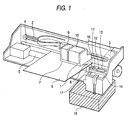
- Fig. 1 illustrates an embodiment of the ink jet recording apparatus according to the present invention.
- a carriage 1 is connected to a motor 3 via a timing belt 2 and is arranged to be able to move back and forth in the direction along the axis of a platen under the guidance of a guide member 4.
- the carriage 1 includes a recording head 7 for expelling black ink droplets and a recording head 8 for expelling color ink droplets mounted on the side thereof opposed to a recording paper 6 and ink cartridges 9 and 10 for supplying inks into the recording head 7 and the recording head 8, respectively, mounted removably on the upper surface thereof.
- a capping device 13 comprising cap members 11, 12 for sealing the nozzle opening in the recording heads 7, 8 which serves not only as a capping means for preventing the drying of the nozzle opening during the suspension of printing operation but also as an ink receiver during flushing operation and a suction means of acting negative pressure from a suction pump unit 14 on the recording heads 7, 8 to force the ink to be discharged therefrom.
- a waste ink absorption pad 15 made of a porous material having excellent ink receptivity and retention such as felt housed in a container not shown.
- a contact piece 18 Provided integrally with or separately of the waste ink absorption pad 15 is a contact piece 18 (see Fig. 2) which comes in contact with the side wall or bottom surface of a supporting member 17 supporting the blade 16 when a cleaning blade 16 described later is on standby.
- the cleaning blade 16 is provided in the vicinity of the capping device 13 and in the non-printing zone. As shown in Fig. 2, during cleaning operation, the cleaning blade 16 is in a position such that the tip thereof would protrude somewhat beyond the lower surface of the nozzle plate of the recording heads 7, 8 towards the ink cartridge to press itself against the nozzle plate and undergo elastic deformation (shown by the broken line). While cleaning operation is not effected, the cleaning blade 16 is on standby in a position such that the tip thereof doesn't come in contact with the nozzle plate of the recording heads 7, 8 and the supporting member 17 comes in contact with the contact piece 18 of the ink absorption pad 16 (shown by the solid line). The supporting member 17 has been subjected to ink-receptive treatment stronger than the cleaning blade 16 but weaker than the ink absorption pad.
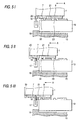
- Fig. 3 illustrates an embodiment of the foregoing blade 16.
- Formed on the surface of the blade 16 which comes in contact with the recording head are a plurality of grooves 19, 19, 19 ... having a width small enough to exhibit a capillary force that can retain an ink but great enough to perform cleaning without hindrance, extending from the tip towards the supporting member 17.
- the tip 20a, 21a of the wall portions 20, 21 are level with the nozzle plate of the recording heads 7, 8 or protrude beyond the nozzle plate of the recording heads 7, 8 somewhat ( ⁇ H) towards the recording paper (downward as viewed in the drawing).
- Fig. 4 (a) Formed in the wall portions 20, 21 on the surface thereof which comes in contact with the blade 16 are grooves or long holes 20b (21b) sealed by tips 20a, 21a as shown in Fig. 4 (a).
- the tips 20a, 21b of the wall portions 20, 21 is arranged such that the thickness d thereof is smaller than the indentation ⁇ L developed when they are elastically pressed against ink-absorbing materials 22, 23 described later as shown in Fig. 4 (b).
- ink-absorbing materials 22, 23 Provided on the capping device 13 are ink-absorbing materials 22, 23 with which at least the tips 20a, 21a of the wall portions 20, 21 come in contact during the capping of the recording heads 7, 8 in such an arrangement that the capping of the recording heads 7, 8 cannot be impeded.
- a cleaning switch is depressed to order cleaning.
- the blade 16 is then allowed to move such that the tip thereof protrudes beyond the nozzle plate of the recording heads 7, 8 towards the ink cartridge (upward as viewed in the drawing) and resides in a position suitable for cleaning.
- the ink wiped off the nozzle plate flies by inertia, it is shielded by the side wall 21 of the other recording head 8, preventing the stain on the recording head 8 with the ink.
- the blade 16 comes in contact with the wall portion 21 provided on the side of the recording head 8 so that the ink left on the blade 16 is scratched off by the wall portion 21 before cleaning of the nozzle plate of the recording head 8 in the same manner as for the recording head 7.
- the blade 15 is shunted to the original position.
- the carriage 1 then moves in the direction indicated by the arrow B in the drawing to the home position (see Fig. 6 (I)).
- the capping device 13 is moved towards the carriage 1 in linkage with the movement of the carriage 1 (upward as viewed in the drawing) to seal the recording heads 7, 8 with the capping members 11, 12.
- the tips 20a, 21a of the wall portions 20, 21 are elastically pressed against the ink-absorbing materials 22, 23 provided on the surface of the cleaning device 13.
- the periphery of the indentation point on the ink-absorbing materials 22, 23 is positioned closer to the fine holes 20b, 21b than to the tips 20a, 21a of the wall portion 20, 21 to come in contact with the fine holes 20b, 21b so that the ink retained in the fine holes 20b, 21b are absorbed by the ink-absorbing materials 22, 23.
- slender grooves 19 are formed extending vertically so that the ink can not only move towards the supporting member but also retain on the blade 16.
- an elastic plate material 24 such as rubber may be coated on the surface thereof which comes in contact with the nozzle plate with, as an ink-receptive treatment, a mixture of one or more selected from the group consisting of diethylene glycol, polyethylene glycol, polypropylene glycol, ethylene glycol, propylene glycol, butylene glycol, triethylene glycol, 1,2,6-hexanetriol, thioglycol, hexylene glycol, glycerin, trimethylolethane, trimethylolpropane, urea, 2-pyrrolidone, N-methyl-2-pyrrolidone and 1,3-dimethyl-2-imidazolidine, various surface active agents such as anionic surface active agent, cationic surface active agent and amphoteric surface active agent, and one or more
- a layer 26 which comes in contact with the nozzle plate may be formed by a porous material, and a backing material 27 such as rubber which gives an elasticity such that the blade 16 can come in elastic contact with the nozzle plate of the recording head may be laminated on the layer 26.
- the ink on the nozzle plate can be not only moved by the capillary force produced by the layer 26 made of a porous material towards the supporting member 17 of the blade 16 but also retained by the capillary force produced by the layer 26 made of a porous material strong enough to overcome the inertia force.
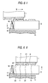
- the wall portions 16, 17 may have depressions 20d (21d) having openings 20c (21c) and a rectangular section formed therein at the end thereof on the surface thereof which comes in contact with the ink-absorbing material 18.
- the wall portions 16, 17 may have depressions 20f (21f) having openings 20e (21e) and a triangular section at the end thereof.
- the ink can be retained by the capillary force of the depressions 20d (21d) and 20f (21f).
- the wall portions 16, 17 come in contact with the ink-absorbing materials 22, 23, the ink can be easily moved from the tip openings 20c (21c) and 20e (21e) to the ink-absorbing materials 22, 23 by the action of the ink-absorbing materials 22, 23 having a stronger capillary force than the depressions 20d (21d) and 20f (21f).
Description
- The present invention relates to a recording apparatus provided with a recording head for expelling ink droplets and particularly to a cleaning device for a recording head.
- European patent application EP 0 449 324 Al discloses an ink jet recording apparatus comprising a recording head mounted on a carriage, a cleaning blade and an ink absorbing material provided in the vicinity of the recording head, within reach of the cleaning blade.
- The main body of an ink jet recording head has an extremely small size and is capable of color printing if inks having different colors are used. Accordingly, an ink jet color printer has been put into practical use which includes a carriage provided with a black recording head for expelling a black ink and a color recording head for expelling yellow, cyan and magenta inks to enable text printing with a black ink as well as full-color printing.
- Such an ink jet recording head is disadvantageous in that since an ink pressed in a pressure-producing chamber is jetted onto a recording paper in the form of ink droplet from a nozzle opening, the ink exhibits a raised viscosity or solidifies due to the evaporation of ink solvent or attracts dust or paper dust to cause malprinting.
- In order to overcome these disadvantages, an ink jet recording apparatus normally includes a capping means for sealing the nozzle opening in the recording head while printing is not effected to prevent ink drying as well as a cleaning means which comes in sliding contact with the nozzle plate to give physical resolution to clogging in the nozzle opening.
- Such a cleaning means is in the form of a blade formed by a plate made of an elastic material such as rubber. The cleaning mechanism is arranged such that when the carriage moves the recording head back and forth with the cleaning means protruding to a position at which it can come in elastic contact with the nozzle plate of the recording head, the tip of the blade can scratch dust and ink dregs off the nozzle plate with the ink.
- Since the cleaning blade is brought into contact with the side of the recording head shortly before it comes in elastic contact with the nozzle plate of the recording head so that the ink containing paper dust or solid content is wiped off the cleaning blade, it can stay clean itself when applied to cleaning operation for the nozzle plate of the recording head. However, this cleaning mechanism is disadvantageous in that when the cleaning blade leaves the recording head shortly after the termination of the cleaning operation to release the elastic force, it springs back to cause the ink wiped to fly in the form of droplets that stain the adjacent recording head and the interior of the housing.
- Another disadvantage is that the prolonged use of the recording head causes the ink to solidify and accumulate on the side thereof. The ink thus accumulated moves to the cleaning blade from which it then stains the recording head, impairing the effect of the cleaning blade of cleaning the nozzle plate. In order to overcome this difficulty, a cleaning mechanism is proposed comprising another cleaning member provided in a non-printing zone for scratching ink, dust and ink dregs off the cleaning blade whereby the carriage is allowed to move to the cleaning member prior to the beginning of cleaning operation where the ink is scratched off the cleaning blade, and then allowed to move back to the original position where cleaning operation then begins. However, this cleaning mechanism is disadvantageous in that since the carriage needs to perform an extra movement to remove the ink from the cleaning blade, it adds to the entire cleaning time.
- It is a first object of the present invention to provide an ink jet recording apparatus which is unliable to production of ink droplets due to the rebounding of the cleaning blade shortly after the termination of cleaning operation.
- To solve this object the present invention provides an ink jet recording apparatus as specified in
claims - E.g., the present invention concerns an ink jet recording apparatus comprising a recording head which jets ink droplets from an opening in a nozzle plate in response to printing signal, a carriage having said recording head mounted thereon which performs scanning movement relative to a recording medium and a cleaning blade which comes in elastic contact with said nozzle plate, provided in that said cleaning blade has been subjected to ink-receptive treatment on at least the surface thereof which comes in contact with said nozzle plate. In this arrangement, the ink can be retained on the cleaning blade regardless of the rebound of the cleaning blade.
- Accordingly, the ink wiped off the nozzle plate can be prevented from flying from the cleaning blade, inhibiting stain on the housing or the adjacent recording head.
- It is a second object of the present invention to provide an ink jet recording apparatus which requires a reduced cleaning time and is arranged such that the cleaning blade can maintain its cleaning effect over an extended period of time.
- E.g. the present invention concerns an ink jet printing apparatus comprising a recording head which jets ink droplets from an opening in a nozzle plate in response to printing signal, a carriage having said recording head mounted thereon which performs scanning movement relative to a recording medium and a cleaning blade which comes in elastic contact with said nozzle plate, characterized in that a wall portion are formed opposed to said recording head along the direction of scanning movement of said recording head in the vicinity of said recording head with a predetermined gap therefrom on the cleaning initiation side of said recording head and an ink-absorbing material is provided in a zone opposed to the tip of said wall portions during the capping of said recording head with said capping means. In this arrangement, the ink can be scratched off the cleaning blade by the wall portion while the recording head is being cleaned. Accordingly, the nozzle plate can be cleaned in a short period of time without having restained and without necessity for extra movement of carriage. Preferred embodiments of the invention are described in the subclaims. The claims, however, are understood as defining the invention in general terms.
- Further objects, advantages and details of the invention are made apparent from the following description when taken in conjunction with the drawings, wherein:
- Fig. 1 is a perspective view an embodiment of the ink jet recording apparatus according to the present invention;
- Fig. 2 is an enlarged view illustrating a carriage in a position opposed to a capping device while cleaning operation is not effected;
- Figs. 3 (a) and (b) are a side view and a plan view illustrating an embodiment of the cleaning blade according to the present invention, respectively;
- Fig. 4 (a) is a perspective view illustrating an embodiment of the wall portion of the cleaning blade;
- Fig. 4 (b) is a diagram illustrating how the wall portion of the cleaning blade comes in elastic contact with an ink absorbing material;
- Figs. 5 (I) to (III) illustrate the former half of the process of cleaning operation performed by the foregoing cleaning device;
- Figs. 6 (I) and (II) illustrate the operation after the termination of cleaning operation;
- Figs. 7 (a) and (b) each illustrate in side elevation another embodiment of the cleaning blade;
- Figs. 8 (a) is showing a perspective view of another embodiment of the wall portion of the cleaning blade;
- Fig. 8 (b) is showing a bottom view of the embodiment of the wall portion of the cleaning blade;
- Fig. 9 (a) is showing a perspective view of another embodiment of the wall portion of the cleaning blade; and
- Fig. 9 (b) is showing a bottom view of the embodiment of the wall portion of the cleaning blade.
- Fig. 1 illustrates an embodiment of the ink jet recording apparatus according to the present invention. A
carriage 1 is connected to amotor 3 via atiming belt 2 and is arranged to be able to move back and forth in the direction along the axis of a platen under the guidance of aguide member 4. Thecarriage 1 includes arecording head 7 for expelling black ink droplets and arecording head 8 for expelling color ink droplets mounted on the side thereof opposed to arecording paper 6 andink cartridges recording head 7 and therecording head 8, respectively, mounted removably on the upper surface thereof. - Provided in the non-printing zone is a
capping device 13 comprisingcap members recording heads suction pump unit 14 on therecording heads - Provided on the bottom of the
pump unit 14 is a wasteink absorption pad 15 made of a porous material having excellent ink receptivity and retention such as felt housed in a container not shown. Provided integrally with or separately of the wasteink absorption pad 15 is a contact piece 18 (see Fig. 2) which comes in contact with the side wall or bottom surface of a supportingmember 17 supporting theblade 16 when acleaning blade 16 described later is on standby. - The
cleaning blade 16 is provided in the vicinity of thecapping device 13 and in the non-printing zone. As shown in Fig. 2, during cleaning operation, thecleaning blade 16 is in a position such that the tip thereof would protrude somewhat beyond the lower surface of the nozzle plate of therecording heads cleaning blade 16 is on standby in a position such that the tip thereof doesn't come in contact with the nozzle plate of therecording heads member 17 comes in contact with thecontact piece 18 of the ink absorption pad 16 (shown by the solid line). The supportingmember 17 has been subjected to ink-receptive treatment stronger than thecleaning blade 16 but weaker than the ink absorption pad. - Fig. 3 illustrates an embodiment of the
foregoing blade 16. Formed on the surface of theblade 16 which comes in contact with the recording head are a plurality ofgrooves member 17. - On the other hand, provided on the side of the
recording heads wall portions side surface recording heads cleaning blade 16, more preferably not less than twice the thickness of theblade 16, as shown in Fig. 2. Thetip wall portions recording heads recording heads - Formed in the
wall portions blade 16 are grooves orlong holes 20b (21b) sealed bytips tips wall portions materials capping device 13 are ink-absorbingmaterials tips wall portions recording heads recording heads - In the present embodiment, when any of the
recording heads blade 16 is then allowed to move such that the tip thereof protrudes beyond the nozzle plate of therecording heads - Subsequently, when the
carriage 1 moves in the direction indicated by the arrow A as viewed in the drawing, the tip region of theblade 16 comes in contact with the nozzle plate of therecording head 7 to undergo elastic deformation (see Fig. 6 (I)) during which ink dregs and paper dust attached to the surface of the nozzle plate are wiped off with the ink. The ink K wiped off therecording head 7 moves downward by the capillary force produced in thegrooves 19 formed on the surface of the blade 16 (see Fig. 5 (II)). - When the
carriage 1 further moves until therecording head 7 passes by theblade 16, theblade 16 is released from the elastic pressure by the nozzle plate to suddenly return to the original position by elastic force (see Fig. 5 (III). The ink K wiped off the nozzle plate is then given an inertia. However, since the majority of the ink has moved towards the supportingmember 17 of theblade 16, the inertia force received is merely weak. Further, since the ink is retained on theblade 16 by the capillary force produced by thegrooves 19, it cannot fly. Thus, the production of ink spray can be inhibited. - Further, even if the ink wiped off the nozzle plate flies by inertia, it is shielded by the
side wall 21 of theother recording head 8, preventing the stain on therecording head 8 with the ink. - When the
carriage 1 moves even further, theblade 16 comes in contact with thewall portion 21 provided on the side of therecording head 8 so that the ink left on theblade 16 is scratched off by thewall portion 21 before cleaning of the nozzle plate of therecording head 8 in the same manner as for therecording head 7. - When cleaning of the
recording head 8 is terminated, theblade 15 is released from the elastic contact with therecording head 8 to spray ink droplets D. However, since there are no recording heads in the flying direction, the ink droplets have no effects on the printing quality. - When cleaning operation is thus terminated, the
blade 15 is shunted to the original position. Thecarriage 1 then moves in the direction indicated by the arrow B in the drawing to the home position (see Fig. 6 (I)). When the recording heads 7, 8 then reach the capping position, thecapping device 13 is moved towards thecarriage 1 in linkage with the movement of the carriage 1 (upward as viewed in the drawing) to seal the recording heads 7, 8 with the cappingmembers - In this procedure, the
tips wall portions materials cleaning device 13. In this manner, as shown in Fig. 4 (b), the periphery of the indentation point on the ink-absorbingmaterials fine holes tips wall portion fine holes fine holes materials - Further, when the supporting
member 17 of thecleaning blade 16 comes in contact with thecontact piece 18 of theink absorption pad 16, the ink which has been scratched off thecleaning blade 16 and then flown along the supportingmember 17 is then absorbed by anink absorption pad 15 having a greater capillary force (see Fig. 6 (II)). - In the foregoing embodiment,
slender grooves 19 are formed extending vertically so that the ink can not only move towards the supporting member but also retain on theblade 16. Alternatively, as shown in Fig. 7 (a), anelastic plate material 24 such as rubber may be coated on the surface thereof which comes in contact with the nozzle plate with, as an ink-receptive treatment, a mixture of one or more selected from the group consisting of diethylene glycol, polyethylene glycol, polypropylene glycol, ethylene glycol, propylene glycol, butylene glycol, triethylene glycol, 1,2,6-hexanetriol, thioglycol, hexylene glycol, glycerin, trimethylolethane, trimethylolpropane, urea, 2-pyrrolidone, N-methyl-2-pyrrolidone and 1,3-dimethyl-2-imidazolidine, various surface active agents such as anionic surface active agent, cationic surface active agent and amphoteric surface active agent, and one or more materials selected from the group consisting of alcohols such as methanol, ethanol and isopropyl alcohol, lower alkylethers of polyvalent alcohol such as ethylene glycol monomethyl ether, diethylene glycol monoethyl ether, diethylene glycol monobutyl ether, triethylene glycol monobutyl ether, propylene glycol monobutyl ether and dipropylene glycol monobutyl ether, and acetylene glycols to form alayer 21 thereon. Thelayer 21 thus formed can exert similar effects. - Alternatively, as shown in Fig. 7 (b), a
layer 26 which comes in contact with the nozzle plate may be formed by a porous material, and abacking material 27 such as rubber which gives an elasticity such that theblade 16 can come in elastic contact with the nozzle plate of the recording head may be laminated on thelayer 26. In this arrangement, the ink on the nozzle plate can be not only moved by the capillary force produced by thelayer 26 made of a porous material towards the supportingmember 17 of theblade 16 but also retained by the capillary force produced by thelayer 26 made of a porous material strong enough to overcome the inertia force. - On the other hand, as shown in Fig. 8, the
wall portions depressions 20d (21d) havingopenings 20c (21c) and a rectangular section formed therein at the end thereof on the surface thereof which comes in contact with the ink-absorbingmaterial 18. Alternatively, as shown in Figs. 9 (a) and (b), thewall portions openings 20e (21e) and a triangular section at the end thereof. - In accordance with these embodiments, the ink can be retained by the capillary force of the
depressions 20d (21d) and 20f (21f). On the other hand, when thewall portions materials tip openings 20c (21c) and 20e (21e) to the ink-absorbingmaterials materials depressions 20d (21d) and 20f (21f). - The foregoing embodiments have been described with reference to a recording apparatus having an ink cartridge mounted on a carriage. However, it is obvious to those skilled in the art that even if the present invention is applied to a recording apparatus having an ink cartridge provided outside the carriage and arranged such that an ink is supplied into the recording head through an ink supply tube.
Claims (10)
- An ink jet recording apparatus comprising:a recording head (7,8) adapted to jet ink droplets from an opening in a nozzle plate in response to printing signal;a carriage (1) having said recording head (7, 8) mounted thereon and adapted to perform scanning movement relative to a recording medium;a cleaning blade (16) adapted to come in elastic contact with said nozzle plate; andcapping means (11,12) for capping said recording head (7,8); characterized in thata wall portion (20, 21) is formed on the carriage, at a location opposed to said recording head (7, 8) along the direction of scanning movement of said recording head (7, 8), and in the vicinity of said recording head (7, 8) with a predetermined gap therefrom on the cleaning initiation side of said recording head (7, 8), wherein a tip (20a, 21a) of the wall portion (20, 21) is level with or protrudes beyond the nozzle plate of the recording head (7, 8) towards the recording medium, and said gap between said wall portion (20, 21) and said recording head (7, 8) is great enough to provide the ink with no capillary force; andan ink-absorbing material (22,23) is provided in a zone adapted to be opposed to the tip of said wall portion (20, 21) during the capping of said recording head (7, 8) with said capping means (11, 12).
- An ink jet recording apparatus comprising:a plurality of recording heads (7, 8) adapted to jet ink droplets from an opening in a nozzle plate in response to printing signal;a carriage (1) having said recording heads (7, 8) mounted thereon and adapted to performs scanning movement relative to a recording medium;a cleaning blade (16) adapted to come in elastic contact with said nozzle plate; andcapping means (11,12) for capping said recording heads (7,8); characterized in thatwall portions (20, 21) are formed on the carriage, at locations opposed to said recording heads (7, 8) along the direction of scanning movement of said recording heads (7, 8), and in the vicinity of said recording heads (7, 8) with a predetermined gap therefrom on the cleaning initiation side of said recording heads (7, 8), wherein tips (20a, 21a) of the wall portions (20, 21) are level with or protrude beyond the nozzle plate of the recording heads (7, 8) towards the recording medium, and said gap between said wall portions (20, 21) and said recording heads (7, 8) is great enough to provide the ink with no capillary force; andan ink-absorbing material (22,23) is provided in a zone adapted to be opposed to the tip of said wall portions (16, 17) during the capping of said recording heads with said capping means (11, 12).
- The ink jet recording apparatus according to claim 1 or 2, wherein said gap is not less than the thickness of said cleaning blade (16).
- The ink jet recording apparatus according to one of claims 1 to 3, wherein the tip of said wall portion(s) (20, 21) protrude(s) beyond said nozzle plate towards said recording medium.
- The ink jet recording apparatus according to any one of claims 1 to 4, wherein said wall portion(s) (20, 21) has (have) grooves or fine holes for retaining an ink formed on the surface thereof with which said blade (16) is adapted to come in contact.
- The ink jet recording apparatus according to any one of claims 1 to 5, wherein said wall portion(s) (20, 21) is (are) formed integrally with said carriage (1).
- The ink jet recording apparatus according to any one of claims 1 to 6, wherein at least one surface of said cleaning blade (16) adapted to come into contact with said nozzle plate is ink-receptive.
- The ink jet recording apparatus according to any one of claims 1 to 6, wherein at least one surface of said cleaning blade (16) adapted to come into contact with said nozzle plate is coated with an ink-receptive material.
- The ink jet recording apparatus according to claim 8, wherein said ink-receptive material is a mixture of:- one or more materials selected from the group consisting of diethylene glycol, polyethylene glycol, polypropylene glycol, ethylene glycol, propylene glycol, butylene glycol, triethylene glycol, 1,2,6-hexanetriol, thioglycol, hexylene glycol, glycerin, trimethylolethane, trimethylolpropane, urea, 2-pyrrolidone, N-methyl-2-pyrrolidone and 1,3-dimethyl-2-imidazoline;- at least one surface active agent;- one or more materials selected from the group consisting of alcohols such as methanol, ethanol and isopropyl alcohol, lower alkylethers of polyvalent alcohol such as ethylene glycol monomethyl ether, diethylene glycol monoethyl ether, diethylene glycol monobutyl ether, triethylene glycol monobutyl ether, propylene glycol monobutyl ether and dipropylene glycol monobutyl ether, and acetylene glycols.
- The ink jet recording apparatus according to claim 9, wherein said at least one surface active agent is selected from the group consisting of anionic surface active agent, cationic surface active agent and amphoteric surface active agent.
Applications Claiming Priority (12)
| Application Number | Priority Date | Filing Date | Title |
|---|---|---|---|
| JP9013397 | 1997-03-25 | ||
| JP9013397 | 1997-03-25 | ||
| JP90133/97 | 1997-03-25 | ||
| JP9155997 | 1997-03-26 | ||
| JP91559/97 | 1997-03-26 | ||
| JP9155997 | 1997-03-26 | ||
| JP58889/98 | 1998-02-24 | ||
| JP5888998A JPH10323988A (en) | 1997-03-25 | 1998-02-24 | Ink jet recorder |
| JP5888998 | 1998-02-24 | ||
| JP6793798A JPH10323986A (en) | 1997-03-26 | 1998-03-03 | Ink jet recorder |
| JP6793798 | 1998-03-03 | ||
| JP67937/98 | 1998-03-03 |
Publications (3)
| Publication Number | Publication Date |
|---|---|
| EP0867296A2 EP0867296A2 (en) | 1998-09-30 |
| EP0867296A3 EP0867296A3 (en) | 2000-04-12 |
| EP0867296B1 true EP0867296B1 (en) | 2006-08-09 |
Family
ID=27463701
Family Applications (1)
| Application Number | Title | Priority Date | Filing Date |
|---|---|---|---|
| EP98105419A Expired - Lifetime EP0867296B1 (en) | 1997-03-25 | 1998-03-25 | Ink jet recording apparatus |
Country Status (3)
| Country | Link |
|---|---|
| US (1) | US6158840A (en) |
| EP (1) | EP0867296B1 (en) |
| DE (1) | DE69835473T2 (en) |
Families Citing this family (11)
| Publication number | Priority date | Publication date | Assignee | Title |
|---|---|---|---|---|
| JP3184143B2 (en) * | 1998-01-26 | 2001-07-09 | 新潟日本電気株式会社 | Wiper structure |
| US6364449B1 (en) * | 1998-09-16 | 2002-04-02 | Seiko Epson Corporation | Ink jet recording apparatus and cleaning control method for the same |
| EP1106359B1 (en) * | 1999-12-01 | 2006-09-13 | Seiko Epson Corporation | Ink jet recording apparatus |
| JP2002307727A (en) * | 2001-04-17 | 2002-10-23 | Seiko Epson Corp | Apparatus for sustaining ejection characteristics of head and recorder comprising it |
| EP1251007B1 (en) | 2001-04-20 | 2007-03-28 | Seiko Epson Corporation | Ink jet printer with maintenance device and maintenance method for the printer |
| US20040125164A1 (en) * | 2002-10-01 | 2004-07-01 | Park Jin-Ho | Printer with structure providing edge printing and a shingling method thereof |
| DE602006016703D1 (en) | 2005-11-08 | 2010-10-21 | Brother Ind Ltd | Tintenstrahlaufzeichungsgerät |
| DE102008035679B4 (en) * | 2008-07-30 | 2014-05-08 | Francotyp-Postalia Gmbh | Device for cleaning wiper elements for an inkjet print head |
| JP2010036346A (en) * | 2008-07-31 | 2010-02-18 | Seiko Epson Corp | Liquid jet head unit, liquid jet head module, and liquid jet apparatus |
| ES2385611B1 (en) * | 2009-12-21 | 2013-06-17 | Fundación Cetena | AUTOMATIC SYSTEM FOR CLEANING AND RECOVERY OF INDUSTRIAL INKJET PRINTING HEADS. |
| US8596719B2 (en) | 2010-10-01 | 2013-12-03 | Permobil Ab | Wheelchair backrest assembly |
Family Cites Families (15)
| Publication number | Priority date | Publication date | Assignee | Title |
|---|---|---|---|---|
| JP2614207B2 (en) * | 1985-10-30 | 1997-05-28 | キヤノン 株式会社 | Ink jet recording device |
| JPS62103147A (en) * | 1985-10-31 | 1987-05-13 | Canon Inc | Ink jet recorder |
| JPS62251145A (en) * | 1986-04-25 | 1987-10-31 | Canon Inc | Ink jet recorder |
| JP2741788B2 (en) * | 1989-02-17 | 1998-04-22 | キヤノン株式会社 | Cleaning member and ink jet recording apparatus provided with the cleaning member |
| JPH03253347A (en) * | 1990-03-02 | 1991-11-12 | Canon Inc | Ink jet recorder |
| DE69126629T2 (en) * | 1990-03-30 | 1998-01-08 | Canon Kk | Ink jet recording device and associated pump mechanism |
| JPH0490361A (en) * | 1990-08-02 | 1992-03-24 | Canon Inc | Ink jet recording device |
| ATE164552T1 (en) * | 1991-01-11 | 1998-04-15 | Canon Kk | INKJET RECORDING DEVICE |
| SG46707A1 (en) * | 1991-05-15 | 1998-02-20 | Seiko Epson Corp | Ink jet type recording apparatus and method of cleaning a recording head |
| US5155497A (en) * | 1991-07-30 | 1992-10-13 | Hewlett-Packard Company | Service station for ink-jet printer |
| ATE174268T1 (en) * | 1992-09-03 | 1998-12-15 | Canon Kk | COLOR BEAM RECORDING DEVICE |
| US5606354A (en) * | 1993-07-06 | 1997-02-25 | Canon Kabushiki Kaisha | Recovery mechanism for adjustable ink jet head |
| US5555461A (en) * | 1994-01-03 | 1996-09-10 | Xerox Corporation | Self cleaning wiper blade for cleaning nozzle faces of ink jet printheads |
| JP3247545B2 (en) * | 1994-06-24 | 2002-01-15 | キヤノン株式会社 | Ink jet recording device |
| US5706038A (en) * | 1994-10-28 | 1998-01-06 | Hewlett-Packard Company | Wet wiping system for inkjet printheads |
-
1998
- 1998-03-23 US US09/045,939 patent/US6158840A/en not_active Expired - Lifetime
- 1998-03-25 DE DE69835473T patent/DE69835473T2/en not_active Expired - Lifetime
- 1998-03-25 EP EP98105419A patent/EP0867296B1/en not_active Expired - Lifetime
Also Published As
| Publication number | Publication date |
|---|---|
| EP0867296A3 (en) | 2000-04-12 |
| DE69835473T2 (en) | 2007-03-15 |
| EP0867296A2 (en) | 1998-09-30 |
| DE69835473D1 (en) | 2006-09-21 |
| US6158840A (en) | 2000-12-12 |
Similar Documents
| Publication | Publication Date | Title |
|---|---|---|
| EP0867296B1 (en) | Ink jet recording apparatus | |
| US6467873B1 (en) | Ink jet recording apparatus | |
| EP0896881A3 (en) | Ink jet recording device | |
| JP2003001833A (en) | Ink jet recording apparatus | |
| US5815177A (en) | Ink spreading grooves formed for spreading and drying ink dripped down from nozzles of ink jet recording device | |
| JP2001253081A (en) | Ink jet recorder | |
| JPH10323986A (en) | Ink jet recorder | |
| JPH1120187A (en) | Ink-jet recording apparatus | |
| JPH033419Y2 (en) | ||
| JP3794206B2 (en) | Inkjet recording device | |
| JP2001026112A (en) | Ink-jet recording apparatus | |
| JP4360225B2 (en) | Liquid discharge head cleaning device and liquid discharge device | |
| JPH09239995A (en) | Capping device for ink jet recording head | |
| JPH10323988A (en) | Ink jet recorder | |
| JP2002103573A (en) | Ink jet recorder | |
| JPH02235762A (en) | Method for cleaning ink jet head | |
| JPS644522Y2 (en) | ||
| JP2002127436A (en) | Ink-jet printer | |
| JP4123468B2 (en) | Inkjet recording device | |
| JP3374886B2 (en) | Capping device for inkjet recording head | |
| JPH07101069A (en) | Ink jet printer | |
| JPS6392459A (en) | Ink jet head cleaning apparatus | |
| JP2816902B2 (en) | Ink jet recording device | |
| JPH08169120A (en) | Ink jet recording apparatus | |
| JPH11157090A (en) | Ink jet printer with backup mechanism |
Legal Events
| Date | Code | Title | Description |
|---|---|---|---|
| PUAI | Public reference made under article 153(3) epc to a published international application that has entered the european phase |
Free format text: ORIGINAL CODE: 0009012 |
|
| AK | Designated contracting states |
Kind code of ref document: A2 Designated state(s): DE ES FR GB IT |
|
| AX | Request for extension of the european patent |
Free format text: AL;LT;LV;MK;RO;SI |
|
| PUAL | Search report despatched |
Free format text: ORIGINAL CODE: 0009013 |
|
| AK | Designated contracting states |
Kind code of ref document: A3 Designated state(s): AT BE CH DE DK ES FI FR GB GR IE IT LI LU MC NL PT SE |
|
| AX | Request for extension of the european patent |
Free format text: AL;LT;LV;MK;RO;SI |
|
| 17P | Request for examination filed |
Effective date: 20000629 |
|
| AKX | Designation fees paid |
Free format text: DE ES FR GB IT |
|
| 17Q | First examination report despatched |
Effective date: 20040317 |
|
| GRAP | Despatch of communication of intention to grant a patent |
Free format text: ORIGINAL CODE: EPIDOSNIGR1 |
|
| GRAS | Grant fee paid |
Free format text: ORIGINAL CODE: EPIDOSNIGR3 |
|
| GRAA | (expected) grant |
Free format text: ORIGINAL CODE: 0009210 |
|
| AK | Designated contracting states |
Kind code of ref document: B1 Designated state(s): DE ES FR GB IT |
|
| PG25 | Lapsed in a contracting state [announced via postgrant information from national office to epo] |
Ref country code: IT Free format text: LAPSE BECAUSE OF FAILURE TO SUBMIT A TRANSLATION OF THE DESCRIPTION OR TO PAY THE FEE WITHIN THE PRESCRIBED TIME-LIMIT;WARNING: LAPSES OF ITALIAN PATENTS WITH EFFECTIVE DATE BEFORE 2007 MAY HAVE OCCURRED AT ANY TIME BEFORE 2007. THE CORRECT EFFECTIVE DATE MAY BE DIFFERENT FROM THE ONE RECORDED. Effective date: 20060809 |
|
| REG | Reference to a national code |
Ref country code: GB Ref legal event code: FG4D |
|
| REF | Corresponds to: |
Ref document number: 69835473 Country of ref document: DE Date of ref document: 20060921 Kind code of ref document: P |
|
| PG25 | Lapsed in a contracting state [announced via postgrant information from national office to epo] |
Ref country code: ES Free format text: LAPSE BECAUSE OF FAILURE TO SUBMIT A TRANSLATION OF THE DESCRIPTION OR TO PAY THE FEE WITHIN THE PRESCRIBED TIME-LIMIT Effective date: 20061120 |
|
| ET | Fr: translation filed | ||
| PLBE | No opposition filed within time limit |
Free format text: ORIGINAL CODE: 0009261 |
|
| STAA | Information on the status of an ep patent application or granted ep patent |
Free format text: STATUS: NO OPPOSITION FILED WITHIN TIME LIMIT |
|
| 26N | No opposition filed |
Effective date: 20070510 |
|
| PGFP | Annual fee paid to national office [announced via postgrant information from national office to epo] |
Ref country code: DE Payment date: 20150317 Year of fee payment: 18 |
|
| PGFP | Annual fee paid to national office [announced via postgrant information from national office to epo] |
Ref country code: GB Payment date: 20150325 Year of fee payment: 18 |
|
| REG | Reference to a national code |
Ref country code: FR Ref legal event code: PLFP Year of fee payment: 19 |
|
| PGFP | Annual fee paid to national office [announced via postgrant information from national office to epo] |
Ref country code: FR Payment date: 20160208 Year of fee payment: 19 |
|
| REG | Reference to a national code |
Ref country code: DE Ref legal event code: R119 Ref document number: 69835473 Country of ref document: DE |
|
| GBPC | Gb: european patent ceased through non-payment of renewal fee |
Effective date: 20160325 |
|
| PG25 | Lapsed in a contracting state [announced via postgrant information from national office to epo] |
Ref country code: DE Free format text: LAPSE BECAUSE OF NON-PAYMENT OF DUE FEES Effective date: 20161001 Ref country code: GB Free format text: LAPSE BECAUSE OF NON-PAYMENT OF DUE FEES Effective date: 20160325 |
|
| REG | Reference to a national code |
Ref country code: FR Ref legal event code: ST Effective date: 20171130 |
|
| PG25 | Lapsed in a contracting state [announced via postgrant information from national office to epo] |
Ref country code: FR Free format text: LAPSE BECAUSE OF NON-PAYMENT OF DUE FEES Effective date: 20170331 |