EP0866979B1 - Verfahren zum anzeigen des zustands "energiespeicher erschöpft" in elektro-geräten mit elektro-energiespeichern und elektro-geräte mit elektro-energiespeichern zum anzeigen des zustands "energiespeicher erschöpft" - Google Patents
Verfahren zum anzeigen des zustands "energiespeicher erschöpft" in elektro-geräten mit elektro-energiespeichern und elektro-geräte mit elektro-energiespeichern zum anzeigen des zustands "energiespeicher erschöpft" Download PDFInfo
- Publication number
- EP0866979B1 EP0866979B1 EP96946076A EP96946076A EP0866979B1 EP 0866979 B1 EP0866979 B1 EP 0866979B1 EP 96946076 A EP96946076 A EP 96946076A EP 96946076 A EP96946076 A EP 96946076A EP 0866979 B1 EP0866979 B1 EP 0866979B1
- Authority
- EP
- European Patent Office
- Prior art keywords
- energy store
- value
- electrical
- akk
- state
- Prior art date
- Legal status (The legal status is an assumption and is not a legal conclusion. Google has not performed a legal analysis and makes no representation as to the accuracy of the status listed.)
- Expired - Lifetime
Links
- 238000000034 method Methods 0.000 title claims description 13
- 238000012417 linear regression Methods 0.000 claims abstract description 6
- 210000003127 knee Anatomy 0.000 claims description 6
- 238000004364 calculation method Methods 0.000 abstract description 12
- 238000007599 discharging Methods 0.000 abstract 3
- 238000004146 energy storage Methods 0.000 description 22
- 238000001514 detection method Methods 0.000 description 10
- 238000012935 Averaging Methods 0.000 description 4
- WHXSMMKQMYFTQS-UHFFFAOYSA-N Lithium Chemical compound [Li] WHXSMMKQMYFTQS-UHFFFAOYSA-N 0.000 description 1
- 230000005540 biological transmission Effects 0.000 description 1
- OJIJEKBXJYRIBZ-UHFFFAOYSA-N cadmium nickel Chemical compound [Ni].[Cd] OJIJEKBXJYRIBZ-UHFFFAOYSA-N 0.000 description 1
- 238000006243 chemical reaction Methods 0.000 description 1
- 238000004891 communication Methods 0.000 description 1
- 238000010276 construction Methods 0.000 description 1
- 230000001419 dependent effect Effects 0.000 description 1
- 238000011161 development Methods 0.000 description 1
- 230000018109 developmental process Effects 0.000 description 1
- 230000000694 effects Effects 0.000 description 1
- 238000011156 evaluation Methods 0.000 description 1
- 229910052744 lithium Inorganic materials 0.000 description 1
- 229910052751 metal Inorganic materials 0.000 description 1
- 239000002184 metal Substances 0.000 description 1
- 230000002028 premature Effects 0.000 description 1
- 238000012545 processing Methods 0.000 description 1
- 238000012552 review Methods 0.000 description 1
- 238000001228 spectrum Methods 0.000 description 1
- 230000000007 visual effect Effects 0.000 description 1
Images


Classifications
-
- G—PHYSICS
- G01—MEASURING; TESTING
- G01R—MEASURING ELECTRIC VARIABLES; MEASURING MAGNETIC VARIABLES
- G01R19/00—Arrangements for measuring currents or voltages or for indicating presence or sign thereof
- G01R19/165—Indicating that current or voltage is either above or below a predetermined value or within or outside a predetermined range of values
- G01R19/16533—Indicating that current or voltage is either above or below a predetermined value or within or outside a predetermined range of values characterised by the application
- G01R19/16538—Indicating that current or voltage is either above or below a predetermined value or within or outside a predetermined range of values characterised by the application in AC or DC supplies
- G01R19/16542—Indicating that current or voltage is either above or below a predetermined value or within or outside a predetermined range of values characterised by the application in AC or DC supplies for batteries
-
- G—PHYSICS
- G01—MEASURING; TESTING
- G01R—MEASURING ELECTRIC VARIABLES; MEASURING MAGNETIC VARIABLES
- G01R31/00—Arrangements for testing electric properties; Arrangements for locating electric faults; Arrangements for electrical testing characterised by what is being tested not provided for elsewhere
- G01R31/36—Arrangements for testing, measuring or monitoring the electrical condition of accumulators or electric batteries, e.g. capacity or state of charge [SoC]
- G01R31/3644—Constructional arrangements
- G01R31/3648—Constructional arrangements comprising digital calculation means, e.g. for performing an algorithm
-
- H—ELECTRICITY
- H01—ELECTRIC ELEMENTS
- H01M—PROCESSES OR MEANS, e.g. BATTERIES, FOR THE DIRECT CONVERSION OF CHEMICAL ENERGY INTO ELECTRICAL ENERGY
- H01M10/00—Secondary cells; Manufacture thereof
- H01M10/42—Methods or arrangements for servicing or maintenance of secondary cells or secondary half-cells
- H01M10/48—Accumulators combined with arrangements for measuring, testing or indicating the condition of cells, e.g. the level or density of the electrolyte
-
- H—ELECTRICITY
- H04—ELECTRIC COMMUNICATION TECHNIQUE
- H04M—TELEPHONIC COMMUNICATION
- H04M1/00—Substation equipment, e.g. for use by subscribers
- H04M1/72—Mobile telephones; Cordless telephones, i.e. devices for establishing wireless links to base stations without route selection
- H04M1/725—Cordless telephones
- H04M1/73—Battery saving arrangements
-
- H—ELECTRICITY
- H04—ELECTRIC COMMUNICATION TECHNIQUE
- H04M—TELEPHONIC COMMUNICATION
- H04M19/00—Current supply arrangements for telephone systems
- H04M19/08—Current supply arrangements for telephone systems with current supply sources at the substations
-
- H—ELECTRICITY
- H04—ELECTRIC COMMUNICATION TECHNIQUE
- H04W—WIRELESS COMMUNICATION NETWORKS
- H04W52/00—Power management, e.g. Transmission Power Control [TPC] or power classes
- H04W52/02—Power saving arrangements
- H04W52/0209—Power saving arrangements in terminal devices
- H04W52/0261—Power saving arrangements in terminal devices managing power supply demand, e.g. depending on battery level
-
- Y—GENERAL TAGGING OF NEW TECHNOLOGICAL DEVELOPMENTS; GENERAL TAGGING OF CROSS-SECTIONAL TECHNOLOGIES SPANNING OVER SEVERAL SECTIONS OF THE IPC; TECHNICAL SUBJECTS COVERED BY FORMER USPC CROSS-REFERENCE ART COLLECTIONS [XRACs] AND DIGESTS
- Y02—TECHNOLOGIES OR APPLICATIONS FOR MITIGATION OR ADAPTATION AGAINST CLIMATE CHANGE
- Y02D—CLIMATE CHANGE MITIGATION TECHNOLOGIES IN INFORMATION AND COMMUNICATION TECHNOLOGIES [ICT], I.E. INFORMATION AND COMMUNICATION TECHNOLOGIES AIMING AT THE REDUCTION OF THEIR OWN ENERGY USE
- Y02D30/00—Reducing energy consumption in communication networks
- Y02D30/70—Reducing energy consumption in communication networks in wireless communication networks
-
- Y—GENERAL TAGGING OF NEW TECHNOLOGICAL DEVELOPMENTS; GENERAL TAGGING OF CROSS-SECTIONAL TECHNOLOGIES SPANNING OVER SEVERAL SECTIONS OF THE IPC; TECHNICAL SUBJECTS COVERED BY FORMER USPC CROSS-REFERENCE ART COLLECTIONS [XRACs] AND DIGESTS
- Y02—TECHNOLOGIES OR APPLICATIONS FOR MITIGATION OR ADAPTATION AGAINST CLIMATE CHANGE
- Y02E—REDUCTION OF GREENHOUSE GAS [GHG] EMISSIONS, RELATED TO ENERGY GENERATION, TRANSMISSION OR DISTRIBUTION
- Y02E60/00—Enabling technologies; Technologies with a potential or indirect contribution to GHG emissions mitigation
- Y02E60/10—Energy storage using batteries
Definitions
- Electrical devices with electrical energy storage e.g. batteries or accumulators
- means for displaying the state "Energy storage is exhausted” e.g. display, bell etc.
- mobile telecommunication devices radio devices
- those based on frequency and / or time division multiplexing or based on the code multiplexing method and via accumulators or batteries are supplied with electrical energy.
- FIG. 1 shows, starting from the publication Components 31 (1993), No. 6, pages 215 to 218; S. Althammer, D. Bschreibmann: "Highly optimized IC's for DECT cordless phones” den basic circuit structure of a z. B. in the Siemens cordless phone "Gigaset 951/952" (see telcom report 16 (1993), Issue 1, pages 26 and 27) used cordless handset MT.
- the circuit structure consists of a radio part FKT, one Signal processing device SVE with a burst mode Controller BMC trained signal control part SST and one trained as a codec and AD / DA converter signal conversion part SUT, a clock generator TG, one as a microcontroller ⁇ c trained central control ZS, a BOF interface BSS to a user interface BOF with a keyboard TA, a display device AE, an earphone HK, a microphone MF and a ringing bell TRK and one Power supply SV with an accumulator (accumulator) AKK, which in are connected to each other as shown.
- the principal The circuit construction works, for example in Components 31, cited above (1993), volume 6, pages 215 to 218.
- the handset MT also helps to charge the battery AKK a charging station LST a functional unit such that the Accumulator AKK of the handset MT e.g. according to the from the WO94 / 10782 known method is charged.
- the display can be visual by displaying an accumulator symbol on the display device (Display) AE of the handset MT and / or acoustically through the Making an advisory tone via the TRK ringer on the handset MT can be achieved.
- Both the representation of the accumulator symbol as well as giving the advisory tone for the user of the MT handset take place in good time, that the handset until the condition is reached "Accumulator empty” still has a remaining operating time that the user of the handset MT, if necessary, for the message transmission (e.g. continuing a phone call, although the state "battery exhausted (low bat)" is displayed).
- both the ad the accumulator symbol and the emitting of the advisory tone Don't be done too early because of this premature ad by the user of the handset MT regarding the total operating time (e.g. total call time) of the handset misinterpreted can be.
- the second shows three discharge voltage profiles 1 ⁇ , 2 ⁇ , 3 ⁇ of mignon batteries from different manufacturers and three hatched areas belonging to the discharge voltage profiles 1 ⁇ , 2 ⁇ , 3 ⁇ . . ,
- the hatched areas . . represent remaining operating times (for example, remaining call times), a first remaining operating time RBZ1, a second remaining operating time RBZ2 and a third remaining operating time RBZ3, which show the rechargeable battery after the detection (display) of the status "battery exhausted (low bat)".
- the first remaining operating time RBZ1 is, for example optimal (exact dimensioning and acceptance of the user) for the battery type 1 ⁇ (the U LB voltage range is optimally traversed in time).
- the second remaining operating time RBZ2 is too long because the U LB voltage range is passed too slowly due to the lower voltage level of the battery type 2 ⁇ .
- the third remaining operating time RBZ3 is too short because the U LB voltage range is passed too quickly due to the higher voltage level of the battery type 3 ⁇ .
- EP-0 555 012 A2 describes a method for displaying the Discharge of energy storage devices (e.g. batteries or accumulators) known, which is about that in energy storage total usable energy until the supply connection is interrupted between the energy storage and the to to maximize the supplying electrical device (minimization the remaining energy).
- energy storage devices e.g. batteries or accumulators
- B lithium, nickel cadmium or metal hybrid energy storage act.
- the state of charge is determined by the energy storage from the change in the energy storage voltage over time (Calculation of the slope dv / dt) results. In addition it is still possible to change the slope over time [calculation the curvature d / dt (dv / dt)].
- US Pat. No. 5,166,623 describes a method for displaying the state of discharge known from energy storage devices (batteries), in the given during the discharge phase of the energy store At times the slope of a discharge curve of the energy storage characteristic in the form of a slope-related actual value is determined. In connection the gradients determined in this way are shown together compared. Depending on this comparison result the states “USED”, “EMPTY” and “FULL” are displayed, the one with the state “energy storage exhausted” comparable state “EMPTY” is displayed when a determined slope value is greater than a previously determined Slope value or when the slope has increased.
- a device is known from US Pat. No. 5,432,452 and EP-0 582 527 A1 to detect the failure of elements of a battery known in which the second derivative of the discharge voltage curve of the battery compared to a threshold becomes. If this predetermined threshold value is exceeded, then the display shows "failure of elements of the battery is available".
- the object of the invention is to Electrical devices with a memory for storing electrical Energy (electrical energy storage) the state “energy storage exhausted "in the interest of an optimal as well as for diverse Energy storage types and different operating conditions of the energy store uniform utilization of the stored Display energy neither too early nor too late.
- electrical Energy electrical energy storage
- the idea on which the invention is based is that in an electrical device, e.g. a cordless handset, with one Electrical energy storage, e.g. an accumulator or one Battery, the state "energy storage exhausted" by that - e.g. continuous (claim 2 or claim 9) - computing the curvature of the discharge voltage curve of the energy store using linear regression in the form of a Curvature indicating actual value in the discharge phase of the energy store and by comparing the actual value with one Setpoint is displayed neither too early nor too late.
- the energy storage e.g. the accumulator
- the Electrical device e.g. the cordless handset
- the calculation and comparison takes place in a microcontroller of the electrical device, preferably software-based.
- a Hardware implementation is also possible.
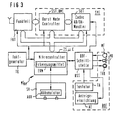
- FIG. 3 shows, starting from the cordless mobile part MT according to FIG. 1, a modified, expanded cordless mobile part MT me , which has detection means EKM for recognizing the "battery exhausted" state.
- the detection means EKM are contained in the central control ZS and bidirectionally connected to the battery AKK via the connection between the central control ZS and the power supply SV.
- the EKM detection means comprise a power supply SV downstream spreader SPE (Level Shifter), an averaging device connected downstream of the spreading device SPE MTE and one of the averaging device MTE downstream control device STE.
- the control device STE finds the actual detection of the state "Accumulator exhausted" instead.
- the control device STE has a determination module EMM, a comparison module VGM, a memory SP and a display controller AZS.
- the Functioning of the detection means EKM is related explained with FIG 5.
- FIG 5 shows a discharge voltage curve starting from FIG ESK of the AKK accumulator.
- the detection means EKM begin to calculate the curvature KRU.
- the point in time t kr and the voltage value U kr are chosen such that the "voltage knee" of the discharge voltage curve ESK can be evaluated by the curvature calculation for any given discharge voltage curve ESK of the battery AKK. It is therefore endeavored to place the starting time for the calculation of the curvature KRU of the discharge voltage curve ESK as close as possible to the location of the discharge voltage curve ESK at which the "voltage knee" begins. This has the advantage that the calculation is not unnecessarily carried out before the voltage range that is actually of interest.
- the voltage range to be evaluated of the discharge voltage curve ESK is spread in relation to the voltage values for better evaluation of the discharge states of the battery AKK by the spreading device SPE.
- An analog / digital averaging is then carried out in the averaging device MTE.
- the determination module EMM of the control device STE determines actual curvature values IKW, which it transmits to the comparison module VGM.
- the comparison module VGM is also supplied with a desired curvature value SKW stored in the memory SP, so that the comparison module VGM can compare the two curvature values IKW, SKW with one another.
- the display control AE is activated by the display control AZS via the BOF interface BSS to display the state "accumulator exhausted".
- the display control AZS via the BOF interface BSS to display the state "accumulator exhausted".
Landscapes
- Engineering & Computer Science (AREA)
- Signal Processing (AREA)
- General Physics & Mathematics (AREA)
- Physics & Mathematics (AREA)
- Chemical Kinetics & Catalysis (AREA)
- General Chemical & Material Sciences (AREA)
- Computer Networks & Wireless Communication (AREA)
- Electrochemistry (AREA)
- Chemical & Material Sciences (AREA)
- Manufacturing & Machinery (AREA)
- Power Engineering (AREA)
- Secondary Cells (AREA)
- Charge And Discharge Circuits For Batteries Or The Like (AREA)
- Mobile Radio Communication Systems (AREA)
- Tests Of Electric Status Of Batteries (AREA)
Abstract
Description


Claims (13)
- Verfahren zum Anzeigen des Zustands "Energiespeicher erschöpft" in Elektro-Geräten mit Elektro-Energiespeichern, mit folgenden Verfahrensschritten:(a) Während der Entladephase des Elektro-Energiespeichers (AKK) wird eine die Krümmung einer Entladekurve (ESK) des Energiespeichers (AKK) angebende Kenngröße (KRU) in Form eines krümmungsbezogenen Istwertes (IKW) ermittelt,(b) die Kenngröße (KRU) wird durch lineare Regression ermittelt,(c) Definieren eines krümmungsbezogenen Sollwertes (SKW),(d) Vergleichen des Istwertes (IKW) mit dem Sollwert (SKW),(e) Anzeigen des Zustands "Energiespeicher erschöpft", wenn der Istwert (IKW) den Sollwert (SKW) unter-/überschreitet.
- Verfahren nach Anspruch 1, dadurch gekennzeichnet, daß die Kenngröße (KRU) kontinuierlich in regelmäßigen Zeitabständen ermittelt wird.
- Verfahren nach Anspruch 1 oder 2, dadurch gekennzeichnet, daß die Kenngröße (KRU) beim Unterschreiten eines vorgegebenen Entladekurvenwertes (Ukr) ermittelt wird, wobei der Entladekurvenwert (Ukr) derart vorgegeben wird, daß ein Zeitpunkt (tkr), an dem der Entladekurvenwert (Ukr) unterschritten wird, in der Nähe des Zeitpunktes liegt, bei dem ein "Spannungsknie" der Entladekurve (ESK) einsetzt.
- Verwendung des Verfahrens nach einem der Ansprüche 1 bis 3 in einem Elektro-Gerät mit einem Akkumulator (AKK) als Elektro-Energiespeicher.
- Verwendung des Verfahrens nach einem der Ansprüche 1 bis 3 in einem Elektro-Gerät mit einer Batterie als Elektro-Energiespeicher.
- Verwendung des Verfahrens nach einem der Ansprüche 1 bis 5 in einem Schnurlos-Mobilteil (MTme).
- Elektro-Gerät mit einem Elektro-Energiespeicher zum Anzeigen des Zustands "Energiespeicher erschöpft" mit folgenden Merkmalen:(a) ersten Mitteln (SPE, MTE, EMM) zum Ermitteln von Daten, die während der Entladephase des Elektro-Energiespeichers (AKK eine die Krümmung einer Entladekurve (ESK) des Energiespeichers (AKK) angebende Kenngröße (KRU) in Form eines krümmungsbezogenen Istwertes (IKW) ermitteln,(b) die ersten Mittel (SPE, MTE, EMM) sind derart ausgebildet, daß die Kenngröße (KRU) durch lineare Regression ermittelt wird,(c) einem Speicher (SP), in dem ein vorgegebener, krümmungsbezogener Sollwert (SKW) gespeichert ist,(d) zweiten Mitteln (VGM) zum Vergleichen von Daten, die mit. den ersten Mitteln (EMM) und dem Speicher (SP) verbunden sind und die den Istwert (IKW) mit dem Sollwert (SKW) vergleichen,(e) dritten Mitteln (AZS) zum Anzeigen von Daten, die mit den zweiten Mitteln (VGM) und einer Anzeigeeinrichtung (AE) verbunden sind und die den Zustand "Energiespeicher erschöpft" dann anzeigen, wenn der Istwert (IKW) den Sollwert (SKW) unter-/überschreitet.
- Elektro-Gerät nach Anspruch 7, dadurch gekennzeichnet, daß die ersten bis dritten Mittel (SPE, MTE, EMM, VGM, AZS) und der Speicher (SP) in einem Mikrocontroller (ZS, µC) integriert und implementiert sind.
- Elektro-Gerät nach Anspruch 7 oder 8, dadurch gekennzeichnet, daß die ersten Mittel (SPE, MTE, EMM) derart ausgebildet sind, daß die Kenngröße (KRU) kontinuierlich in regelmäßigen Zeitabständen ermittelt wird.
- Elektro-Gerät nach einem der Ansprüche 7 bis 9, dadurch gekennzeichnet, daß die ersten Mittel (SPE, MTE, EMM) derart ausgebildet sind, daß die Kenngröße (KRU) beim Unterschreiten eines vorgegebenen Entladekurvenwertes (Ukr) ermittelt wird, wobei der Entladekurvenwert (Ukr) derart vorgegeben wird, daß ein Zeitpunkt (tkr), an dem der Entladekurvenwert (Ukr) unterschritten wird, in der Nähe des Zeitpunktes liegt, bei dem ein "Spannungsknie" der Entladekurve (ESK) einsetzt.
- Elektro-Gerät nach einem der Ansprüche 7 bis 10, dadurch gekennzeichnet, daß der Elektro-Energiespeicher als Akkumulator (AKK) ausgebildet ist.
- Elektro-Gerät nach einem der Ansprüche 7 bis 10, dadurch gekennzeichnet, daß der Elektro-Energiespeicher als Batterie ausgebildet ist.
- Elektro-Gerät nach einem der Ansprüche 7 bis 12, dadurch gekennzeichnet, daß das Elektro-Gerät ein Schnurlos-Mobilteil (MTme) ist.
Applications Claiming Priority (3)
| Application Number | Priority Date | Filing Date | Title |
|---|---|---|---|
| DE19547019 | 1995-12-15 | ||
| DE19547019A DE19547019C2 (de) | 1995-12-15 | 1995-12-15 | Verfahren zum Anzeigen des Zustands "Energiespeicher erschöpft" in Elektro-Geräten mit Elektro-Energiespeichern und Elektro-Geräte mit Elektro-Energiespeichern zum Anzeigen des Zustands "Energiespeicher erschöpft" |
| PCT/DE1996/002396 WO1997022887A2 (de) | 1995-12-15 | 1996-12-12 | Verfahren zum anzeigen des zustands 'energiespeicher erschöpft' in elektro-geräten mit elektro-energiespeichern und elektro-geräte mit elektro-energiespeichern zum anzeigen des zustands 'energiespeicher erschöpft' |
Publications (2)
| Publication Number | Publication Date |
|---|---|
| EP0866979A2 EP0866979A2 (de) | 1998-09-30 |
| EP0866979B1 true EP0866979B1 (de) | 2002-04-03 |
Family
ID=7780307
Family Applications (1)
| Application Number | Title | Priority Date | Filing Date |
|---|---|---|---|
| EP96946076A Expired - Lifetime EP0866979B1 (de) | 1995-12-15 | 1996-12-12 | Verfahren zum anzeigen des zustands "energiespeicher erschöpft" in elektro-geräten mit elektro-energiespeichern und elektro-geräte mit elektro-energiespeichern zum anzeigen des zustands "energiespeicher erschöpft" |
Country Status (6)
| Country | Link |
|---|---|
| US (1) | US6121754A (de) |
| EP (1) | EP0866979B1 (de) |
| JP (1) | JP3699484B2 (de) |
| CN (1) | CN1125348C (de) |
| DE (2) | DE19547019C2 (de) |
| WO (1) | WO1997022887A2 (de) |
Families Citing this family (8)
| Publication number | Priority date | Publication date | Assignee | Title |
|---|---|---|---|---|
| CN2906637Y (zh) * | 2006-01-25 | 2007-05-30 | 江显灿 | 一种电动自行车的电池电量检测装置 |
| US7723958B2 (en) * | 2006-03-31 | 2010-05-25 | Valence Technology, Inc. | Battery charge indication methods, battery charge monitoring devices, rechargeable batteries, and articles of manufacture |
| US8264203B2 (en) * | 2006-03-31 | 2012-09-11 | Valence Technology, Inc. | Monitoring state of charge of a battery |
| EP2075871B1 (de) * | 2007-12-17 | 2013-02-13 | Guido Zielke | Verfahren zur Identifikation und Qualitätsdokumentation von Akkumulatoren sowie Akkumulator für Industriewerkzeuge |
| WO2011028848A1 (en) * | 2009-09-01 | 2011-03-10 | Lp Partners, Inc. | Ip based microphone and intercom |
| CN106646263A (zh) * | 2017-01-16 | 2017-05-10 | 珠海市魅族科技有限公司 | 电量计量方法及装置 |
| CN108879862B (zh) * | 2018-07-26 | 2021-08-27 | 浙江慧众智能装备科技有限公司 | 一种动力电池充电监测系统的控制方法 |
| DE102021001939A1 (de) * | 2020-05-05 | 2021-11-11 | Sew-Eurodrive Gmbh & Co Kg | Elektrisches Fahrzeug und Verfahren zum Betreiben eines elektrischen Fahrzeugs |
Family Cites Families (11)
| Publication number | Priority date | Publication date | Assignee | Title |
|---|---|---|---|---|
| DE3818034A1 (de) * | 1988-05-27 | 1989-11-30 | Werner Dipl Ing Wallrafen | Messgeraet zur anzeige des batterie-innenwiderstandes |
| JPH0799384B2 (ja) * | 1988-09-13 | 1995-10-25 | 日本電気株式会社 | 電池残量表示装置 |
| US5027294A (en) * | 1989-01-27 | 1991-06-25 | Zenith Data Systems Corporation | Method and apparatus for battery-power management using load-compensation monitoring of battery discharge |
| US5166623A (en) * | 1991-03-04 | 1992-11-24 | Motorola, Inc. | Method for indicating battery capacity |
| US5278509A (en) * | 1992-02-03 | 1994-01-11 | At&T Bell Laboratories | Method for monitoring battery discharge by determining the second derivative of battery voltage over time |
| US5341503A (en) * | 1992-04-16 | 1994-08-23 | International Business Machines Corporation | Battery operated computer having improved battery gauge and system for measuring battery charge |
| FR2694660B1 (fr) * | 1992-08-05 | 1994-10-07 | Merlin Gerin | Dispositif de détection de défaillance d'éléments de batterie. |
| DE4236811C1 (de) * | 1992-10-30 | 1994-01-13 | Siemens Ag | Verfahren zum Laden von Akkumulatoren in schnurlosen Kommunikationsendeinrichtungen und Anordnung zur Durchführung des Verfahrens |
| US5455499A (en) * | 1993-04-26 | 1995-10-03 | Motorola, Inc. | Method and apparatus for indicating a battery status |
| US5721482A (en) * | 1996-01-16 | 1998-02-24 | Hewlett-Packard Company | Intelligent battery and method for providing an advance low battery warning for a battery powered device such as a defibrillator |
| JP3454657B2 (ja) * | 1997-01-30 | 2003-10-06 | 三洋電機株式会社 | 二次電池の残存容量検出方法 |
-
1995
- 1995-12-15 DE DE19547019A patent/DE19547019C2/de not_active Expired - Lifetime
-
1996
- 1996-12-12 JP JP52241697A patent/JP3699484B2/ja not_active Expired - Lifetime
- 1996-12-12 DE DE59609035T patent/DE59609035D1/de not_active Expired - Fee Related
- 1996-12-12 EP EP96946076A patent/EP0866979B1/de not_active Expired - Lifetime
- 1996-12-12 US US09/077,708 patent/US6121754A/en not_active Expired - Lifetime
- 1996-12-12 WO PCT/DE1996/002396 patent/WO1997022887A2/de not_active Ceased
- 1996-12-12 CN CN96199874A patent/CN1125348C/zh not_active Expired - Lifetime
Also Published As
| Publication number | Publication date |
|---|---|
| JPH11502029A (ja) | 1999-02-16 |
| WO1997022887A3 (de) | 1997-07-31 |
| DE19547019C2 (de) | 2000-05-31 |
| JP3699484B2 (ja) | 2005-09-28 |
| CN1125348C (zh) | 2003-10-22 |
| WO1997022887A2 (de) | 1997-06-26 |
| DE59609035D1 (de) | 2002-05-08 |
| EP0866979A2 (de) | 1998-09-30 |
| DE19547019A1 (de) | 1997-06-19 |
| US6121754A (en) | 2000-09-19 |
| CN1208469A (zh) | 1999-02-17 |
Similar Documents
| Publication | Publication Date | Title |
|---|---|---|
| DE69031090T2 (de) | Vorrichtung zur Bestimmung des Batterietyps und Modifikation der Betriebsmerkmale | |
| DE19644955C2 (de) | Elektronisches Gerät | |
| EP3701584B1 (de) | Verfahren zum auf- oder entladen eines energiespeichers | |
| EP3444888B1 (de) | Vorrichtung und verfahren zur batterieverwaltung | |
| DE10320901B4 (de) | Verfahren zum Bestimmen eines Ladezustands von Batterien, insbesondere von Blei-Säure-Batterien, in einem Hybridelektrofahrzeug | |
| DE10035959A1 (de) | Verfahren zum Entladen einer Vielzahl von wiederaufladbaren Batterien und Batteriebaugruppe | |
| EP2849309A1 (de) | Vorrichtung und verfahren zur steuerung des betriebs zum ausgleich der ladungskapazität von sekundärbatteriezellen | |
| EP0866979B1 (de) | Verfahren zum anzeigen des zustands "energiespeicher erschöpft" in elektro-geräten mit elektro-energiespeichern und elektro-geräte mit elektro-energiespeichern zum anzeigen des zustands "energiespeicher erschöpft" | |
| DE102015111128A1 (de) | Energieversorgungsgerät | |
| DE102009031828A1 (de) | Batterieladestatusanzeige für ein Benutzerendgerät | |
| DE4439261C2 (de) | Schnurloses Telefonsystem | |
| DE102015008603A1 (de) | Batteriepack und Verfahren zum Steuern desselben | |
| CN108550928A (zh) | 电动汽车、充放电设备、电池soh的检测方法及系统 | |
| JP2010119186A (ja) | 充電式リチウム電池の充電システム | |
| CN109709489A (zh) | 一种计算电池功率限值的方法及系统 | |
| DE102004043531A1 (de) | Batteriepaket, mit einem Batteriepaket verbindbares Elektrogerät und Verfahren zum Identifizieren eines Batteriepaket-Typs | |
| DE602004012115T2 (de) | Verfahren und Vorrichtung zur Ermittlung der Kapazität einer Batterie. | |
| KR20040071248A (ko) | 이차 전지의 출력 제어 장치 및 방법, 전지 팩 시스템, 및전동 차량 | |
| CN110364776B (zh) | 一种锂电池智能充电管理方法及其装置 | |
| EP3618219A1 (de) | Verfahren zur wiederherstellung eines tiefentladenen batteriemoduls sowie zugehöriges, unterbrechungsfreies stromversorgungssystem | |
| KR20180089698A (ko) | 배터리 충방전 제어 장치 및 그 충방전 제어 방법 | |
| DE102014222039A1 (de) | Vorrichtung einer Fahrzeugenergiequelle | |
| CN112744084B (zh) | 扭矩控制方法及其装置、车辆、电子设备和存储介质 | |
| AT515034B1 (de) | Vorrichtung zur Ansteuerung elektrischer Energiespeicher | |
| DE19852069C1 (de) | Verfahren zum Erkennen von Fehlerzuständen eines Akkumulators |
Legal Events
| Date | Code | Title | Description |
|---|---|---|---|
| PUAI | Public reference made under article 153(3) epc to a published international application that has entered the european phase |
Free format text: ORIGINAL CODE: 0009012 |
|
| 17P | Request for examination filed |
Effective date: 19980608 |
|
| AK | Designated contracting states |
Kind code of ref document: A2 Designated state(s): DE ES FR GB IT |
|
| GRAG | Despatch of communication of intention to grant |
Free format text: ORIGINAL CODE: EPIDOS AGRA |
|
| GRAG | Despatch of communication of intention to grant |
Free format text: ORIGINAL CODE: EPIDOS AGRA |
|
| GRAH | Despatch of communication of intention to grant a patent |
Free format text: ORIGINAL CODE: EPIDOS IGRA |
|
| 17Q | First examination report despatched |
Effective date: 20010620 |
|
| GRAH | Despatch of communication of intention to grant a patent |
Free format text: ORIGINAL CODE: EPIDOS IGRA |
|
| REG | Reference to a national code |
Ref country code: GB Ref legal event code: IF02 |
|
| GRAA | (expected) grant |
Free format text: ORIGINAL CODE: 0009210 |
|
| AK | Designated contracting states |
Kind code of ref document: B1 Designated state(s): DE ES FR GB IT |
|
| PG25 | Lapsed in a contracting state [announced via postgrant information from national office to epo] |
Ref country code: IT Free format text: LAPSE BECAUSE OF FAILURE TO SUBMIT A TRANSLATION OF THE DESCRIPTION OR TO PAY THE FEE WITHIN THE PRE;WARNING: LAPSES OF ITALIAN PATENTS WITH EFFECTIVE DATE BEFORE 2007 MAY HAVE OCCURRED AT ANY TIME BEFORE 2007. THE CORRECT EFFECTIVE DATE MAY BE DIFFERENT FROM THE ONE RECORDED.SCRIBED TIME-LIMIT Effective date: 20020403 Ref country code: GB Free format text: LAPSE BECAUSE OF FAILURE TO SUBMIT A TRANSLATION OF THE DESCRIPTION OR TO PAY THE FEE WITHIN THE PRESCRIBED TIME-LIMIT Effective date: 20020403 Ref country code: FR Free format text: LAPSE BECAUSE OF FAILURE TO SUBMIT A TRANSLATION OF THE DESCRIPTION OR TO PAY THE FEE WITHIN THE PRESCRIBED TIME-LIMIT Effective date: 20020403 |
|
| REF | Corresponds to: |
Ref document number: 59609035 Country of ref document: DE Date of ref document: 20020508 |
|
| GBV | Gb: ep patent (uk) treated as always having been void in accordance with gb section 77(7)/1977 [no translation filed] |
Effective date: 20020403 |
|
| PG25 | Lapsed in a contracting state [announced via postgrant information from national office to epo] |
Ref country code: ES Free format text: LAPSE BECAUSE OF FAILURE TO SUBMIT A TRANSLATION OF THE DESCRIPTION OR TO PAY THE FEE WITHIN THE PRESCRIBED TIME-LIMIT Effective date: 20021030 |
|
| EN | Fr: translation not filed | ||
| PLBE | No opposition filed within time limit |
Free format text: ORIGINAL CODE: 0009261 |
|
| STAA | Information on the status of an ep patent application or granted ep patent |
Free format text: STATUS: NO OPPOSITION FILED WITHIN TIME LIMIT |
|
| 26N | No opposition filed |
Effective date: 20030106 |
|
| PG25 | Lapsed in a contracting state [announced via postgrant information from national office to epo] |
Ref country code: DE Free format text: LAPSE BECAUSE OF NON-PAYMENT OF DUE FEES Effective date: 20030701 |