EP0866763B1 - Propeller configuration for sinusoidal waterline ships - Google Patents
Propeller configuration for sinusoidal waterline ships Download PDFInfo
- Publication number
- EP0866763B1 EP0866763B1 EP96944140A EP96944140A EP0866763B1 EP 0866763 B1 EP0866763 B1 EP 0866763B1 EP 96944140 A EP96944140 A EP 96944140A EP 96944140 A EP96944140 A EP 96944140A EP 0866763 B1 EP0866763 B1 EP 0866763B1
- Authority
- EP
- European Patent Office
- Prior art keywords
- ship
- propeller
- plane
- hull
- dwl
- Prior art date
- Legal status (The legal status is an assumption and is not a legal conclusion. Google has not performed a legal analysis and makes no representation as to the accuracy of the status listed.)
- Expired - Lifetime
Links
Images


Classifications
-
- B—PERFORMING OPERATIONS; TRANSPORTING
- B63—SHIPS OR OTHER WATERBORNE VESSELS; RELATED EQUIPMENT
- B63B—SHIPS OR OTHER WATERBORNE VESSELS; EQUIPMENT FOR SHIPPING
- B63B1/00—Hydrodynamic or hydrostatic features of hulls or of hydrofoils
- B63B1/02—Hydrodynamic or hydrostatic features of hulls or of hydrofoils deriving lift mainly from water displacement
- B63B1/04—Hydrodynamic or hydrostatic features of hulls or of hydrofoils deriving lift mainly from water displacement with single hull
- B63B1/08—Shape of aft part
-
- B—PERFORMING OPERATIONS; TRANSPORTING
- B63—SHIPS OR OTHER WATERBORNE VESSELS; RELATED EQUIPMENT
- B63H—MARINE PROPULSION OR STEERING
- B63H5/00—Arrangements on vessels of propulsion elements directly acting on water
- B63H5/07—Arrangements on vessels of propulsion elements directly acting on water of propellers
- B63H5/08—Arrangements on vessels of propulsion elements directly acting on water of propellers of more than one propeller
-
- B—PERFORMING OPERATIONS; TRANSPORTING
- B63—SHIPS OR OTHER WATERBORNE VESSELS; RELATED EQUIPMENT
- B63B—SHIPS OR OTHER WATERBORNE VESSELS; EQUIPMENT FOR SHIPPING
- B63B1/00—Hydrodynamic or hydrostatic features of hulls or of hydrofoils
- B63B1/02—Hydrodynamic or hydrostatic features of hulls or of hydrofoils deriving lift mainly from water displacement
- B63B1/04—Hydrodynamic or hydrostatic features of hulls or of hydrofoils deriving lift mainly from water displacement with single hull
- B63B1/06—Shape of fore part
- B63B1/063—Bulbous bows
-
- B—PERFORMING OPERATIONS; TRANSPORTING
- B63—SHIPS OR OTHER WATERBORNE VESSELS; RELATED EQUIPMENT
- B63B—SHIPS OR OTHER WATERBORNE VESSELS; EQUIPMENT FOR SHIPPING
- B63B1/00—Hydrodynamic or hydrostatic features of hulls or of hydrofoils
- B63B1/02—Hydrodynamic or hydrostatic features of hulls or of hydrofoils deriving lift mainly from water displacement
- B63B1/04—Hydrodynamic or hydrostatic features of hulls or of hydrofoils deriving lift mainly from water displacement with single hull
- B63B1/06—Shape of fore part
- B63B2001/066—Substantially vertical stems
-
- Y—GENERAL TAGGING OF NEW TECHNOLOGICAL DEVELOPMENTS; GENERAL TAGGING OF CROSS-SECTIONAL TECHNOLOGIES SPANNING OVER SEVERAL SECTIONS OF THE IPC; TECHNICAL SUBJECTS COVERED BY FORMER USPC CROSS-REFERENCE ART COLLECTIONS [XRACs] AND DIGESTS
- Y02—TECHNOLOGIES OR APPLICATIONS FOR MITIGATION OR ADAPTATION AGAINST CLIMATE CHANGE
- Y02T—CLIMATE CHANGE MITIGATION TECHNOLOGIES RELATED TO TRANSPORTATION
- Y02T70/00—Maritime or waterways transport
- Y02T70/10—Measures concerning design or construction of watercraft hulls
Definitions
- conventional hull configurations can obtain greater deadweight tonnage by increasing the fullness of the underwater portion of the hull, thereby increasing the total displacement.
- the beam of the hull can be increased to obtain a greater moment on inertia at the waterline, optionally also raising the volumetric center of gravity of the underwater hull.
- This configuration has a large flat oblique surface that extends from the stern at the waterline down to the keel line at the midship. This surface encompasses the whole aft section of the ship and is angled downward from the stern toward the bow.
- the first Ramform ship built under the original patent is designed with an angle of 14.2 degrees between the oblique plane and the base plane. Originally, it was believed that the water flowlines in the aft section would run parallel to this surface rather than parallel to the waterline. However, now it is observed that the flowlines separate from the oblique plane so that the wake of this ship contains vortices which shed from the wide, sloping aftship. This effect is caused by the steep angle of 14.2 degrees between the two planes, so that the flow in the boundary layer separates and reverses direction near the oblique plane of the bottom, resulting in the generation of vortices.
- the propulsion system disclosed in the Ramde European '767 patent was designed to accommodate angled flow lines which remained attached to the oblique plane.
- the axis of the propeller (f) is shown substantially parallel to the approximately oblique surface (s). This angled orientation was believed to increase the overall thrust of the propeller because the propeller race was in line with the water flow lines. This was to allow unstable flow from the propeller to remain attached to oblique surface. If the unstable flow separates from the oblique surface, drag or resistance is significantly increased. This design was to produce greater overall thrust in spite of the smaller horizontal thrust component cause by the inclined installation of the propeller.
- EP-A-0678445 discloses a hull configuration providing homogenous flow of water under the stern including side hull bulges that are relatively constant in size from the bow to the mid-ship and tapering off to about zero at the stern. Additionally the hull is provided with a slope surface forming an angle of below 14° between the base line of the ship near mid-ship and a line extending from that point to another point on the surface to about 0.2L from the stern, where L is the length of the ship.
- the present invention places propellers near the corners of the stern rather than in the center of the oblique surface. Tests have revealed that regions near the stern corners have reduced hull wake and that the water flowlines are parallel with the base plane rather than the oblique surface. Therefore, propellers attached to the ship at the stern corners may be parallel with the base plane of the ship to impart the entire thrust component in the direction of the ship's forward motion. Also, the angle of the oblique surface is modified to ensure that the flow lines do not separate from the oblique surface near the center of the ship in the absence of propellers which had been positioned there.
- a ship of a displacement type with a pointed bow, a transom stern , a longitudinal length of L, and defining a base plane, a design waterline plane, and a centre plane comprising:
- a hull 10 with more rounded lines than conventional hull configurations expressed by the term for slenderness of line L/V 1/3 , where L is the length of the hull at the design waterline (dwl) corresponding to the depth T to the summer freeboard (see Fig. 2), and V is the displacement volume of the hull at the design waterline.
- L/V 1/3 is about 3 or greater, but the specific resistance to propulsion compared to conventional hull configurations is not increased.
- the present embodiment provides that the hull beam B is such that the L/B ratio is between about 1 and about 2.2. The preferred ratio has been found to be about 1.7.
- B is the maximum beam of the hull at the design waterline (dwl).
- the height of the metacenter of the hull 10 is more than doubled in relation to conventional hull configurations of the same length.
- the displacement distribution in the longitudinal direction approximates a Rayleigh wave.
- a wave is accomplished in the present embodiment with substantially squarely cut off, approximately harmonic sinusoidal waterlines (Figure 2: dwl, 1, 2, 3) with extremity or stationary points 12 and 14 at the ends of the hull fore and aft, while at the same time the base lines of the waterlines (O dwl , 0 1 , 0 2 , 0 3 ) from the design waterline (dwl) and at increasing depths from this gradually are displaced in the direction of forward propulsion, shortened so far that an approximately oblique surface (s), which may be straight, is defined.
- surface (s) which comprises the stern half of the hull 10 and permits utilization of various propulsion systems.
- a ratio B1/t1 is defined at a transverse section through the hull 10 below the design waterline (dwl) at a distance of about 0.15 L from the stern, wherein (B1) is the beam at the design waterline (dwl) and (t1) is the draught of the hull (measured from the same waterline).
- the ratio B1/t1 is about 15.
- the ratio B1/t1 is greater than the corresponding ratio for a section at L/2 where the beam (B 2 ) and draught (t 2 ) are measured in the same way.
- the hull parameter e is about 1 or greater.
- the hull 10 is shown with the approximately harmonic sinusoidal waterlines around the design waterline (dwl) with extremity points around the hull's bow and stern ends with, wherein the areal center of gravity (LCF) is about 0.2 L aft of L/2.
- LCF areal center of gravity
- Figure 2 shows the an embodiment of the invention's hull below the design waterline (dwl) in vertical section, where it is seen that the base lines are substantially squarely cut off.
- the distance between the areal center of gravity (LCF) and the buoyancy center of gravity (LCB) of the hull 10 at the depth of the design waterline (dwl) is about 0.075L.
- the generally planar surface (s) in some embodiments takes the form of a curved surface with a very large radius, (for example between about 3 and about 5 times the maximum beam, and in a specific embodiment, about 4)
- the hull configuration of Figure 2 is shown in horizontal projection with the waterlines dwl, 1, 2, 3 and g in the examples with a U-frame at the bow end of the hull. According to alternative embodiments of the invention, other known frame forms are used.
- the embodiment of Figure 3 also has a ratio between beam and depth for a section around 0.15L from the stern and at L/2, where the respective beams and depths are designated B 1 and B 2 and t 1 and t 2 .
- the Froude Number is defined as V/(gL) 1 ⁇ 2 where V is the speed of the ship, g is the gravitational acceleration constant, and L is the length of the ship.
- the Froude Number rather than the ship's absolute speed, defines whether a ship is fast or slow. Thus, two ships may have the same absolute speed and one of them could be a fast ship and the other a slow one, since the former may be short and the latter much longer. It is desirable to have a ship with a Froude Number between about 0.1 and about 0.35. Thus, even though the ship outlined above has a relatively low L/B ratio, which tends to increase the resistance, it should be between about 0.1 and about 0.35.
- a base plane (B) and an oblique plane (O) are shown.
- the base plane (B) is parallel to the design water line (dwl) and coincides with the keel line (K) of the ship.
- a surface (S) extends from the transom stern (700) at the design waterline plane (dwl) to the base plane (B) at about L/2.
- the oblique plane (O) intersects the transom stern (700) at the design waterline plane (dwl) and a point located on the surface (S) at about 0.2L from the transom stern (700).
- the angle between the oblique plane (O) and the base plane (B) is defined as alpha ( ⁇ ).
- the angle ( ⁇ ) dictates whether the water flowlines over the surface (S) remain attached to the surface (S) or whether the flowlines become separated. At smaller angles the flowlines do not separate from the surface (S) of the ship. If the flowlines do separate from the surface (S), then vortices are formed at the region of separation which increases the ships resistance. Tests were performed to determine the angle which provides the lowest resistance.
- a ship was tested in a model basin with respect to the effect of the variation in angle between the oblique plane and the base plane on model resistance.
- a resistance test was run with constant draught at F.P. and the dynamic suction in F.P. was measured at speeds 13 - 17 knots.
- the hull model M-1867 C was manufactured to the scale ratio 1:26.5.
- the model was equipped with a trip wire at station 9-1/2 in order to obtain turbulent flow. Stabilizing fins and thruster pods were not fitted to the model. All results refer to salt water with density 1025 kp/m 3 and a sea temperature of 15°C.
- a sinusoidal waterline hull having a L/B ratio of about 1.7 could still have a Froude Number of about 0.32 by adjusting the angle between the oblique plane and the base plane to be about 12.2°.
- Figure 5 represents a schematic diagram of a transversal cross section of a sinusoidal waterline-type hull ship according to the present invention showing the principal transition curves shipside-bottom cross sections for a conventional ship which is represented by a dotted line and a sinusoidal waterline-type hull ship represented by the full line with a horizontally extending bulge.
- a conventional ship which is represented by a dotted line
- a sinusoidal waterline-type hull ship represented by the full line with a horizontally extending bulge.
- the center line plane 1 which is used as reference line to determine the beam of the ship at various heights of the transversal cross section.
- the hull of a conventional ship comprises a side board plane which is substantially parallel to the center line plane 1 and which runs into the bottom plane by a curved portion connecting the side board plane with the bottom plane of the ship.
- This curved portion is defined by a radius related to a imaginary point P constructed by the intersection of an elongated line lying in the side board plane and an elongated line lying in the bottom plane 2.
- This point P also corresponds to the maximum beam of a conventional ship characterized by B max , conv .
- the side board plane is parallel to the center line plane 1 in the area of the waterline 3 in the midship section of a conventional ship.
- a sinusoidal waterline-type hull 10 significantly deviates from the general shape of a conventional hull form.
- the hull 10 is curved at a certain radius in a concave way related to the center line plane 1 and running into a bulge 100 near the bottom plane 2, said bulge 100 going beyond the line through the side board plane and point P, which defines the maximum beam of a conventional ship B max, conv so that the maximum beam of a sinusoidal waterline-type hull ship is larger, by the difference between B max, conv and B max, sin than B max, conv .
- Such a bulge 100 which is arranged below the waterline 3 and which has smooth transition ranges from the side board of the ship into the bulge 100 and from the bulge into the bottom plane 2, increases the deadweight of the ship as well as the rolling, pitching and to a certain extent also heaving movements of the ship.
- the amount of improvement of the rolling behavior of a sinusoidal waterline-type hull ship without a bulge is rather limited because the water displaced by the hull form in the bottom plane range of the ship can easily flow transversely around the bulge 100 without giving a significant reduction of rolling behavior of the ship.
- Figure 6 comprises a schematic diagram of a cross section of an improved sinusoidal waterline-type hull ship according to Figure 5.
- This sinusoidal waterline-type hull ship comprises a horizontally and vertically extending bulge 200 according to the invention.
- the construction of point P corresponds to the one described with regard to Figure 5.
- the bulge 200 encircles this point P both in horizontal and in vertical direction.
- this point P represents the locus at which the local extension of the basically vertical ship side, the side board plane, and the basically horizontal bottom of the ship intersect.
- the bulge 200 goes below the bottom plane 2 of the ship and comprises transition portions 5, i.e. the transition curves between the portion of the bulge 200 approaching the bottom plane 2 of the ship.
- the transition curves 5 comprise a steeper or a flatter transition region.
- the bulge 200 extending also in vertical direction beyond the bottom plane 2 increases the deadweight of the ship significantly and on the other hand significantly improves mainly the rolling capability of the ship.
- This rolling improvement results from the fact that, when the ship is rolling in seawaves, the water flowing around the hull in the bottom plane region 2 transversely from the center line of the ship towards the bulge 200 is forced downwards and hence, generating a lift component to the ship which related to the center line plane of the ship corresponds to a moment directed upwards.
- the bulge 200 In order to ensure that, nowhere on the hull of the ship, the bulge 200 goes below the keel line which is important from the point of view of docking the ship without giving rise to damage to the hull during the docking operation, the bulge 200 starts from a zero vertical extension at the area of about L/3 from the bow and gradually increases towards the transom stern 7 of the ship.
- Figure 7 represents a bottom plane view of half a hull according to Figure 5 made with a bulge 200 running from the bow of the ship up to the transom stern 7.
- This Figure indicates that the vertical extension of the bulge 200 can already start at the bow region of the ship and gradually increase therefrom to the transom stern.
- the line inside the bottom view represented in Figure 7 represents the point at the respective cross section where the bulge 200 runs into the bottom plane 2. That means the line shown represents a tangent line of the locus, where the bulge 200 runs into the bottom plane, that means that in the range L/3 from forward perpendicular FP of the ship, the only horizontally extending bulge runs into the bottom plane 2 of the ship at a point inside the distance between the center line plane of the ship and point P.
- the vertical extension of the bulge 200 starts, for the reasons mentioned with regard to Figure 6, approximately at a point L/3 of the ship and gradually increases towards the transom stern.
- the width of the bulge 200, where the bulge comprises also a vertical extension with regard to the bottom plane 2 is preferably in a range defined by the ratio b/B approximately 0.5 to 0.8.
- the term b stands for the distance from the center line plane 1 to the tangent line, where the vertical extending bulge 200 runs into the bottom plane 2, whereas B represents the maximum width of the ship at this particular cross section, that means the distance between the center line plane 1 of the ship and the maximum beam including the horizontal extension of the bulge 200 with regard to point P.
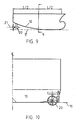
- Figure 8 represents a sideview of the hull made according to an embodiment of the present invention.
- the hull 10 of the sinusoidal waterline-type hull ship comprises a bulbous bow going in forward direction beyond forward perpendicular FP of the ship, a sloped surface 6 starting from about L/3 to the transom stern 7 of the ship. At a cross section forward perpendicular, the tangent line coincides with the center line of the bulbous bow 4.
- the bulge 200 is shown extending from and below surface 6.
- Hull wake describes a phenomenon wherein water particles flowing around the hull have vector components in the same direction as the forward motion of the ship.
- propeller placement it is important to know the speed of the water through the space occupied by the propeller relative to the ship.
- W T is nearly one (1)
- the water particles moving through the propeller disc have forward components nearly as great as the ship. This is undesirable.
- W T is nearly zero (0), then the forward vector components of the water particles are almost non existent. Therefore, it is best to position the propellers where W T is nearly zero (0).
- a propeller is positioned below the oblique surface (10) near a corner of the stern of the ship.
- a second propeller (30) is also positioned below the oblique surface (10) near the opposite corner of the stern of the ship.
- Tests were performed to determine the magnitude of the hull wake at the stern corners.
- the pitot-tube measures the velocity of the water particles through the propeller disc.
- the pitot-tube wake survey was undertaken by moving the pitot-tube systematically over the propeller disc area.
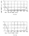
- test results for the Taylor Wake are provided for angular positions at radii ranging from 40mm to 100mm, respectively relative to the scale model.
- the data from the graphs in Figures 12a - 12d are incorporated into a curve of constant wake fractions for the propeller disc shown in Figure 13. As shown in Figure 13, there is no hull wake across most of the propeller disc. Only between 330° and 30° is there a slight hull wake and even here the wake fraction is less than 0.2. This means that a propeller which is attached to the hull of the ship at this location runs through water flowlines that are nearly undisturbed by the ship's hull.
- the central axis (21) of the propeller (20) is parallel to the base plane (11) of the ship. This serves two purposes: first, the entire thrust vector of the propeller is in the forward direction of the ship; and second, the axis (21) of the propeller (20) can be swivelled 360° to direct the thrust vector in any direction parallel to the base plane (11) of the ship. With the entire thrust component oriented in the direction of the ship's forward motion more efficiently utilizes the power necessary to propel the ship.
- propellers (20) and (30) are shown, one in each of the stern corners below the oblique plane. This allows for improved maneuverability and control of the ship. Not only may the ship be steered by varying the thrust from the propellers (20) and (30), but the axes of the propellers (20) and (30) may be swivelled from side to side so as to provide thrust vectors transverse to the forward motion of the ship.
- the propellers (20) and (30) may be efficiently swivelled because they are operated in zones of fluid flow where there is almost no hull wake.
- a third propeller (40) is shown, which extends below the keel line near the bow. This propeller also has the ability to swivel from side to side for added maneuverability.
- Figure 14 It represents a schematic side view of a hull comprising a skeg extending in the longitudinal direction from about L/3 measured from forward perpendicular FP of the ship with regard to the length L of the ship to the transom stern 7.
- the skeg 300 corresponds to the shaded area in Figures 14 - 16.
- the general shape of the hull form of the sinusoidal waterline-type hull ship comprises a bulbous bow 4 extending in forward direction beyond forward perpendicular FP of the ship, a sloped or oblique surface 6 starting from about L/3 and running to the transom stern 7 of the ship and a base plane 2 which forms the borderline plane for the maximum vertical extension of the center skeg 300, so that the center skeg 300 has a maximum vertical extension or height which in each cross section of the ship corresponds to the center plane 2.
- Fig. 15 shows a bottom plan view according to Fig. 14 showing the longitudinal and transversal extension and shape in a principal representation of the center skeg.
- the center skeg starts with a zero vertical extension, that means at a level coinciding with the base plane 2 and gradually increasing in height, that means in vertical extension towards the transom stern 7 so that the lowermost portion of the skeg coincides with the base plane 2 at each and every cross section of the ship.
- the thickness of the skeg gradually decreases to zero value at the transom stern 7 of the ship.
- the skeg comprises skeg bulges 310 which are arranged in the lower portions of the skeg, that means in the area of the skeg adjacent to the base plane 2 without going beyond the base plane 2.
- the skeg bulges 310 tangentially run out of the substantially parallel side walls of the skeg 300 at a location of about L/3 of the ship, and gradually increase towards a maximum horizontal extension at the aft portion of the ship, from which the horizontal extension of the skeg bulges 310 gradually decrease to zero extension and therefore coinciding with the aftmost portion of the skeg 300.
- a skeg of thickness (b) it is advantageous to have a maximum horizontal extension from the starboard extension to the port extension of said skeg bulges which correspond to 2b, that means double the width or thickness of the skeg. If the beam of the ship is designated with B, the thickness of the skeg related to the beam of the ship, that means b/B is approximately 1 over 10.
- Fig. 16 represents a schematic view from the transom stern according to Fig. 14 for a sinusoidal waterline-type hull ship with a skeg including skeg bulges as well as horizontally and vertically extending hull bulges.
- This view according to Fig. 16 represents a combination of hull bulges 200 with the inventive center skeg 300 including skeg bulges 310 on either side of the skeg 300.
- the skeg 300 as well as the skeg bulges 310 result in an increased deadweight of about 20 to 30 percent of the ship without altering the overall dimensions of the ship.
- Fig. 16 represents a schematic view from the transom stern according to Fig. 14 for a sinusoidal waterline-type hull ship with a skeg including skeg bulges as well as horizontally and vertically extending hull bulges.
- This view according to Fig. 16 represents a combination of hull bulges 200 with the inventive center skeg 300 including skeg bulg
- the skeg bulges 310 tangentially run into the substantially parallel sidewalls of the center skeg 300 at the transition periods from the skeg bulges into the center skeg wall.
- Both the center skeg 300 and the hull bulges 200 alone and in combination result in a significantly improved rolling behavior of the ship.
Description
- Recently, sinusoidal water-line hulls have been developed to improve a vessel's deadweight tonnage transverse stability, navigational and sailing properties and to reduce stresses on the hull beam whether the vessel is sailing in quiet water or into the waves. An example of this type of hull is described in
European Patent 0 134 767 B1, issued to Ramde. - As explained in the Ramde patent, at given main dimensions of length, beam and draught, conventional hull configurations can obtain greater deadweight tonnage by increasing the fullness of the underwater portion of the hull, thereby increasing the total displacement. To improve the transverse stability of a conventionally formed hull, expressed as a higher initial metacenter, the beam of the hull can be increased to obtain a greater moment on inertia at the waterline, optionally also raising the volumetric center of gravity of the underwater hull.
- This configuration has a large flat oblique surface that extends from the stern at the waterline down to the keel line at the midship. This surface encompasses the whole aft section of the ship and is angled downward from the stern toward the bow. The first Ramform ship built under the original patent is designed with an angle of 14.2 degrees between the oblique plane and the base plane. Originally, it was believed that the water flowlines in the aft section would run parallel to this surface rather than parallel to the waterline. However, now it is observed that the flowlines separate from the oblique plane so that the wake of this ship contains vortices which shed from the wide, sloping aftship. This effect is caused by the steep angle of 14.2 degrees between the two planes, so that the flow in the boundary layer separates and reverses direction near the oblique plane of the bottom, resulting in the generation of vortices.
- The propulsion system disclosed in the Ramde European '767 patent was designed to accommodate angled flow lines which remained attached to the oblique plane. The axis of the propeller (f) is shown substantially parallel to the approximately oblique surface (s). This angled orientation was believed to increase the overall thrust of the propeller because the propeller race was in line with the water flow lines. This was to allow unstable flow from the propeller to remain attached to oblique surface. If the unstable flow separates from the oblique surface, drag or resistance is significantly increased. This design was to produce greater overall thrust in spite of the smaller horizontal thrust component cause by the inclined installation of the propeller.
- However, it is now observed that for particular angles of the oblique plane, unstable flow can remain attached to the oblique surface. Also, the hull wake varies at different points over the oblique surface. Therefore, there is a need for a sinusoidal water-line hull that has a propeller that is positioned in a region of reduced hull wake and that produces a larger horizontal thrust component without causing separation of the flow lines from the oblique surface.
- EP-A-0678445, discloses a hull configuration providing homogenous flow of water under the stern including side hull bulges that are relatively constant in size from the bow to the mid-ship and tapering off to about zero at the stern. Additionally the hull is provided with a slope surface forming an angle of below 14° between the base line of the ship near mid-ship and a line extending from that point to another point on the surface to about 0.2L from the stern, where L is the length of the ship.
- The present invention places propellers near the corners of the stern rather than in the center of the oblique surface. Tests have reveled that regions near the stern corners have reduced hull wake and that the water flowlines are parallel with the base plane rather than the oblique surface. Therefore, propellers attached to the ship at the stern corners may be parallel with the base plane of the ship to impart the entire thrust component in the direction of the ship's forward motion. Also, the angle of the oblique surface is modified to ensure that the flow lines do not separate from the oblique surface near the center of the ship in the absence of propellers which had been positioned there.
- According to the present invention a ship of a displacement type with a pointed bow, a transom stern , a longitudinal length of L, and defining a base plane, a design waterline plane, and a centre plane comprising:
- approximately sinusoidal waterlines; and
- a surface extending from the transom stern at the design waterline plane to the base plane at about L/2 and defining an angle between
- the base plane and an oblique plane said oblique plane defined by a line at the intersection of the transom stern and the design waterline plane, and a point located on said surface at about 0.2L from the transom stern; is characterised by
- a first propeller which is attached to said surface of the ship near a first corner of the transom stern, and
- a second propeller which is attached to said surface of the ship near a second corner of the transom stern,
-
- The present invention will be better understood by reading the following description of nonlimitative embodiments, with reference to the attached drawings which are briefly described as follows:
- Figure 1 is a top plan view of a hull made according to an embodiment of the present invention.
- Figure 2 is a side elevation of the hull of Fig. 1.
- Figure 3 is bottom plan view of the hull of Fig. 1.
- Figure 4 is a side view of a hull made according to an embodiment of the present invention.
- Figure 5 is a schematic diagram of a transverse cross-section of a bulge at the edge of the oblique surface.
- Figure 6 is a schematic diagram of a cross section of a bulge which extends both in horizontal and vertical directions.
- Figure 7 represents a bottom plane view of half a hull according to Figure 5 made with a bulge running from the bow of the ship to the transom stern.
- Figure 8 represents a sideview of the hull made according to an embodiment of the present invention.
- Figure 9 describes one embodiment of the invention shown from the starboard side.
- Figure 10 shows an aft view of an embodiment of the invention.
- Figure 11 depicts a top view of an embodiment of the invention.
- Figure 12a shows test results for the Taylor Wake for angular positions at a radius of 40mm relative to the scaled model.
- Figure 12b shows test results for the Taylor Wake for angular positions at a radius of 60mm relative to the scaled model.
- Figure 12c shows test results for the Taylor Wake for angular positions at a radius of 80mm relative to the scaled model.
- Figure 12d shows test results for the Taylor Wake for angular positions at a radius of 100mm relative to the scaled model.
- Figure 13 depicts a curve of constant wake fractions for the propeller disc.
- Figure 14 is a starboard view of an embodiment of the invention having a skeg.
- Figure 15 is a top view of an embodiment of the invention having a skeg.
- Figure 16 is an aft view of an embodiment of the invention having a skeg.
-
- It is to be noted, however, that the appended drawings illustrate only typical embodiments of the invention and are therefore not to be considered a limitation of the scope of the invention which includes other equally effective embodiments.
- Referring now to Fig. 1, according to one embodiment of the present invention, there is provided a
hull 10 with more rounded lines than conventional hull configurations, expressed by the term for slenderness of line L/V1/3, where L is the length of the hull at the design waterline (dwl) corresponding to the depth T to the summer freeboard (see Fig. 2), and V is the displacement volume of the hull at the design waterline. Further according to this embodiment, L/V1/3 is about 3 or greater, but the specific resistance to propulsion compared to conventional hull configurations is not increased. At the same time, the present embodiment provides that the hull beam B is such that the L/B ratio is between about 1 and about 2.2. The preferred ratio has been found to be about 1.7. B is the maximum beam of the hull at the design waterline (dwl). According to this embodiment, the height of the metacenter of thehull 10 is more than doubled in relation to conventional hull configurations of the same length. - According to a further embodiment of the invention, the displacement distribution in the longitudinal direction approximates a Rayleigh wave. Such a wave is accomplished in the present embodiment with substantially squarely cut off, approximately harmonic sinusoidal waterlines (Figure 2: dwl, 1, 2, 3) with extremity or
stationary points hull 10 and permits utilization of various propulsion systems. - Referring now to Figs. 2 and 3, according to a further embodiment of present invention, a ratio B1/t1 is defined at a transverse section through the
hull 10 below the design waterline (dwl) at a distance of about 0.15 L from the stern, wherein (B1) is the beam at the design waterline (dwl) and (t1) is the draught of the hull (measured from the same waterline). According to this embodiment, the ratio B1/t1 is about 15. According to an alternative embodiment, the ratio B1/t1 is greater than the corresponding ratio for a section at L/2 where the beam (B2) and draught (t2) are measured in the same way. - According to a further embodiment of the invention a further hull ratio e=CP/Cdwl is defined, wherein CP is the hull's block coefficient and Cdwl is the hull's longitudinal prismatic coefficient expressed from the following equations:
- Referring again to Fig. 1 according to a further embodiment of the invention, the design waterline's areal center of gravity (LCF) is located around 0.2 L aft of midship, and the improved hull's volumetric center of gravity (buoyancy) (LCB) at the depth of about .3T below the design waterline (dwl) around 0.075 L forward of areal center of gravity, which may be expressed as LCF - LCB = 0.075 L.
- Referring again to Fig. 1, the
hull 10 is shown with the approximately harmonic sinusoidal waterlines around the design waterline (dwl) with extremity points around the hull's bow and stern ends with, wherein the areal center of gravity (LCF) is about 0.2 L aft of L/2. - Figure 2 shows the an embodiment of the invention's hull below the design waterline (dwl) in vertical section, where it is seen that the base lines are substantially squarely cut off. Further in accordance with this embodiment, there are approximately harmonic sinusoidal waterlines (0dwl, 01, 02, 03) along a sloped generally planar surface (s), which are displaced in the direction of forward propulsion of the vessel, and which coincide with the base plane (g) at about L/2. Further, the distance between the areal center of gravity (LCF) and the buoyancy center of gravity (LCB) of the
hull 10 at the depth of the design waterline (dwl) is about 0.075L. The generally planar surface (s) in some embodiments takes the form of a curved surface with a very large radius, (for example between about 3 and about 5 times the maximum beam, and in a specific embodiment, about 4) - In Figure 3, the hull configuration of Figure 2 is shown in horizontal projection with the waterlines dwl, 1, 2, 3 and g in the examples with a U-frame at the bow end of the hull. According to alternative embodiments of the invention, other known frame forms are used. The embodiment of Figure 3 also has a ratio between beam and depth for a section around 0.15L from the stern and at L/2, where the respective beams and depths are designated B1 and B2 and t1 and t2.
- Referring again to Figure 1, the length (L) and beam (B) dimensions are shown. It has been determined that small L/B values produce unexpected high viscous damping in roll, pitch and heave, indicated by higher natural periods. Tests were performed to determine the magnitude of this damping. Two models were tested, B30 and B40, with L/B ratios 1.78 and 2.38 respectively. These models had the following characteristics:
B30 Length Overall Loa 78.50 m Breadth Bmax 30.00 m Displacement ▿ 6070 m3 Draught T 7.06 m Wetted Surface S 2010 m2 Long. Center of Gravity From Stern LCG 32.00 m Vert. Center of Gravity Above Base VCG 9.61 m Metacenter Radius KMT 14.14 m Metacentric Height GMT 4.02 m Transverse Radius of Gyration (Air) kxx 8.51 m Longitudinal Radius of Gyration (Air) kyy 20.45 m ADDED MASS/MOMENTS Calculated Roll Period in Air T ' 8.51 sec. Measured Roll Period in Water T 10.0 sec. Transverse Radius of Gyration in Water kxx 1.176 · Kxxair Total Moment of Inertia Ixx TOT 1.38 · Ixxair Calculated Pitch Period in Air T'Θ 5.99 sec. Measured Pitch Period in Water T Θ 9.1 sec. Longitudinal Radius of Gyration in Water kyy 1.51 · kyyair Total Moment of Inertia IyyTOT 2.30 · Iyyair B40 Length Overall Loa 78.50 m Breadth Bmax 40.00 m Displacement ▿ 6590 m3 Draught T 6.16 m Wetted Surface S 2445 m2 Long. Center of Gravity from Stern LCG 34.00 m Vert. Center of Gravity above Base VCG 7.03 m Metacenter Radius KMT 22.87 m Metacentric Height GMT 15.84 m Transverse Radius of Gyration (Air) kxx 9.30 m Longitudinal Radius of Gyration (Air) kyy 21.25 m ADDED MASS/MOMENTS Calculated Roll Period in Air T ' 4.7 sec. Measured Roll Period in Water T 7.2 sec. Transverse Radius of Gyration in Water kxx 1.537 · Kxxair Total Moment of Inertia IxxTOT 2.36 · Ixxair Calculated Pitch Period in Air T'Θ 5.43 sec. Measured Pitch Period in Water TΘ 9.0 sec. Longitudinal Radius of Gyration in Water kyy 1.66 kyyair Total Moment of Inertia IyyTOT 2.75 · Iyyair - Before the testing in waves, pendulum tests in air were carried out with the models, to adjust the mass distribution according to the specified values. Inclining tests in water were carried out to control the metacentric height. Also motion decay tests in water were carried out for the three load conditions to obtain information on the natural periods, added mass and moments and the viscous damping.
- The tests in waves were carried out as follows:
- Heading 90 deg (beam seas)
-
Vessel speed 0 knot - Number of reg. waves 10
- Number of
wave spectra 3 - Number of load conditions,
B = 40 m 2 (transport and operation) - Number of load conditions,
B = 30 m 1 (operation) - As shown in the table below, the increase in viscous dampening in roll, pitch and heave due to added displacement of oscillating water farther from the center of rotation is considerable compared to conventional vessels.Also, long trend probability analyses for roll in Northern North Atlantic showed that the roll amplitude over return periods up to 100 years are about 50% lower for the wider ship with the lowest L/B ratio of 1.78. An optimum L/B ratio is about 1.7. The main reason for this difference is the large ratio between the bottom plane area and the immersed volume. The practical consequences are that the angular roll motion and heave motion (vertical displacement) for the ship with the lowest L/B ratio will be lower than for the ship with a higher L/B ratio. This is, in particular, unexpected for roll motion.

- Increasing the beam relative to the length, however, tends to increase the resistivity of the ship, which normally yields a lower Froude Number. The Froude Number is defined as V/(gL)½ where V is the speed of the ship, g is the gravitational acceleration constant, and L is the length of the ship. The Froude Number, rather than the ship's absolute speed, defines whether a ship is fast or slow. Thus, two ships may have the same absolute speed and one of them could be a fast ship and the other a slow one, since the former may be short and the latter much longer. It is desirable to have a ship with a Froude Number between about 0.1 and about 0.35. Thus, even though the ship outlined above has a relatively low L/B ratio, which tends to increase the resistance, it should be between about 0.1 and about 0.35.
- Referring to Figure 4, a base plane (B) and an oblique plane (O) are shown. The base plane (B) is parallel to the design water line (dwl) and coincides with the keel line (K) of the ship. A surface (S) extends from the transom stern (700) at the design waterline plane (dwl) to the base plane (B) at about L/2. The oblique plane (O) intersects the transom stern (700) at the design waterline plane (dwl) and a point located on the surface (S) at about 0.2L from the transom stern (700). The angle between the oblique plane (O) and the base plane (B) is defined as alpha (α).
- The angle (α) dictates whether the water flowlines over the surface (S) remain attached to the surface (S) or whether the flowlines become separated. At smaller angles the flowlines do not separate from the surface (S) of the ship. If the flowlines do separate from the surface (S), then vortices are formed at the region of separation which increases the ships resistance. Tests were performed to determine the angle which provides the lowest resistance.
- A ship was tested in a model basin with respect to the effect of the variation in angle between the oblique plane and the base plane on model resistance. A resistance test was run with constant draught at F.P. and the dynamic suction in F.P. was measured at speeds 13 - 17 knots. The hull model M-1867 C was manufactured to the scale ratio 1:26.5. The model was equipped with a trip wire at station 9-1/2 in order to obtain turbulent flow. Stabilizing fins and thruster pods were not fitted to the model. All results refer to salt water with density 1025 kp/m3 and a sea temperature of 15°C.
- The resistance tests were carried out as follows:
Draught (m) Trim Appendage Speed (knots) 4.95 0 - 13-18 4.95 1 deg f.wd - 13-17 4.95 1 deg aft - 13-17 4.95 0 Fixed F.P. 13-17 4.95 0 Bow foil 13-17 - Effective horse power for M-1867 C at draught T = 4.95 m, even keel = 100%.
Vs (knots) Even Keel 1° f.wd. 1° aft Fixed F.P. 13 100 99.1 105.8 105.2 14 100 114.8 108.3 107.4 15 100 106.6 93.8 91.4 16 100 103.2 88.7 84.1 17 100 108.6 93.9 86.4 Vs (knots) Suction (tonnes) 13 104.6 15 141.4 17 188.3 - From the test results, it was found that the resistance varies between 103.2 and 88.7% compared to the "even keel" angle, which was set to about 13.2 degrees or about 1 degree less than on model No. 1. The reduced resistance is due to the elimination of vortices because the flowlines remain attached to the oblique surface (S). Reducing this angle further by about 1 degree, to about 12.2 degrees, the lowest resistance level in the design speed range was obtained.
- Thus, is was determined that a sinusoidal waterline hull having a L/B ratio of about 1.7 could still have a Froude Number of about 0.32 by adjusting the angle between the oblique plane and the base plane to be about 12.2°.
- Figure 5 represents a schematic diagram of a transversal cross section of a sinusoidal waterline-type hull ship according to the present invention showing the principal transition curves shipside-bottom cross sections for a conventional ship which is represented by a dotted line and a sinusoidal waterline-type hull ship represented by the full line with a horizontally extending bulge. As the hull of the ship is substantially symmetrical, only one half of the transversal cross section of the ship is represented so that the
center line plane 1 which is used as reference line to determine the beam of the ship at various heights of the transversal cross section. The hull of a conventional ship comprises a side board plane which is substantially parallel to thecenter line plane 1 and which runs into the bottom plane by a curved portion connecting the side board plane with the bottom plane of the ship. This curved portion is defined by a radius related to a imaginary point P constructed by the intersection of an elongated line lying in the side board plane and an elongated line lying in thebottom plane 2. This point P also corresponds to the maximum beam of a conventional ship characterized by Bmax, conv. The side board plane is parallel to thecenter line plane 1 in the area of thewaterline 3 in the midship section of a conventional ship. - The general shape of one embodiment of a sinusoidal waterline-
type hull 10 significantly deviates from the general shape of a conventional hull form. On the one hand thehull 10 is curved at a certain radius in a concave way related to thecenter line plane 1 and running into abulge 100 near thebottom plane 2, saidbulge 100 going beyond the line through the side board plane and point P, which defines the maximum beam of a conventional ship Bmax, conv so that the maximum beam of a sinusoidal waterline-type hull ship is larger, by the difference between Bmax, conv and Bmax, sin than Bmax, conv. Such abulge 100 which is arranged below thewaterline 3 and which has smooth transition ranges from the side board of the ship into thebulge 100 and from the bulge into thebottom plane 2, increases the deadweight of the ship as well as the rolling, pitching and to a certain extent also heaving movements of the ship. However, the amount of improvement of the rolling behavior of a sinusoidal waterline-type hull ship without a bulge is rather limited because the water displaced by the hull form in the bottom plane range of the ship can easily flow transversely around thebulge 100 without giving a significant reduction of rolling behavior of the ship. - Figure 6 comprises a schematic diagram of a cross section of an improved sinusoidal waterline-type hull ship according to Figure 5. This sinusoidal waterline-type hull ship, however, comprises a horizontally and vertically extending
bulge 200 according to the invention. The construction of point P corresponds to the one described with regard to Figure 5. As it can be seen from Figure 6, thebulge 200 encircles this point P both in horizontal and in vertical direction. Again, this point P represents the locus at which the local extension of the basically vertical ship side, the side board plane, and the basically horizontal bottom of the ship intersect. Furthermore, it can be seen from Figure 6 that thebulge 200 goes below thebottom plane 2 of the ship and comprisestransition portions 5, i.e. the transition curves between the portion of thebulge 200 approaching thebottom plane 2 of the ship. - It very much depends on the properties to be achieved by the sinusoidal waterline-type hull ship whether the
transition curves 5 comprise a steeper or a flatter transition region. Thebulge 200 extending also in vertical direction beyond thebottom plane 2 increases the deadweight of the ship significantly and on the other hand significantly improves mainly the rolling capability of the ship. This rolling improvement, among others, results from the fact that, when the ship is rolling in seawaves, the water flowing around the hull in thebottom plane region 2 transversely from the center line of the ship towards thebulge 200 is forced downwards and hence, generating a lift component to the ship which related to the center line plane of the ship corresponds to a moment directed upwards. - In order to ensure that, nowhere on the hull of the ship, the
bulge 200 goes below the keel line which is important from the point of view of docking the ship without giving rise to damage to the hull during the docking operation, thebulge 200 starts from a zero vertical extension at the area of about L/3 from the bow and gradually increases towards thetransom stern 7 of the ship. - Figure 7 represents a bottom plane view of half a hull according to Figure 5 made with a
bulge 200 running from the bow of the ship up to thetransom stern 7. This Figure indicates that the vertical extension of thebulge 200 can already start at the bow region of the ship and gradually increase therefrom to the transom stern. The line inside the bottom view represented in Figure 7 represents the point at the respective cross section where thebulge 200 runs into thebottom plane 2. That means the line shown represents a tangent line of the locus, where thebulge 200 runs into the bottom plane, that means that in the range L/3 from forward perpendicular FP of the ship, the only horizontally extending bulge runs into thebottom plane 2 of the ship at a point inside the distance between the center line plane of the ship and point P. - According to a further embodiment of the invention, the vertical extension of the
bulge 200 starts, for the reasons mentioned with regard to Figure 6, approximately at a point L/3 of the ship and gradually increases towards the transom stern. The width of thebulge 200, where the bulge comprises also a vertical extension with regard to thebottom plane 2 is preferably in a range defined by the ratio b/B approximately 0.5 to 0.8. The term b stands for the distance from thecenter line plane 1 to the tangent line, where the vertical extendingbulge 200 runs into thebottom plane 2, whereas B represents the maximum width of the ship at this particular cross section, that means the distance between thecenter line plane 1 of the ship and the maximum beam including the horizontal extension of thebulge 200 with regard to point P. - Figure 8 represents a sideview of the hull made according to an embodiment of the present invention. The
hull 10 of the sinusoidal waterline-type hull ship comprises a bulbous bow going in forward direction beyond forward perpendicular FP of the ship, asloped surface 6 starting from about L/3 to thetransom stern 7 of the ship. At a cross section forward perpendicular, the tangent line coincides with the center line of thebulbous bow 4. Thebulge 200 is shown extending from and belowsurface 6. - Also, the improved hull configuration provides zones of reduced hull wake. Hull wake describes a phenomenon wherein water particles flowing around the hull have vector components in the same direction as the forward motion of the ship. Regarding propeller placement, it is important to know the speed of the water through the space occupied by the propeller relative to the ship. The wake fraction is given as Taylor-wake WT = 1 - Va/V, where Va = Speed of water through the propeller disc, and V = Speed of the ship. Thus, where WT is nearly one (1), the water particles moving through the propeller disc have forward components nearly as great as the ship. This is undesirable. However, if WT is nearly zero (0), then the forward vector components of the water particles are almost non existent. Therefore, it is best to position the propellers where WT is nearly zero (0).
- Referring to Figures 9, 10 and 11, one embodiment of the invention is shown from the starboard side, the aft, and the top, respectively. Here, a propeller is positioned below the oblique surface (10) near a corner of the stern of the ship. A second propeller (30) is also positioned below the oblique surface (10) near the opposite corner of the stern of the ship.
- Tests were performed to determine the magnitude of the hull wake at the stern corners. The test parameters included:
Model M-1867C Scale 1:26.50 Draught TAP = 5.44m, TFP = 4.18 m Trim 1 degree aft Speed 10.0 knots Center of propeller disc 6.25m from transom; 15m from centerplane; 1.46m from base plane - The pitot-tube, of course, measures the velocity of the water particles through the propeller disc. The pitot-tube wake survey was undertaken by moving the pitot-tube systematically over the propeller disc area. Referring the Figures 12a - 12d, test results for the Taylor Wake are provided for angular positions at radii ranging from 40mm to 100mm, respectively relative to the scale model. The data from the graphs in Figures 12a - 12d are incorporated into a curve of constant wake fractions for the propeller disc shown in Figure 13. As shown in Figure 13, there is no hull wake across most of the propeller disc. Only between 330° and 30° is there a slight hull wake and even here the wake fraction is less than 0.2. This means that a propeller which is attached to the hull of the ship at this location runs through water flowlines that are nearly undisturbed by the ship's hull.
- Referring again to Figure 9, another aspect of the invention is depicted. The central axis (21) of the propeller (20) is parallel to the base plane (11) of the ship. This serves two purposes: first, the entire thrust vector of the propeller is in the forward direction of the ship; and second, the axis (21) of the propeller (20) can be swivelled 360° to direct the thrust vector in any direction parallel to the base plane (11) of the ship. With the entire thrust component oriented in the direction of the ship's forward motion more efficiently utilizes the power necessary to propel the ship.
- Referring again to Figure 11, propellers (20) and (30) are shown, one in each of the stern corners below the oblique plane. This allows for improved maneuverability and control of the ship. Not only may the ship be steered by varying the thrust from the propellers (20) and (30), but the axes of the propellers (20) and (30) may be swivelled from side to side so as to provide thrust vectors transverse to the forward motion of the ship. The propellers (20) and (30) may be efficiently swivelled because they are operated in zones of fluid flow where there is almost no hull wake. Also, a third propeller (40) is shown, which extends below the keel line near the bow. This propeller also has the ability to swivel from side to side for added maneuverability.
- Another embodiment of the invention is shown in Figure 14. It represents a schematic side view of a hull comprising a skeg extending in the longitudinal direction from about L/3 measured from forward perpendicular FP of the ship with regard to the length L of the ship to the
transom stern 7. Theskeg 300 corresponds to the shaded area in Figures 14 - 16. The general shape of the hull form of the sinusoidal waterline-type hull ship comprises abulbous bow 4 extending in forward direction beyond forward perpendicular FP of the ship, a sloped oroblique surface 6 starting from about L/3 and running to thetransom stern 7 of the ship and abase plane 2 which forms the borderline plane for the maximum vertical extension of thecenter skeg 300, so that thecenter skeg 300 has a maximum vertical extension or height which in each cross section of the ship corresponds to thecenter plane 2. - Fig. 15 shows a bottom plan view according to Fig. 14 showing the longitudinal and transversal extension and shape in a principal representation of the center skeg. In longitudinal direction of the ship, the center skeg starts with a zero vertical extension, that means at a level coinciding with the
base plane 2 and gradually increasing in height, that means in vertical extension towards the transom stern 7 so that the lowermost portion of the skeg coincides with thebase plane 2 at each and every cross section of the ship. For reducing turbulence, the thickness of the skeg gradually decreases to zero value at thetransom stern 7 of the ship. - In order to further increase the rolling stability of the ship and to increase the deadweight of the ship without altering the overall dimensions of the ship, the skeg comprises skeg bulges 310 which are arranged in the lower portions of the skeg, that means in the area of the skeg adjacent to the
base plane 2 without going beyond thebase plane 2. The skeg bulges 310 tangentially run out of the substantially parallel side walls of theskeg 300 at a location of about L/3 of the ship, and gradually increase towards a maximum horizontal extension at the aft portion of the ship, from which the horizontal extension of the skeg bulges 310 gradually decrease to zero extension and therefore coinciding with the aftmost portion of theskeg 300. With a skeg of thickness (b), it is advantageous to have a maximum horizontal extension from the starboard extension to the port extension of said skeg bulges which correspond to 2b, that means double the width or thickness of the skeg. If the beam of the ship is designated with B, the thickness of the skeg related to the beam of the ship, that means b/B is approximately 1 over 10. - Fig. 16 represents a schematic view from the transom stern according to Fig. 14 for a sinusoidal waterline-type hull ship with a skeg including skeg bulges as well as horizontally and vertically extending hull bulges. This view according to Fig. 16 represents a combination of hull bulges 200 with the
inventive center skeg 300 including skeg bulges 310 on either side of theskeg 300. Theskeg 300 as well as the skeg bulges 310 result in an increased deadweight of about 20 to 30 percent of the ship without altering the overall dimensions of the ship. As it can be seen from Fig. 16, the skeg bulges 310 tangentially run into the substantially parallel sidewalls of thecenter skeg 300 at the transition periods from the skeg bulges into the center skeg wall. Both thecenter skeg 300 and the hull bulges 200 alone and in combination result in a significantly improved rolling behavior of the ship. - While the particular embodiments for the device of the present invention as herein disclosed in detail are fully capable of obtaining the objects and advantages herein stated, it is to be understood that they are merely illustrative of the presently preferred embodiments of the invention and that no limitations are intended by the details of construction or design herein shown other than as described in the appended claims.
Claims (7)
- A ship of a displacement type with a pointed bow (12), a transom stern (700), a longitudinal length of L, and defining a base plane (B, 11), a design waterline plane (dwl), and a centre plane (1); the ship comprising:wherein said first propeller (20) is oriented such that an axis (21) of said first propeller (20) is substantially parallel to the base plane (B, 11) of the ship and said second propeller (30) is oriented such that an axis of said second propeller (30) is substantially parallel to the base plane (B, 11) of the ship.approximately sinusoidal waterlines (dwl, 1, 2, 3); anda surface (S,10) extending from the transom stern (700) at the design waterline plane (dwl) to the base plane (B, 11) at about L/2 and defining an angle (α) betweenthe base plane (B, 11) and an oblique plane (O), said oblique plane being defined by a line at the intersection of the transom stern (700) and the design waterline plane (dwl) and a point located on said surface (S, 10) at about 0.2L from the transom stern (700); characterised bya first propeller (20) which is attached to said surface (S, 10) of the ship near a first corner of the transom stern (700), anda second propeller (30) which is attached to said surface (S, 10) of the ship near a second corner of the transom stern (700),
- A ship according to claim 1, wherein said first and second propellers (20, 30) swivel so that the axes of said propellers (20, 30) turn in any direction parallel to the base plane (B, 11) of the ship.
- A ship according to claim 1 or claim 2, wherein said first and second propellers (20, 30) are powered electrically.
- A ship according to any one of the preceding claims, further comprising a keel line (K) which extends from the bow (12) of the ship to said surface (S, 10) at about L/2 and wherein a third propeller (40) is attached to said keel line (K).
- A ship according to any one of the preceding claims having a beam (B max) of approximately 40m, wherein said first propeller (20) is attached to the ship so that the centre of the propeller (20) disc is approximately 6.25m from the transom stern (700); approximately 15m from centre plane (1), and approximately 1.46m from base plane (B, 11) so that the maximum local hull Taylor wake fraction through said first propeller (20) is less than 0.50.
- A ship according to any one of the preceding claims, wherein said first propeller (20) is attached to the ship so that the maximum local hull Taylor wake fraction through said first propeller (20) is less than 0.20.
- A ship according to any one of the preceding claims, wherein said first propeller (20) is attached to the ship so that the maximum local hull Taylor wake fraction through said first propeller (20) is less than 0.10.
Applications Claiming Priority (3)
| Application Number | Priority Date | Filing Date | Title |
|---|---|---|---|
| US579332 | 1995-12-27 | ||
| US08/579,332 US5711239A (en) | 1994-04-21 | 1995-12-27 | Propeller configuration for sinusoidal waterline ships |
| PCT/NO1996/000305 WO1997024254A1 (en) | 1995-12-27 | 1996-12-23 | Propeller configuration for sinusoidal waterline ships |
Publications (2)
| Publication Number | Publication Date |
|---|---|
| EP0866763A1 EP0866763A1 (en) | 1998-09-30 |
| EP0866763B1 true EP0866763B1 (en) | 2002-03-13 |
Family
ID=24316473
Family Applications (1)
| Application Number | Title | Priority Date | Filing Date |
|---|---|---|---|
| EP96944140A Expired - Lifetime EP0866763B1 (en) | 1995-12-27 | 1996-12-23 | Propeller configuration for sinusoidal waterline ships |
Country Status (6)
| Country | Link |
|---|---|
| US (1) | US5711239A (en) |
| EP (1) | EP0866763B1 (en) |
| AU (1) | AU1401697A (en) |
| BR (1) | BR9612285A (en) |
| DE (1) | DE69619853T2 (en) |
| WO (1) | WO1997024254A1 (en) |
Families Citing this family (14)
| Publication number | Priority date | Publication date | Assignee | Title |
|---|---|---|---|---|
| GB2347115B (en) * | 1996-02-16 | 2000-11-01 | Petroleum Geo Services As | Production vessel with sinusoidal waterline hull |
| EP1326773A4 (en) * | 2000-04-12 | 2005-11-02 | Aero Hydro Associates | Transonic hydrofield & transonic hull |
| US7461608B1 (en) * | 2000-09-28 | 2008-12-09 | F Alberto Alvarez-Calderon | Transonic hull and hydrofield II |
| JP2003104279A (en) | 2001-10-01 | 2003-04-09 | Shipbuilding Research Centre Of Japan | Large transport ship |
| ITTV20020071A1 (en) * | 2002-06-25 | 2003-12-29 | Actv S P A | HULL STRUCTURE, PARTICULARLY FOR STEAMS FOR INLAND AND LAGOON WATERS |
| DE10240534B4 (en) * | 2002-09-03 | 2005-01-27 | Blohm + Voss Gmbh | ship |
| FI115763B (en) * | 2003-01-30 | 2005-07-15 | Aker Finnyards Oy | Steering and propulsion arrangements for a vessel |
| NO334428B1 (en) * | 2009-01-27 | 2014-03-03 | Vard Design As | Hull arrangement for a floating vessel |
| NO329736B1 (en) * | 2009-09-22 | 2010-12-13 | Roar Ramde | Ship |
| RU2487043C2 (en) * | 2011-07-12 | 2013-07-10 | Государственное образовательное учреждение высшего профессионального образования "Сахалинский государственный университет" | Vessel of increased stability in heavy gale |
| RU2483280C1 (en) * | 2012-01-10 | 2013-05-27 | Антон Владимирович Чернявец | Navigation system |
| EP3037338A1 (en) * | 2014-12-22 | 2016-06-29 | Rasmussen Maritime Design AS | Design of forepart of a vessel |
| US10518855B2 (en) | 2018-02-14 | 2019-12-31 | Caterpillar Inc. | Marine vessel hull having profiled propulsor pod mounting surface |
| US20220009590A1 (en) * | 2020-07-10 | 2022-01-13 | Timothy J. Harris | Vessel hull for forming waveforms for attraction of aquatic animals |
Family Cites Families (5)
| Publication number | Priority date | Publication date | Assignee | Title |
|---|---|---|---|---|
| US538353A (en) * | 1895-04-30 | Construction of vessels | ||
| US3013519A (en) * | 1955-02-14 | 1961-12-19 | Reiners Walter | Ship propulsion and steering systems |
| NO153560C (en) * | 1983-07-19 | 1986-04-16 | Roar Ramde | HULL FORM. |
| GB8609650D0 (en) * | 1986-04-21 | 1986-05-29 | Seismograph Service England | Marine seismic survey vessel |
| US5598802A (en) * | 1994-04-21 | 1997-02-04 | Ramde; Roar R. | Hull configuration |
-
1995
- 1995-12-27 US US08/579,332 patent/US5711239A/en not_active Expired - Lifetime
-
1996
- 1996-12-23 WO PCT/NO1996/000305 patent/WO1997024254A1/en active IP Right Grant
- 1996-12-23 BR BR9612285A patent/BR9612285A/en not_active IP Right Cessation
- 1996-12-23 AU AU14016/97A patent/AU1401697A/en not_active Abandoned
- 1996-12-23 DE DE69619853T patent/DE69619853T2/en not_active Expired - Lifetime
- 1996-12-23 EP EP96944140A patent/EP0866763B1/en not_active Expired - Lifetime
Also Published As
| Publication number | Publication date |
|---|---|
| AU1401697A (en) | 1997-07-28 |
| DE69619853D1 (en) | 2002-04-18 |
| DE69619853T2 (en) | 2002-11-07 |
| US5711239A (en) | 1998-01-27 |
| BR9612285A (en) | 1999-07-13 |
| WO1997024254A1 (en) | 1997-07-10 |
| EP0866763A1 (en) | 1998-09-30 |
Similar Documents
| Publication | Publication Date | Title |
|---|---|---|
| EP0678445B1 (en) | Hull configuration | |
| EP0866763B1 (en) | Propeller configuration for sinusoidal waterline ships | |
| EP0335345A2 (en) | Improved hull construction for a swath vessel | |
| JP3469197B2 (en) | Ship hull with single, three and two-hull structures | |
| US7004093B2 (en) | Low drag submerged asymmetric displacement lifting body | |
| US5701835A (en) | Production vessel with sinusoidal waterline hull | |
| EP0134767B1 (en) | Hull configuration | |
| CN102171093B (en) | Hull form intended for vessels provided with an air cavity | |
| WO1997024256A1 (en) | Sinusoidal waterline hull configuration with skeg | |
| US4907518A (en) | Planing hull for multi-hull sail boats | |
| US4774902A (en) | Mid-planing hull | |
| WO1997024253A1 (en) | Sinusoidal waterline hull configuration with bulge | |
| JP2007522032A (en) | Transonic hull and transonic hydrofield (III) | |
| WO1997024255A1 (en) | Oblique plane angle and froude number for hull with sinusoidal waterlines | |
| JP5028000B2 (en) | Ship | |
| GB2347115A (en) | Production vessel with a sinusoidal waterline and a skeg | |
| JPH07508946A (en) | Displacement type ship with stabilized pitching | |
| JP2006008091A (en) | Vessel shape for small high speed vessel | |
| AU717548B2 (en) | Hull configuration | |
| AU2004270613B2 (en) | Low drag submerged asymmetric displacement lifting body | |
| NZ314874A (en) | Hull configuration comprises a "ramform" type with side hull bulges, stabilizing fins, a propeller or slope surface with froude number between 0.1 and 0.35 |
Legal Events
| Date | Code | Title | Description |
|---|---|---|---|
| PUAI | Public reference made under article 153(3) epc to a published international application that has entered the european phase |
Free format text: ORIGINAL CODE: 0009012 |
|
| 17P | Request for examination filed |
Effective date: 19980724 |
|
| AK | Designated contracting states |
Kind code of ref document: A1 Designated state(s): DE DK GB NL |
|
| 17Q | First examination report despatched |
Effective date: 19991223 |
|
| GRAG | Despatch of communication of intention to grant |
Free format text: ORIGINAL CODE: EPIDOS AGRA |
|
| GRAG | Despatch of communication of intention to grant |
Free format text: ORIGINAL CODE: EPIDOS AGRA |
|
| GRAH | Despatch of communication of intention to grant a patent |
Free format text: ORIGINAL CODE: EPIDOS IGRA |
|
| GRAH | Despatch of communication of intention to grant a patent |
Free format text: ORIGINAL CODE: EPIDOS IGRA |
|
| REG | Reference to a national code |
Ref country code: GB Ref legal event code: IF02 |
|
| GRAA | (expected) grant |
Free format text: ORIGINAL CODE: 0009210 |
|
| RIN1 | Information on inventor provided before grant (corrected) |
Inventor name: RAMDE, ROAR, R. |
|
| AK | Designated contracting states |
Kind code of ref document: B1 Designated state(s): DE DK GB NL |
|
| REF | Corresponds to: |
Ref document number: 69619853 Country of ref document: DE Date of ref document: 20020418 |
|
| PG25 | Lapsed in a contracting state [announced via postgrant information from national office to epo] |
Ref country code: DK Free format text: LAPSE BECAUSE OF FAILURE TO SUBMIT A TRANSLATION OF THE DESCRIPTION OR TO PAY THE FEE WITHIN THE PRESCRIBED TIME-LIMIT Effective date: 20020613 |
|
| PLBE | No opposition filed within time limit |
Free format text: ORIGINAL CODE: 0009261 |
|
| STAA | Information on the status of an ep patent application or granted ep patent |
Free format text: STATUS: NO OPPOSITION FILED WITHIN TIME LIMIT |
|
| 26N | No opposition filed |
Effective date: 20021216 |
|
| PGFP | Annual fee paid to national office [announced via postgrant information from national office to epo] |
Ref country code: GB Payment date: 20151229 Year of fee payment: 20 |
|
| PGFP | Annual fee paid to national office [announced via postgrant information from national office to epo] |
Ref country code: NL Payment date: 20151226 Year of fee payment: 20 |
|
| PGFP | Annual fee paid to national office [announced via postgrant information from national office to epo] |
Ref country code: DE Payment date: 20151229 Year of fee payment: 20 |
|
| REG | Reference to a national code |
Ref country code: DE Ref legal event code: R071 Ref document number: 69619853 Country of ref document: DE |
|
| REG | Reference to a national code |
Ref country code: NL Ref legal event code: MK Effective date: 20161222 |
|
| REG | Reference to a national code |
Ref country code: GB Ref legal event code: PE20 Expiry date: 20161222 |
|
| PG25 | Lapsed in a contracting state [announced via postgrant information from national office to epo] |
Ref country code: GB Free format text: LAPSE BECAUSE OF EXPIRATION OF PROTECTION Effective date: 20161222 |