EP0866542B1 - Rotor of rotary machine having claw poles and auxiliary permanent magnets - Google Patents
Rotor of rotary machine having claw poles and auxiliary permanent magnets Download PDFInfo
- Publication number
- EP0866542B1 EP0866542B1 EP98104300A EP98104300A EP0866542B1 EP 0866542 B1 EP0866542 B1 EP 0866542B1 EP 98104300 A EP98104300 A EP 98104300A EP 98104300 A EP98104300 A EP 98104300A EP 0866542 B1 EP0866542 B1 EP 0866542B1
- Authority
- EP
- European Patent Office
- Prior art keywords
- rotor
- claw poles
- permanent magnet
- magnet members
- permanent magnets
- Prior art date
- Legal status (The legal status is an assumption and is not a legal conclusion. Google has not performed a legal analysis and makes no representation as to the accuracy of the status listed.)
- Expired - Lifetime
Links
Images


Classifications
-
- H—ELECTRICITY
- H02—GENERATION; CONVERSION OR DISTRIBUTION OF ELECTRIC POWER
- H02K—DYNAMO-ELECTRIC MACHINES
- H02K21/00—Synchronous motors having permanent magnets; Synchronous generators having permanent magnets
- H02K21/02—Details
- H02K21/04—Windings on magnets for additional excitation ; Windings and magnets for additional excitation
- H02K21/042—Windings on magnets for additional excitation ; Windings and magnets for additional excitation with permanent magnets and field winding both rotating
- H02K21/044—Rotor of the claw pole type
-
- H—ELECTRICITY
- H02—GENERATION; CONVERSION OR DISTRIBUTION OF ELECTRIC POWER
- H02K—DYNAMO-ELECTRIC MACHINES
- H02K1/00—Details of the magnetic circuit
- H02K1/06—Details of the magnetic circuit characterised by the shape, form or construction
- H02K1/22—Rotating parts of the magnetic circuit
- H02K1/32—Rotating parts of the magnetic circuit with channels or ducts for flow of cooling medium
- H02K1/325—Rotating parts of the magnetic circuit with channels or ducts for flow of cooling medium between salient poles
Landscapes
- Engineering & Computer Science (AREA)
- Power Engineering (AREA)
- Motor Or Generator Cooling System (AREA)
- Iron Core Of Rotating Electric Machines (AREA)
- Synchronous Machinery (AREA)
- Permanent Magnet Type Synchronous Machine (AREA)
- Permanent Field Magnets Of Synchronous Machinery (AREA)
Description
Claims (9)
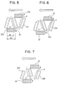
- A rotor (1) of a rotary machine having a plurality of claw poles (18, 20) extending in the axial direction of said rotor (1) alternately from opposite ends of said rotor (1) and a plurality of permanent magnet members (26) held between adjacent two of said claw poles (18, 20), whereineach of said claw poles (18, 20) has tapering trapezoidal outer and inner peripheries and a pair of side surfaces inclined with respect to said axial direction of said rotor (1) to form a rectangular parallelopiped space between one of said side surface of one of said claw poles (18, 20) and an opposite one of said side surface of an adjacent one of said claw poles (18, 20), andeach of said permanent magnet members (26) is fitted to one of said rectangular parallelopiped space, and whereinat least a portion of said permanent magnet members (26) has a side wall extending from said inner periphery of said claw poles (18, 20) over the length of said permanent magnet members (26) to form an axial flow fan.
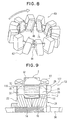
- The rotor (1) as claimed in claim 1 further comprising a cylindrical field coil (12) disposed inside said inner peripheries of said claw poles (18, 20), whereinsaid side walls of said permanent magnet members (26) extend into spaces formed between said inner peripheries of said claw poles (18, 20) and the outer periphery of said field coil (12).
- The rotor (1) as claimed in claim 1 further comprising a shaft (34), a pair of core members (22, 24) each of which has a boss portion (14, 16) fitted to said shaft (34) and a base portion (28, 30) from which said claw poles (18, 20) extend to the other, whereinone opening of said axial flow fan is formed between one end of one of said permanent magnet members (26) and said base portion (28, 30) of one of said core members (22, 24) and the other opening of said axial flow fan is formed between the other end of said one of permanent magnet members (26) and said base portion (28, 30) of the other of said core members (22, 24).
- The rotor (1) as claimed in claim 3, whereina portion (31) of said base portion (28, 30) which forms said opening has a conduit to decrease air flow resistance of said axial flow fan.
- The rotor (1) as claimed in claim 3, whereineach portion of said permanent magnet members (26) which forms said opening has an additional opening to decrease resistance of said air flow generated by said axial flow fan.
- The rotor (1) as claimed in claim 5, whereineach of said permanent magnet members (26) has chamfered portion to form said additional opening.
- The rotor (1) as claimed in claim 1 further comprising a cooling fan (110, 120) fixed to an end thereof.
- The rotor (1) as claimed in claim 6, whereinsaid cooling fan (110, 120) is a centrifugal fan.
- The rotor (1) as claimed in claim 6, whereinsaid axial flow fan formed by said side walls of said permanent magnet members (26) is one-way axial flow fan, andsaid cooling fan (110, 120) is a mixed-flow fan for generating cooling air flow in the same direction as said axial flow fan.
Applications Claiming Priority (3)
| Application Number | Priority Date | Filing Date | Title |
|---|---|---|---|
| JP6801997 | 1997-03-21 | ||
| JP68019/97 | 1997-03-21 | ||
| JP06801997A JP3752770B2 (en) | 1997-03-21 | 1997-03-21 | Landel core type rotary electric machine |
Publications (3)
| Publication Number | Publication Date |
|---|---|
| EP0866542A2 EP0866542A2 (en) | 1998-09-23 |
| EP0866542A3 EP0866542A3 (en) | 1999-09-15 |
| EP0866542B1 true EP0866542B1 (en) | 2002-02-20 |
Family
ID=13361700
Family Applications (1)
| Application Number | Title | Priority Date | Filing Date |
|---|---|---|---|
| EP98104300A Expired - Lifetime EP0866542B1 (en) | 1997-03-21 | 1998-03-10 | Rotor of rotary machine having claw poles and auxiliary permanent magnets |
Country Status (4)
| Country | Link |
|---|---|
| US (1) | US6011343A (en) |
| EP (1) | EP0866542B1 (en) |
| JP (1) | JP3752770B2 (en) |
| DE (1) | DE69803891T2 (en) |
Families Citing this family (35)
| Publication number | Priority date | Publication date | Assignee | Title |
|---|---|---|---|---|
| JPH11127561A (en) * | 1997-10-22 | 1999-05-11 | Denso Corp | Concurrent rotor/magnet for electric rotating machine and manufacture thereof |
| FR2786625B1 (en) * | 1998-11-30 | 2001-02-16 | Valeo Equip Electr Moteur | MOTOR VEHICLE ALTERNATOR WITH INTERPOLAR MAGNETS |
| DE29901126U1 (en) * | 1999-01-23 | 2000-08-10 | Bosch Gmbh Robert | Electrical machine, in particular claw pole generator |
| FR2793085B1 (en) * | 1999-04-30 | 2001-07-13 | Valeo Equip Electr Moteur | ALTERNATOR FOR A MOTOR VEHICLE WITH INTERPOLAR MAGNETS |
| JP3541934B2 (en) * | 2000-01-11 | 2004-07-14 | 三菱電機株式会社 | Alternator rotor |
| DE10005781A1 (en) * | 2000-02-10 | 2001-08-16 | Bosch Gmbh Robert | Alternator for vehicle, includes a stator supporting a stator coil in a casing and a claw pole rotor unit running on bearings on a shaft with two pole collars acting as field spider halves |
| JP4300702B2 (en) * | 2000-10-25 | 2009-07-22 | 株式会社デンソー | AC generator field rotor |
| DE10153578B4 (en) * | 2000-11-06 | 2012-01-26 | Denso Corporation | Alternator for permanent magnet vehicles in the rotor and method of making same |
| WO2002040623A2 (en) * | 2000-11-20 | 2002-05-23 | The Procter & Gamble Company | Fabric softening compositions and methods |
| DE10106519A1 (en) * | 2001-02-13 | 2002-08-22 | Bosch Gmbh Robert | Electrical machine |
| US6690145B2 (en) * | 2002-04-01 | 2004-02-10 | E-Tec Corporation | Permanent magnet alternator and voltage regulator circuit for the permanent magnet alternator |
| JP4048730B2 (en) * | 2001-05-10 | 2008-02-20 | 株式会社デンソー | AC alternator rotor for vehicles |
| US6747384B2 (en) * | 2002-01-24 | 2004-06-08 | Visteon Global Technologies, Inc. | Alternator hybrid magnet rotor design |
| JP3743431B2 (en) * | 2002-04-26 | 2006-02-08 | 株式会社日立製作所 | Vehicle alternator and its rotor |
| US6744165B2 (en) * | 2002-10-29 | 2004-06-01 | Visteon Global Technologies, Inc. | High power permanent magnet hybrid alternator rotor |
| JP3816863B2 (en) * | 2002-11-01 | 2006-08-30 | 三菱電機株式会社 | Rotating electrical machine rotor |
| US20050057106A1 (en) * | 2002-12-10 | 2005-03-17 | Ballard Power Systems Corporation | Methods and systems for electric machines having windings |
| US6707227B1 (en) * | 2002-12-11 | 2004-03-16 | Visteon Global Technologies, Inc. | High power alternator field coil |
| JP3954012B2 (en) | 2003-12-01 | 2007-08-08 | 三菱電機株式会社 | Rotating electrical machine rotor |
| US6933654B1 (en) * | 2004-04-27 | 2005-08-23 | Mitsubishi Denki Kabushiki Kaisha | Rotor of rotating electric machine |
| JP4380652B2 (en) * | 2005-08-26 | 2009-12-09 | 株式会社デンソー | Rotating electric machine rotor |
| JP2007282420A (en) * | 2006-04-10 | 2007-10-25 | Denso Corp | Vehicle ac power generator |
| JP4735980B2 (en) | 2006-08-23 | 2011-07-27 | 株式会社デンソー | AC generator for vehicle and method for manufacturing the same |
| FR2912008B1 (en) * | 2007-01-30 | 2015-04-24 | Valeo Equip Electr Moteur | ROTOR OF ROTATING ELECTRIC MACHINE EQUIPPED WITH AT LEAST ONE MEMBER FORMING A MAGNETIC BARRIER CARRIED BY A SUPPORT COMPRISING A VENTILATION OR NOISE REDUCTION ELEMENT |
| DE102007032140A1 (en) * | 2007-06-30 | 2009-01-02 | Robert Bosch Gmbh | Electric machine |
| JP2009077588A (en) * | 2007-09-21 | 2009-04-09 | Denso Corp | Ac generator for vehicle |
| JP2009183042A (en) * | 2008-01-30 | 2009-08-13 | Denso Corp | Alternator for vehicles |
| US8334633B2 (en) | 2008-04-04 | 2012-12-18 | Mitsubishi Electric Corporation | Dynamoelectric machine |
| US8629597B2 (en) * | 2010-03-03 | 2014-01-14 | Remy Technologies, Llc | Airflow passage arrangement for claw-pole electric machines |
| JP6071778B2 (en) * | 2013-06-27 | 2017-02-01 | 株式会社東芝 | Electric motors for vehicles and railway vehicles |
| JP6464584B2 (en) * | 2014-07-10 | 2019-02-06 | 富士電機株式会社 | Permanent magnet synchronous motor rotor, permanent magnet synchronous motor and permanent magnet synchronous motor device |
| JP7002568B2 (en) * | 2018-01-18 | 2022-01-20 | 三菱電機株式会社 | Rotor of rotary electric machine for vehicles and its manufacturing method |
| DE102019100907A1 (en) * | 2019-01-15 | 2020-07-16 | Gkn Sinter Metals Engineering Gmbh | Electric motor |
| CN112128041A (en) * | 2020-09-07 | 2020-12-25 | 金华市捷欣智能科技有限公司 | Miniature water flow generator |
| DE102022201537A1 (en) | 2022-02-15 | 2023-08-17 | Siemens Mobility GmbH | Electric machine with hybrid excitation |
Family Cites Families (12)
| Publication number | Priority date | Publication date | Assignee | Title |
|---|---|---|---|---|
| US3271606A (en) * | 1962-11-05 | 1966-09-06 | Gen Motors Corp | Rotor assembly |
| DE1209651B (en) * | 1964-04-28 | 1966-01-27 | Bosch Gmbh Robert | Self-exciting alternator |
| JP3131979B2 (en) * | 1990-06-19 | 2001-02-05 | 株式会社デンソー | Claw pole type field core and manufacturing method thereof |
| JP3237217B2 (en) * | 1991-08-08 | 2001-12-10 | 株式会社デンソー | Vehicle alternator rotor |
| JP2875706B2 (en) * | 1993-03-25 | 1999-03-31 | 三菱電機株式会社 | AC generator for vehicles |
| JP2548882B2 (en) * | 1993-05-07 | 1996-10-30 | 日本電装株式会社 | Vehicle alternator |
| JP3419080B2 (en) * | 1993-07-26 | 2003-06-23 | 株式会社デンソー | Rotating electric machine |
| JP3446313B2 (en) * | 1993-08-30 | 2003-09-16 | 株式会社デンソー | Rotating electric machine rotor |
| US5578885A (en) * | 1994-12-22 | 1996-11-26 | General Motors Corporation | Rotor assembly for hybrid alternator |
| JP2674556B2 (en) * | 1995-04-12 | 1997-11-12 | 株式会社デンソー | Vehicle alternator |
| JP3709582B2 (en) * | 1995-08-11 | 2005-10-26 | 株式会社デンソー | Vehicle alternator |
| JPH09163700A (en) * | 1995-12-08 | 1997-06-20 | Mitsubishi Electric Corp | Ac generator |
-
1997
- 1997-03-21 JP JP06801997A patent/JP3752770B2/en not_active Expired - Fee Related
-
1998
- 1998-03-10 US US09/037,498 patent/US6011343A/en not_active Expired - Lifetime
- 1998-03-10 DE DE69803891T patent/DE69803891T2/en not_active Expired - Lifetime
- 1998-03-10 EP EP98104300A patent/EP0866542B1/en not_active Expired - Lifetime
Also Published As
| Publication number | Publication date |
|---|---|
| DE69803891D1 (en) | 2002-03-28 |
| US6011343A (en) | 2000-01-04 |
| EP0866542A2 (en) | 1998-09-23 |
| JPH10271780A (en) | 1998-10-09 |
| EP0866542A3 (en) | 1999-09-15 |
| JP3752770B2 (en) | 2006-03-08 |
| DE69803891T2 (en) | 2002-10-10 |
Similar Documents
| Publication | Publication Date | Title |
|---|---|---|
| EP0866542B1 (en) | Rotor of rotary machine having claw poles and auxiliary permanent magnets | |
| CN101154836B (en) | Rotating electrical machine and alternating-current generator | |
| EP0977342B1 (en) | Ac generator having claw-pole rotor | |
| EP1050949A1 (en) | Motor | |
| US6995493B2 (en) | Rotor of rotating electric machine | |
| CN110247497B (en) | Rotor of rotating electric machine | |
| KR20160066841A (en) | Rotor structure of wrsm motor | |
| US6936945B2 (en) | Permanent magnet synchronous motor | |
| JP6615375B2 (en) | Electric motor and air conditioner | |
| KR20110058057A (en) | Permanent magnet type motor | |
| EP0905868B1 (en) | A low armature reaction magnetic circuit structure for a DC electric machine | |
| JP5211914B2 (en) | Rotating electric machine for vehicles | |
| JP4368546B2 (en) | Thin flat multiphase induction rotating machine for vehicles | |
| KR20220117051A (en) | Stator heat radiating structure of vehicle alternator | |
| CN112994287A (en) | Rotating electrical machine | |
| JPH0127406Y2 (en) | ||
| GB2565450A (en) | Rotor, electric motor, compressor, fan, and air conditioner | |
| JP2865094B2 (en) | AC generator | |
| JP3656347B2 (en) | Rotating machine rotor | |
| TWI807730B (en) | Motors, air supply units and refrigeration units | |
| JP7204018B2 (en) | Rotors, electric motors, blowers and air conditioners | |
| JP2020129880A (en) | Electric motor, electric blower using the same, and electric vacuum cleaner using the same | |
| CN116961291A (en) | Stator punching structure, high-speed motor stator and high-speed motor | |
| JP2001128429A (en) | Magnet-type generator | |
| JPS59136042A (en) | Flat rotary electric machine |
Legal Events
| Date | Code | Title | Description |
|---|---|---|---|
| PUAI | Public reference made under article 153(3) epc to a published international application that has entered the european phase |
Free format text: ORIGINAL CODE: 0009012 |
|
| AK | Designated contracting states |
Kind code of ref document: A2 Designated state(s): DE FR GB |
|
| AX | Request for extension of the european patent |
Free format text: AL;LT;LV;MK;RO;SI |
|
| PUAL | Search report despatched |
Free format text: ORIGINAL CODE: 0009013 |
|
| AK | Designated contracting states |
Kind code of ref document: A3 Designated state(s): AT BE CH DE DK ES FI FR GB GR IE IT LI LU MC NL PT SE |
|
| AX | Request for extension of the european patent |
Free format text: AL;LT;LV;MK;RO;SI |
|
| 17P | Request for examination filed |
Effective date: 19990831 |
|
| AKX | Designation fees paid |
Free format text: DE FR GB |
|
| GRAG | Despatch of communication of intention to grant |
Free format text: ORIGINAL CODE: EPIDOS AGRA |
|
| 17Q | First examination report despatched |
Effective date: 20010418 |
|
| GRAG | Despatch of communication of intention to grant |
Free format text: ORIGINAL CODE: EPIDOS AGRA |
|
| GRAH | Despatch of communication of intention to grant a patent |
Free format text: ORIGINAL CODE: EPIDOS IGRA |
|
| GRAH | Despatch of communication of intention to grant a patent |
Free format text: ORIGINAL CODE: EPIDOS IGRA |
|
| REG | Reference to a national code |
Ref country code: GB Ref legal event code: IF02 |
|
| GRAA | (expected) grant |
Free format text: ORIGINAL CODE: 0009210 |
|
| AK | Designated contracting states |
Kind code of ref document: B1 Designated state(s): DE FR GB |
|
| REF | Corresponds to: |
Ref document number: 69803891 Country of ref document: DE Date of ref document: 20020328 |
|
| ET | Fr: translation filed | ||
| REG | Reference to a national code |
Ref country code: GB Ref legal event code: 746 Effective date: 20021128 |
|
| PLBE | No opposition filed within time limit |
Free format text: ORIGINAL CODE: 0009261 |
|
| STAA | Information on the status of an ep patent application or granted ep patent |
Free format text: STATUS: NO OPPOSITION FILED WITHIN TIME LIMIT |
|
| 26N | No opposition filed |
Effective date: 20021121 |
|
| PGFP | Annual fee paid to national office [announced via postgrant information from national office to epo] |
Ref country code: FR Payment date: 20110317 Year of fee payment: 14 |
|
| PGFP | Annual fee paid to national office [announced via postgrant information from national office to epo] |
Ref country code: GB Payment date: 20110309 Year of fee payment: 14 |
|
| GBPC | Gb: european patent ceased through non-payment of renewal fee |
Effective date: 20120310 |
|
| REG | Reference to a national code |
Ref country code: FR Ref legal event code: ST Effective date: 20121130 |
|
| PG25 | Lapsed in a contracting state [announced via postgrant information from national office to epo] |
Ref country code: GB Free format text: LAPSE BECAUSE OF NON-PAYMENT OF DUE FEES Effective date: 20120310 Ref country code: FR Free format text: LAPSE BECAUSE OF NON-PAYMENT OF DUE FEES Effective date: 20120402 |
|
| PGFP | Annual fee paid to national office [announced via postgrant information from national office to epo] |
Ref country code: DE Payment date: 20170322 Year of fee payment: 20 |
|
| REG | Reference to a national code |
Ref country code: DE Ref legal event code: R071 Ref document number: 69803891 Country of ref document: DE |