EP0866232B1 - Center bearing assembly with rheological fluid for damping vibrations - Google Patents
Center bearing assembly with rheological fluid for damping vibrations Download PDFInfo
- Publication number
- EP0866232B1 EP0866232B1 EP98105134A EP98105134A EP0866232B1 EP 0866232 B1 EP0866232 B1 EP 0866232B1 EP 98105134 A EP98105134 A EP 98105134A EP 98105134 A EP98105134 A EP 98105134A EP 0866232 B1 EP0866232 B1 EP 0866232B1
- Authority
- EP
- European Patent Office
- Prior art keywords
- fluid
- damper
- radially
- roller bearing
- blades
- Prior art date
- Legal status (The legal status is an assumption and is not a legal conclusion. Google has not performed a legal analysis and makes no representation as to the accuracy of the status listed.)
- Expired - Lifetime
Links
Images

Classifications
-
- F—MECHANICAL ENGINEERING; LIGHTING; HEATING; WEAPONS; BLASTING
- F16—ENGINEERING ELEMENTS AND UNITS; GENERAL MEASURES FOR PRODUCING AND MAINTAINING EFFECTIVE FUNCTIONING OF MACHINES OR INSTALLATIONS; THERMAL INSULATION IN GENERAL
- F16C—SHAFTS; FLEXIBLE SHAFTS; ELEMENTS OR CRANKSHAFT MECHANISMS; ROTARY BODIES OTHER THAN GEARING ELEMENTS; BEARINGS
- F16C27/00—Elastic or yielding bearings or bearing supports, for exclusively rotary movement
- F16C27/06—Elastic or yielding bearings or bearing supports, for exclusively rotary movement by means of parts of rubber or like materials
- F16C27/066—Ball or roller bearings
-
- B—PERFORMING OPERATIONS; TRANSPORTING
- B60—VEHICLES IN GENERAL
- B60K—ARRANGEMENT OR MOUNTING OF PROPULSION UNITS OR OF TRANSMISSIONS IN VEHICLES; ARRANGEMENT OR MOUNTING OF PLURAL DIVERSE PRIME-MOVERS IN VEHICLES; AUXILIARY DRIVES FOR VEHICLES; INSTRUMENTATION OR DASHBOARDS FOR VEHICLES; ARRANGEMENTS IN CONNECTION WITH COOLING, AIR INTAKE, GAS EXHAUST OR FUEL SUPPLY OF PROPULSION UNITS IN VEHICLES
- B60K17/00—Arrangement or mounting of transmissions in vehicles
- B60K17/22—Arrangement or mounting of transmissions in vehicles characterised by arrangement, location, or type of main drive shafting, e.g. cardan shaft
- B60K17/24—Arrangement of mountings for shafting
-
- F—MECHANICAL ENGINEERING; LIGHTING; HEATING; WEAPONS; BLASTING
- F16—ENGINEERING ELEMENTS AND UNITS; GENERAL MEASURES FOR PRODUCING AND MAINTAINING EFFECTIVE FUNCTIONING OF MACHINES OR INSTALLATIONS; THERMAL INSULATION IN GENERAL
- F16C—SHAFTS; FLEXIBLE SHAFTS; ELEMENTS OR CRANKSHAFT MECHANISMS; ROTARY BODIES OTHER THAN GEARING ELEMENTS; BEARINGS
- F16C27/00—Elastic or yielding bearings or bearing supports, for exclusively rotary movement
- F16C27/04—Ball or roller bearings, e.g. with resilient rolling bodies
-
- F—MECHANICAL ENGINEERING; LIGHTING; HEATING; WEAPONS; BLASTING
- F16—ENGINEERING ELEMENTS AND UNITS; GENERAL MEASURES FOR PRODUCING AND MAINTAINING EFFECTIVE FUNCTIONING OF MACHINES OR INSTALLATIONS; THERMAL INSULATION IN GENERAL
- F16F—SPRINGS; SHOCK-ABSORBERS; MEANS FOR DAMPING VIBRATION
- F16F15/00—Suppression of vibrations in systems; Means or arrangements for avoiding or reducing out-of-balance forces, e.g. due to motion
- F16F15/10—Suppression of vibrations in rotating systems by making use of members moving with the system
- F16F15/18—Suppression of vibrations in rotating systems by making use of members moving with the system using electric, magnetic or electromagnetic means
-
- F—MECHANICAL ENGINEERING; LIGHTING; HEATING; WEAPONS; BLASTING
- F16—ENGINEERING ELEMENTS AND UNITS; GENERAL MEASURES FOR PRODUCING AND MAINTAINING EFFECTIVE FUNCTIONING OF MACHINES OR INSTALLATIONS; THERMAL INSULATION IN GENERAL
- F16F—SPRINGS; SHOCK-ABSORBERS; MEANS FOR DAMPING VIBRATION
- F16F9/00—Springs, vibration-dampers, shock-absorbers, or similarly-constructed movement-dampers using a fluid or the equivalent as damping medium
- F16F9/32—Details
- F16F9/53—Means for adjusting damping characteristics by varying fluid viscosity, e.g. electromagnetically
- F16F9/535—Magnetorheological [MR] fluid dampers
Definitions
- the present invention relates to a to a damper apparatus for damping vibrations in a roller bearing.
- a center bearing assembly supports a section of a vehicle drive shaft on the vehicle frame.
- the center bearing assembly includes a roller bearing which directly engages and supports the section of the drive shaft for rotation.
- the center bearing assembly further includes a housing which contains and supports the roller bearing on the vehicle frame.
- the center bearing assembly further includes a damper apparatus for damping vibrations radially between the roller bearing and the housing.
- US-A-5 452 957 discloses a prior art in accordance with the preamble of claim 1.
- This prior art document shows in particular a center bearing assembly including a roller bearing adapted to receive and rotatably support a coupling shaft and a bracket adapted to be secured to a vehicle frame.
- a support member is provided which supports the roller bearing within the bracket.
- the support member includes a bladder formed of an elastomeric material.
- the bladder contains a rheological fluid which exhibits a significant change in its ability to flow or shear upon the application of an appropriate energy field.
- the bladder contains a magneto -rheological magnetic fluid.
- the apparatus 10 includes a vehicle drive shaft 12 and a center bearing assembly 14.
- the center bearing assembly 14 includes a roller bearing 16 which supports the drive shaft 12 for rotation.
- the center bearing assembly 14 further includes an annular housing 18 which contains and supports the roller bearing 16 on a vehicle frame.
- a damper assembly 20 also is contained within the housing 18. The damper assembly 20 damps vibrations radially between the roller bearing 16 and the housing 18.
- the drive shaft 12 has a plurality of interconnected sections which rotate together to transmit torque from a vehicle transmission to a differential gear at a driven rear axle of the vehicle.
- the sections of the drive shaft 12 include a midship tube 22 and a center shaft 24.
- the midship tube 22 is fixed to an enlarged forward end portion 26 of the center shaft 24.
- a yoke 28 in a universal joint 30 (shown partially) is fixed to a rear end portion of the center shaft 24.
- the universal joint 30 rotatably joins the center shaft 24 with another section (not shown) of the drive shaft 12 in a known manner.
- any suitable fastening structures known in the art such as welds, splines, pins, or the like, can be used to interconnect the midship tube 22, the center shaft 24, and the yoke 28, as well as other interconnected parts of the apparatus 10 described below.
- Such fastening structures are omitted from the drawings for clarity of illustration.
- the roller bearing 16 has a plurality of rollers 32 between an inner race 34 and an outer race 36.
- the inner race 34 is fixed to the center shaft 24 between the enlarged end portion 26 and a cylindrical spacer tube 38.
- the spacer tube 38 extends axially over the center shaft 24 from the inner race 34 to the yoke 28.
- the outer race 36 is closely received within, and is fixed to, a crimped tubular wall portion 40 of the center bearing assembly 14. The center shaft 24 and the inner race 34 are thus rotatable together about an axis 41 relative to the outer race 36 and the surrounding center bearing assembly 14.
- a rear wall 50 of the housing 18 is shaped as a cylindrical tube extending circumferentially entirely around the axis 41.
- a forward wall 52 of the housing 18 has a channel-shaped cross section, and extends only partially around the axis 41.
- an upper portion 54 of the forward housing wall 52 extends circumferentially around the upper half of the center bearing assembly 14 in the shape of a semi-circular arc.
- a pair of parallel arm portions 56 of the forward housing wall 52 project tangentially downward on opposite sides of the lower half of the center bearing assembly 14.
- a corresponding pair of mounting portions 58 project oppositely outward (in directions perpendicular to the page as viewed in Fig. 1) from the lower ends of the arm portions 56.
- the mounting portions 58 of the forward housing wall 52 are used to mount the center bearing assembly 14 on a vehicle frame in a known manner.
- a pair of concentric rings 60 and a rubber seal 62 close the forward end of the center bearing assembly 14 radially outward of the crimped tubular wall 40.
- the damper assembly 20 comprises a plurality of annular parts located radially between the center shaft 24 and the housing 18. These include a sleeve 70 and an inner ring 72.
- the sleeve 70 is a relatively thin cylindrical part which is press fitted into the inner ring 72.
- the inner ring 72 has a somewhat conical configuration which is stepped radially outward, and extends closely into the crimped tubular wall 40.
- a weld or, as noted above, any other suitable fastening structure fixes the inner ring 72 to the crimped tubular wall 40.
- the sleeve 70 and the inner ring 72 are fixed to the outer bearing race 36 so as to vibrate radially with the outer bearing race 36.
- a pair of damper blades 80 and 82 project radially outward from the sleeve 70 at locations that are spaced a short distance from one another.
- the first damper blade 80 is a flat circular ring.
- the first damper blade 80 thus has a radially outer free edge surface 86 (Fig. 2) and a pair of planar opposite side surfaces 88.
- the second damper blade 82 also is a flat circular ring with a radially outer free edge surface 92 and a pair of planar opposite side surfaces 94.
- a corresponding pair of fastening structures fixes the first and second damper rings 80 and 82 to the sleeve 70. Accordingly, the first and second damper rings 80 and 82 also are fixed to the outer bearing race 36 so as to vibrate radially with the outer bearing race 36.
- annular parts of the damper assembly 20 are not fixed to the outer bearing race 36. As shown in Fig. 1, such parts include a pair of support rings 100 and 102, a third damper blade 104, and an electromagnetic field assembly 106. Those parts 100-106 are supported for vibrational movement radially relative to the sleeve 70, the ring 72, and the outer bearing race 36.
- the first support ring 100 has an L-shaped cross section defined by a cylindrical side wall 110 and a ringshaped end wall 112.
- the side wall 110 and a surrounding plastic bushing 114 are press fitted together within the rear housing wall 50.
- the end wall 112 projects radially inward from the side wall 110, and can slide radially against an adjacent portion 115 of the inner ring 72.
- a radially inner edge portion 116 (Fig. 2) of the end wall 112 compressively holds a closed-cell foam insert 118 in a groove 120 in the inner ring 72.
- the second support ring 102 has a generally T-shaped cross section defined by a rim portion 122 and a flange portion 124.
- the third damper blade 104 which also is a flat circular ring, is fixed to the flange portion 124 of the second support ring 102 (preferably by a weld), and projects radially inward from the flange portion 124 between the first and second damper blades 80 and 82.
- the third damper blade 104 has a radially inner free edge surface 130 and pair of planar opposite side surfaces 132. The opposite side surfaces 132 of the third damper blade 104 are spaced axially from the adjacent side surfaces 88 and 94 of the first and second damper blades 80 and 82.
- the third damper blade 104 is fixed to the support rings 100 and 102, it is likewise movable radially to the inner ring 72 and the sleeve 70.
- the third damper blade 104 is thus movable radially relative to the first and second damper blades 80 and 82 upon radial vibration of the outer bearing race 36.
- the electromagnetic field assembly 106 is screwed into the first retainer ring 100 at the cylindrical side wall 110 of the first retainer ring 100.
- a coil 140 (shown schematically) in the electromagnetic field assembly 106 extends circumferentially around the axis 41.
- Another closed-cell foam insert 142 overlies the coil 140.
- the damper assembly 20 defines a closed fluid chamber 150 which is filled with rheological fluid 152.
- the fluid 152 is a magnetic field responsive fluid and may have any suitable composition known in the art.
- the chamber 150 has an annular shape extending circumferentially around the axis 41. As best shown in enlarged detail in Fig. 2, the chamber 150 extends axially between the electromagnetic field assembly 106 and the end wall 112 of the first support ring 100. The chamber 150 further extends radially between the sleeve 70 and the rim portion 122 of the second support ring 102.
- the damper blades 80, 82 and 104 thus project radially into the fluid 152 in the chamber 150.
- the foam inserts 118 and 142 and a pair of O-rings 154 and 156 block the fluid 152 from leaking outward from the chamber 150.
- the coil 140 is operatively connected with a controller 160 and a sensor 162.
- the controller 160 responds to the sensor 162 by energizing the coil 140, i.e., by directing electric current through the coil 140, in an amount correlated to a vehicle operating condition that is sensed and indicated by the sensor 162.
- the vehicle operating condition is the speed of the rotating drive shaft 12.
- the controller 160 directs electric current through the coil 140 and varies the current inversely relative to variations in the shaft speed.
- the resulting magnetic field has lines of flux that extend from the electromagnetic field assembly 106 (Fig. 1) through the rheological fluid 152 in the chamber 150.
- the damper blades 80, 82 and 104 are formed of magnetic material, such as 1008 steel or soft iron, so as not to block the lines of magnetic flux from extending fully through the fluid 152 between their opposed side surfaces 88, 130 and 94.
- the controller 160 varies the current in the coil 140 in response to variations in the speed of the rotating drive shaft 12, the intensity of the magnetic field acting upon the fluid 152 in the chamber 150 varies accordingly. This causes the resistance to shear of the fluid 152 to vary in corresponding amounts. The fluid 152 thus resists movement of the damper blades 80, 82 and 104 radially relative to each other in the chamber 150 so as to damp radial vibrations of the outer bearing race 36 in an amount correlated to the speed of the rotating drive shaft 12.
Landscapes
- Engineering & Computer Science (AREA)
- General Engineering & Computer Science (AREA)
- Mechanical Engineering (AREA)
- Physics & Mathematics (AREA)
- Electromagnetism (AREA)
- Aviation & Aerospace Engineering (AREA)
- Acoustics & Sound (AREA)
- Chemical & Material Sciences (AREA)
- Combustion & Propulsion (AREA)
- Transportation (AREA)
- Support Of The Bearing (AREA)
- Vibration Prevention Devices (AREA)
- Arrangement Or Mounting Of Propulsion Units For Vehicles (AREA)
- Rolling Contact Bearings (AREA)
Description
- The present invention relates to a to a damper apparatus for damping vibrations in a roller bearing.
- A center bearing assembly supports a section of a vehicle drive shaft on the vehicle frame. The center bearing assembly includes a roller bearing which directly engages and supports the section of the drive shaft for rotation. The center bearing assembly further includes a housing which contains and supports the roller bearing on the vehicle frame.
- When the drive shaft rotates, vibrations are transmitted radially through the center bearing assembly from the drive shaft to the vehicle frame. Therefore, the center bearing assembly further includes a damper apparatus for damping vibrations radially between the roller bearing and the housing.
- Further attention is drawn to US-A-5 452 957, which discloses a prior art in accordance with the preamble of claim 1. This prior art document shows in particular a center bearing assembly including a roller bearing adapted to receive and rotatably support a coupling shaft and a bracket adapted to be secured to a vehicle frame. A support member is provided which supports the roller bearing within the bracket. The support member includes a bladder formed of an elastomeric material. The bladder contains a rheological fluid which exhibits a significant change in its ability to flow or shear upon the application of an appropriate energy field. Preferably, the bladder contains a magneto -rheological magnetic fluid. By varying the power supplied to an electromagnet located adjacent the bladder, the vibration dampening characteristics of the support member may be varied depending upon the operating conditions of the vehicle.
- In accordance with the present invention an apparatus comprising a roller bearing and a damper assembly, as set forth in claim 1, is provided. Preferred embodiments of the present invention are claimed in the dependent claims.
- The foregoing and other features of the present invention will become apparent to one skilled in the art to which the present invention relates upon consideration of the following description of the invention with reference to the accompanying drawings, wherein:
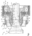
- Fig. 1 is a view of an apparatus comprising a preferred embodiment of the present invention;
- Fig. 2 is an enlarged partial view of parts shown in Fig. 1; and
- Fig. 3 is a schematic view showing other parts of the apparatus.
-
- An
apparatus 10 comprising a preferred embodiment of the present invention is shown in Fig. 1. Theapparatus 10 includes avehicle drive shaft 12 and acenter bearing assembly 14. Thecenter bearing assembly 14 includes a roller bearing 16 which supports thedrive shaft 12 for rotation. Thecenter bearing assembly 14 further includes anannular housing 18 which contains and supports the roller bearing 16 on a vehicle frame. Adamper assembly 20 also is contained within thehousing 18. Thedamper assembly 20 damps vibrations radially between the roller bearing 16 and thehousing 18. - The
drive shaft 12 has a plurality of interconnected sections which rotate together to transmit torque from a vehicle transmission to a differential gear at a driven rear axle of the vehicle. As shown partially in Fig. 1, the sections of thedrive shaft 12 include amidship tube 22 and acenter shaft 24. Themidship tube 22 is fixed to an enlargedforward end portion 26 of thecenter shaft 24. Ayoke 28 in a universal joint 30 (shown partially) is fixed to a rear end portion of thecenter shaft 24. Theuniversal joint 30 rotatably joins thecenter shaft 24 with another section (not shown) of thedrive shaft 12 in a known manner. Any suitable fastening structures known in the art, such as welds, splines, pins, or the like, can be used to interconnect themidship tube 22, thecenter shaft 24, and theyoke 28, as well as other interconnected parts of theapparatus 10 described below. Such fastening structures are omitted from the drawings for clarity of illustration. - The roller bearing 16 has a plurality of
rollers 32 between aninner race 34 and anouter race 36. Theinner race 34 is fixed to thecenter shaft 24 between the enlargedend portion 26 and acylindrical spacer tube 38. Thespacer tube 38 extends axially over thecenter shaft 24 from theinner race 34 to theyoke 28. Theouter race 36 is closely received within, and is fixed to, a crimpedtubular wall portion 40 of thecenter bearing assembly 14. Thecenter shaft 24 and theinner race 34 are thus rotatable together about anaxis 41 relative to theouter race 36 and the surroundingcenter bearing assembly 14. - A
rear wall 50 of thehousing 18 is shaped as a cylindrical tube extending circumferentially entirely around theaxis 41. Aforward wall 52 of thehousing 18 has a channel-shaped cross section, and extends only partially around theaxis 41. Specifically, anupper portion 54 of theforward housing wall 52 extends circumferentially around the upper half of thecenter bearing assembly 14 in the shape of a semi-circular arc. A pair ofparallel arm portions 56 of theforward housing wall 52, one of which is shown in the sectional view of Fig. 1, project tangentially downward on opposite sides of the lower half of thecenter bearing assembly 14. A corresponding pair ofmounting portions 58 project oppositely outward (in directions perpendicular to the page as viewed in Fig. 1) from the lower ends of thearm portions 56. The mountingportions 58 of theforward housing wall 52 are used to mount thecenter bearing assembly 14 on a vehicle frame in a known manner. A pair ofconcentric rings 60 and arubber seal 62 close the forward end of thecenter bearing assembly 14 radially outward of the crimpedtubular wall 40. - The
damper assembly 20 comprises a plurality of annular parts located radially between thecenter shaft 24 and thehousing 18. These include asleeve 70 and aninner ring 72. Thesleeve 70 is a relatively thin cylindrical part which is press fitted into theinner ring 72. Theinner ring 72 has a somewhat conical configuration which is stepped radially outward, and extends closely into the crimpedtubular wall 40. A weld or, as noted above, any other suitable fastening structure fixes theinner ring 72 to the crimpedtubular wall 40. In this arrangement, thesleeve 70 and theinner ring 72 are fixed to theouter bearing race 36 so as to vibrate radially with theouter bearing race 36. - A pair of
damper blades sleeve 70 at locations that are spaced a short distance from one another. Thefirst damper blade 80 is a flat circular ring. Thefirst damper blade 80 thus has a radially outer free edge surface 86 (Fig. 2) and a pair of planaropposite side surfaces 88. Thesecond damper blade 82 also is a flat circular ring with a radially outerfree edge surface 92 and a pair of planaropposite side surfaces 94. A corresponding pair of fastening structures (preferably welds) fixes the first andsecond damper rings sleeve 70. Accordingly, the first andsecond damper rings outer bearing race 36 so as to vibrate radially with theouter bearing race 36. - Several of the annular parts of the
damper assembly 20 are not fixed to theouter bearing race 36. As shown in Fig. 1, such parts include a pair ofsupport rings third damper blade 104, and anelectromagnetic field assembly 106. Those parts 100-106 are supported for vibrational movement radially relative to thesleeve 70, thering 72, and theouter bearing race 36. - The
first support ring 100 has an L-shaped cross section defined by acylindrical side wall 110 and aringshaped end wall 112. Theside wall 110 and a surroundingplastic bushing 114 are press fitted together within therear housing wall 50. Theend wall 112 projects radially inward from theside wall 110, and can slide radially against anadjacent portion 115 of theinner ring 72. A radially inner edge portion 116 (Fig. 2) of theend wall 112 compressively holds a closed-cell foam insert 118 in agroove 120 in theinner ring 72. - As further shown in Fig. 2, the
second support ring 102 has a generally T-shaped cross section defined by arim portion 122 and aflange portion 124. Thethird damper blade 104, which also is a flat circular ring, is fixed to theflange portion 124 of the second support ring 102 (preferably by a weld), and projects radially inward from theflange portion 124 between the first andsecond damper blades third damper blade 104 has a radially innerfree edge surface 130 and pair of planar opposite side surfaces 132. The opposite side surfaces 132 of thethird damper blade 104 are spaced axially from the adjacent side surfaces 88 and 94 of the first andsecond damper blades third damper blade 104 is fixed to the support rings 100 and 102, it is likewise movable radially to theinner ring 72 and thesleeve 70. Thethird damper blade 104 is thus movable radially relative to the first andsecond damper blades outer bearing race 36. - The
electromagnetic field assembly 106 is screwed into thefirst retainer ring 100 at thecylindrical side wall 110 of thefirst retainer ring 100. A coil 140 (shown schematically) in theelectromagnetic field assembly 106 extends circumferentially around theaxis 41. Another closed-cell foam insert 142 overlies thecoil 140. - The
damper assembly 20 defines a closed fluid chamber 150 which is filled withrheological fluid 152. In the preferred embodiment of the present invention, the fluid 152 is a magnetic field responsive fluid and may have any suitable composition known in the art. The chamber 150 has an annular shape extending circumferentially around theaxis 41. As best shown in enlarged detail in Fig. 2, the chamber 150 extends axially between theelectromagnetic field assembly 106 and theend wall 112 of thefirst support ring 100. The chamber 150 further extends radially between thesleeve 70 and therim portion 122 of thesecond support ring 102. Thedamper blades rings - As shown schematically in Fig. 3, the
coil 140 is operatively connected with acontroller 160 and asensor 162. Thecontroller 160 responds to thesensor 162 by energizing thecoil 140, i.e., by directing electric current through thecoil 140, in an amount correlated to a vehicle operating condition that is sensed and indicated by thesensor 162. In the preferred embodiment of the present invention, the vehicle operating condition is the speed of therotating drive shaft 12. When the speed of therotating drive shaft 12 is within a predetermined range of relatively low speeds, thecontroller 160 directs electric current through thecoil 140 and varies the current inversely relative to variations in the shaft speed. The resulting magnetic field has lines of flux that extend from the electromagnetic field assembly 106 (Fig. 1) through therheological fluid 152 in the chamber 150. In accordance with this feature of the present invention, thedamper blades - When the
controller 160 varies the current in thecoil 140 in response to variations in the speed of therotating drive shaft 12, the intensity of the magnetic field acting upon the fluid 152 in the chamber 150 varies accordingly. This causes the resistance to shear of the fluid 152 to vary in corresponding amounts. The fluid 152 thus resists movement of thedamper blades outer bearing race 36 in an amount correlated to the speed of therotating drive shaft 12. - From the above description of the invention, those skilled in the art will perceive improvements, changes and modifications. Such improvements, changes and modifications within the skill of the art are intended to be covered by the appended claims.
Claims (9)
- Apparatus (10) comprising:said damper assembly (20) further includes a damper blade (80, 82, 104) projecting radially into said fluid (152) from one toward the other of said annular parts, said damper blade (80, 82, 104) being radially movable within said fluid (152) in response to said radial vibrations of said outer race (36).a roller bearing (16) including an inner race (34) rotatable within an outer race (36); anda damper assembly (20) defining a closed chamber (150) containing rheological fluid (152), characterised in that said damper assembly (20) includes a pair of annular parts which are radially movable relative to one another in response to radial vibrations of said outer race (36);
- Apparatus as defined in claim 1 further comprising:a vehicle drive shaft (12); wherein said
roller bearing (16) supports said drive shaft (12) for rotation;a housing (18) which contains and supports said roller bearing (16) in a vehicle; wherein said
damper assembly (20) which damps vibrations radially between said roller bearing (16) and said housing (18); and wherein
said damper blades (80, 82, 104) form a flow-inducing part projecting into said fluid. - Apparatus (10) as defined in claim 1 or 2 wherein said fluid (152) is a magnetic field responsive fluid, said damper blade (80, 82, 104) being formed of magnetic material.
- Apparatus as defined in claim 1 or 2 wherein said damper blade (80,82) and said one of said annular parts (70) are fixed to said outer race (36).
- Apparatus (10) as defined in claim 1 or 2 wherein said damper blade (80, 82, 104) comprises a circular ring with planar opposite side surfaces and a free edge surface movable within said fluid.
- Apparatus (10) as defined in claim 1 or 2 wherein said damper blade (80, 82, 104) is one of a plurality of damper blades (80, 82, 104) projecting radially into said fluid (152), each of said damper blades comprises a circular ring with planar opposite side surfaces and a free edge surface movable within said fluid.
- Apparatus (10) as defined in claim 6 wherein said damper blades (80, 82, 104) comprise a pair (80, 82) of axially adjacent damper blades projecting oppositely from said annular parts of said damper structure.
- Apparatus (10) as defined in claim 7 wherein said adjacent damper blades (80, 82) are spaced apart axially across a fluid flow space within said chamber (150).
- Apparatus (10) as defined in claim 8 wherein said fluid (152) is a magnetic field responsive fluid, said apparatus (10) further comprising an electric coil (140) which, when energized, generates a magnetic field which acts upon said fluid (152).
Applications Claiming Priority (2)
| Application Number | Priority Date | Filing Date | Title |
|---|---|---|---|
| US08/823,291 US5730531A (en) | 1997-03-21 | 1997-03-21 | Center bearing assembly with rheological fluid for damping vibrations |
| US823291 | 1997-03-21 |
Publications (3)
| Publication Number | Publication Date |
|---|---|
| EP0866232A2 EP0866232A2 (en) | 1998-09-23 |
| EP0866232A3 EP0866232A3 (en) | 2000-01-12 |
| EP0866232B1 true EP0866232B1 (en) | 2004-10-27 |
Family
ID=25238334
Family Applications (1)
| Application Number | Title | Priority Date | Filing Date |
|---|---|---|---|
| EP98105134A Expired - Lifetime EP0866232B1 (en) | 1997-03-21 | 1998-03-20 | Center bearing assembly with rheological fluid for damping vibrations |
Country Status (5)
| Country | Link |
|---|---|
| US (1) | US5730531A (en) |
| EP (1) | EP0866232B1 (en) |
| CA (1) | CA2233106C (en) |
| DE (1) | DE69827180T2 (en) |
| ES (1) | ES2231912T3 (en) |
Families Citing this family (24)
| Publication number | Priority date | Publication date | Assignee | Title |
|---|---|---|---|---|
| US5902048A (en) * | 1997-12-19 | 1999-05-11 | Dana Corporation | Center bearing assembly having shear plate |
| US6017168A (en) * | 1997-12-22 | 2000-01-25 | Abb Vetco Gray Inc. | Fluid assist bearing for telescopic joint of a RISER system |
| US6019392A (en) * | 1998-11-18 | 2000-02-01 | Takata, Inc. | Variable level seatbelt energy management device |
| US6116784A (en) * | 1999-01-07 | 2000-09-12 | Brotz; Gregory R. | Dampenable bearing |
| AU2001271797A1 (en) * | 2000-07-03 | 2002-01-14 | Gsi Lumonics Coporation | Rheological bearing coupler for galvaometer scanner |
| US6610404B2 (en) | 2001-02-13 | 2003-08-26 | Trw Inc. | High yield stress magnetorheological material for spacecraft applications |
| US6520678B2 (en) | 2001-03-27 | 2003-02-18 | Spicer Driveshaft, Inc. | Vehicle center bearing assembly including piezo-based device for vibration damping |
| US6679508B2 (en) * | 2001-10-01 | 2004-01-20 | Delphi Technologies, Inc. | Flexible no-lash drive plate |
| US8397883B2 (en) * | 2001-10-25 | 2013-03-19 | Lord Corporation | Brake with field responsive material |
| US6854573B2 (en) * | 2001-10-25 | 2005-02-15 | Lord Corporation | Brake with field responsive material |
| BR0300859A (en) * | 2002-04-04 | 2005-03-01 | Dana Corp | Center Bearing Assembly |
| BR0300928A (en) * | 2002-04-04 | 2004-08-17 | Dana Corp | Center Bearing Assembly |
| US6745879B1 (en) | 2003-02-03 | 2004-06-08 | New Venture Gear, Inc. | Hydromechanical coupling with clutch assembly and magnetorheological clutch actuator |
| US6755290B1 (en) * | 2003-02-03 | 2004-06-29 | New Venture Gear, Inc. | Power transmission device for a four-wheel drive vehicle |
| US7083030B2 (en) | 2003-02-03 | 2006-08-01 | Magna Drivertrain Of America, Inc. | Torque transfer coupling with magnetorheological clutch actuator |
| US6817961B2 (en) * | 2003-02-05 | 2004-11-16 | American Axle & Manufacturing, Inc. | Magnetically responsive limited slip differential |
| DE10342381A1 (en) * | 2003-09-13 | 2005-04-21 | Saurer Gmbh & Co Kg | Spindle for ring spinning machine includes vibration damping arrangement with adjustment of degree of damping while running |
| US20050155449A1 (en) * | 2004-01-21 | 2005-07-21 | Greg Birchmeier | Steering wheel damper |
| SE0403156L (en) * | 2004-12-20 | 2006-05-02 | Volvo Lastvagnar Ab | Regulation of driveline geometry |
| US20070125609A1 (en) * | 2005-12-07 | 2007-06-07 | O'leary Michael F | Transmission damping apparatus and method |
| US20140161380A1 (en) * | 2011-07-26 | 2014-06-12 | Nsk Ltd. | Ball Screw Bearing Device |
| US10274040B2 (en) | 2017-04-06 | 2019-04-30 | GM Global Technology Operations LLC | Active damper for torsional vibration and noise mitigation in a driveline |
| US10941849B2 (en) | 2017-08-03 | 2021-03-09 | General Electric Company | Gear assembly damper arrangement |
| DE102017123118A1 (en) * | 2017-10-05 | 2019-04-11 | Kiekert Ag | Magnetorheological actuator with bearing arrangement |
Family Cites Families (10)
| Publication number | Priority date | Publication date | Assignee | Title |
|---|---|---|---|---|
| US4200003A (en) * | 1976-03-29 | 1980-04-29 | Facet Enterprises, Inc. | Magnetic viscous damper |
| US4392694A (en) * | 1979-03-05 | 1983-07-12 | Dana Corporation | Center bearing bracket |
| US4337982A (en) * | 1980-12-11 | 1982-07-06 | United Technologies Corporation | Friction damper |
| US4657410A (en) * | 1986-03-25 | 1987-04-14 | United Technologies Corporation | Nutation damper |
| JPH01135938A (en) * | 1987-11-18 | 1989-05-29 | Nissan Motor Co Ltd | Viscosity variable fluid sealed device |
| US4867655A (en) * | 1988-03-14 | 1989-09-19 | United Technologies Corporation | Variable stiffness oil film damper |
| EP0342882B1 (en) * | 1988-05-13 | 1994-08-10 | Toa Nenryo Kogyo Kabushiki Kaisha | Damping system for a rotating shaft |
| JPH0244139U (en) * | 1988-09-21 | 1990-03-27 | ||
| US5354488A (en) * | 1992-10-07 | 1994-10-11 | Trw Inc. | Fluid responsive to a magnetic field |
| US5452957A (en) * | 1994-11-22 | 1995-09-26 | Dana Corporation | Center bearing assembly including support member containing rheological fluid |
-
1997
- 1997-03-21 US US08/823,291 patent/US5730531A/en not_active Expired - Fee Related
-
1998
- 1998-03-20 CA CA002233106A patent/CA2233106C/en not_active Expired - Fee Related
- 1998-03-20 EP EP98105134A patent/EP0866232B1/en not_active Expired - Lifetime
- 1998-03-20 ES ES98105134T patent/ES2231912T3/en not_active Expired - Lifetime
- 1998-03-20 DE DE69827180T patent/DE69827180T2/en not_active Expired - Fee Related
Also Published As
| Publication number | Publication date |
|---|---|
| ES2231912T3 (en) | 2005-05-16 |
| EP0866232A2 (en) | 1998-09-23 |
| DE69827180D1 (en) | 2004-12-02 |
| CA2233106A1 (en) | 1998-09-21 |
| EP0866232A3 (en) | 2000-01-12 |
| US5730531A (en) | 1998-03-24 |
| DE69827180T2 (en) | 2006-02-09 |
| CA2233106C (en) | 2002-06-04 |
Similar Documents
| Publication | Publication Date | Title |
|---|---|---|
| US5730531A (en) | Center bearing assembly with rheological fluid for damping vibrations | |
| AU690360B2 (en) | Center bearing assembly including support member containing rheological fluid | |
| US20030202726A1 (en) | Center bearing assembly including a support member containing a rheological fluid | |
| EP0909901B1 (en) | Magneto rheological fluid coupling | |
| AU749039B2 (en) | Load balancing system | |
| JP2008207801A (en) | Adjustable mass damper for bearing to support drive shaft center | |
| US6960024B2 (en) | Center bearing assembly including a support member containing a rheological fluid | |
| EP1418365B1 (en) | Torsional active vibration control system | |
| CA2040393A1 (en) | Roller and ball bearing bearing isolator | |
| US20030042086A1 (en) | Dynamic damper | |
| US7500788B2 (en) | Center bearing assembly having an adjustable pneumatic support member | |
| US5188194A (en) | Drive assembly for a four wheel drive vehicle | |
| US4517854A (en) | Low-vibration steering device | |
| US20060104718A1 (en) | Shaft assembly for a vibratory roller | |
| US2930660A (en) | Propeller shaft and center bearing, and mounting therefor | |
| US3897984A (en) | Adjustable resilient support apparatus | |
| CN100447446C (en) | Connection structure and connection method for power transmission device | |
| US4313531A (en) | Viscous fluid coupling | |
| KR0136090B1 (en) | Electronic clutch | |
| US20030075406A1 (en) | Dynamic damper | |
| KR100822572B1 (en) | Dynamic Damper for Constant Velocity Joints | |
| KR100199734B1 (en) | Vibration damping device of center bearing for propulsion shaft of automobile | |
| JPS63176843A (en) | Vibro-isolating support device of fluid sealed type | |
| JPH06313440A (en) | Damping structure of diaphragm joint | |
| JP2010195167A (en) | Power transmission device for vehicle |
Legal Events
| Date | Code | Title | Description |
|---|---|---|---|
| PUAI | Public reference made under article 153(3) epc to a published international application that has entered the european phase |
Free format text: ORIGINAL CODE: 0009012 |
|
| AK | Designated contracting states |
Kind code of ref document: A2 Designated state(s): DE ES GB |
|
| AX | Request for extension of the european patent |
Free format text: AL;LT;LV;MK;RO;SI |
|
| PUAL | Search report despatched |
Free format text: ORIGINAL CODE: 0009013 |
|
| AK | Designated contracting states |
Kind code of ref document: A3 Designated state(s): AT BE CH DE DK ES FI FR GB GR IE IT LI LU MC NL PT SE |
|
| AX | Request for extension of the european patent |
Free format text: AL;LT;LV;MK;RO;SI |
|
| RIC1 | Information provided on ipc code assigned before grant |
Free format text: 7F 16C 27/04 A, 7B 60K 17/24 B |
|
| 17P | Request for examination filed |
Effective date: 20000712 |
|
| AKX | Designation fees paid |
Free format text: DE ES GB |
|
| 17Q | First examination report despatched |
Effective date: 20030922 |
|
| RAP1 | Party data changed (applicant data changed or rights of an application transferred) |
Owner name: TRW AUTOMOTIVE U.S. LLC |
|
| GRAP | Despatch of communication of intention to grant a patent |
Free format text: ORIGINAL CODE: EPIDOSNIGR1 |
|
| GRAS | Grant fee paid |
Free format text: ORIGINAL CODE: EPIDOSNIGR3 |
|
| GRAA | (expected) grant |
Free format text: ORIGINAL CODE: 0009210 |
|
| AK | Designated contracting states |
Kind code of ref document: B1 Designated state(s): DE ES GB |
|
| REG | Reference to a national code |
Ref country code: GB Ref legal event code: FG4D |
|
| REF | Corresponds to: |
Ref document number: 69827180 Country of ref document: DE Date of ref document: 20041202 Kind code of ref document: P |
|
| REG | Reference to a national code |
Ref country code: ES Ref legal event code: FG2A Ref document number: 2231912 Country of ref document: ES Kind code of ref document: T3 |
|
| PLBE | No opposition filed within time limit |
Free format text: ORIGINAL CODE: 0009261 |
|
| STAA | Information on the status of an ep patent application or granted ep patent |
Free format text: STATUS: NO OPPOSITION FILED WITHIN TIME LIMIT |
|
| 26N | No opposition filed |
Effective date: 20050728 |
|
| PGFP | Annual fee paid to national office [announced via postgrant information from national office to epo] |
Ref country code: ES Payment date: 20090323 Year of fee payment: 12 |
|
| PGFP | Annual fee paid to national office [announced via postgrant information from national office to epo] |
Ref country code: GB Payment date: 20090206 Year of fee payment: 12 |
|
| PGFP | Annual fee paid to national office [announced via postgrant information from national office to epo] |
Ref country code: DE Payment date: 20090331 Year of fee payment: 12 |
|
| GBPC | Gb: european patent ceased through non-payment of renewal fee |
Effective date: 20100320 |
|
| PG25 | Lapsed in a contracting state [announced via postgrant information from national office to epo] |
Ref country code: DE Free format text: LAPSE BECAUSE OF NON-PAYMENT OF DUE FEES Effective date: 20101001 |
|
| PG25 | Lapsed in a contracting state [announced via postgrant information from national office to epo] |
Ref country code: GB Free format text: LAPSE BECAUSE OF NON-PAYMENT OF DUE FEES Effective date: 20100320 |
|
| REG | Reference to a national code |
Ref country code: ES Ref legal event code: FD2A Effective date: 20110419 |
|
| PG25 | Lapsed in a contracting state [announced via postgrant information from national office to epo] |
Ref country code: ES Free format text: LAPSE BECAUSE OF NON-PAYMENT OF DUE FEES Effective date: 20110404 |
|
| PG25 | Lapsed in a contracting state [announced via postgrant information from national office to epo] |
Ref country code: ES Free format text: LAPSE BECAUSE OF NON-PAYMENT OF DUE FEES Effective date: 20100321 |