EP0865933A1 - Sleeve for rotogravure printing rolls, method of manufacture thereof, and method of the use thereof - Google Patents
Sleeve for rotogravure printing rolls, method of manufacture thereof, and method of the use thereof Download PDFInfo
- Publication number
- EP0865933A1 EP0865933A1 EP98103858A EP98103858A EP0865933A1 EP 0865933 A1 EP0865933 A1 EP 0865933A1 EP 98103858 A EP98103858 A EP 98103858A EP 98103858 A EP98103858 A EP 98103858A EP 0865933 A1 EP0865933 A1 EP 0865933A1
- Authority
- EP
- European Patent Office
- Prior art keywords
- sleeve
- printing roll
- printing
- base sleeve
- roll
- Prior art date
- Legal status (The legal status is an assumption and is not a legal conclusion. Google has not performed a legal analysis and makes no representation as to the accuracy of the status listed.)
- Withdrawn
Links
- 238000007639 printing Methods 0.000 title claims abstract description 189
- 238000000034 method Methods 0.000 title claims description 21
- 238000004519 manufacturing process Methods 0.000 title description 11
- XAGFODPZIPBFFR-UHFFFAOYSA-N aluminium Chemical compound [Al] XAGFODPZIPBFFR-UHFFFAOYSA-N 0.000 claims description 17
- 229910052782 aluminium Inorganic materials 0.000 claims description 17
- 239000000463 material Substances 0.000 claims description 16
- 150000001875 compounds Chemical class 0.000 claims description 7
- 238000005266 casting Methods 0.000 claims description 4
- 239000006261 foam material Substances 0.000 claims description 4
- RYGMFSIKBFXOCR-UHFFFAOYSA-N Copper Chemical compound [Cu] RYGMFSIKBFXOCR-UHFFFAOYSA-N 0.000 claims description 3
- 229910052802 copper Inorganic materials 0.000 claims description 3
- 239000010949 copper Substances 0.000 claims description 3
- 239000011152 fibreglass Substances 0.000 claims description 3
- 239000004033 plastic Substances 0.000 description 3
- 229920003023 plastic Polymers 0.000 description 3
- 125000006850 spacer group Chemical group 0.000 description 3
- 239000011248 coating agent Substances 0.000 description 2
- 238000000576 coating method Methods 0.000 description 2
- 229920000049 Carbon (fiber) Polymers 0.000 description 1
- 239000004917 carbon fiber Substances 0.000 description 1
- 230000000295 complement effect Effects 0.000 description 1
- 238000010276 construction Methods 0.000 description 1
- 230000007423 decrease Effects 0.000 description 1
- 238000005516 engineering process Methods 0.000 description 1
- 239000006260 foam Substances 0.000 description 1
- 239000003365 glass fiber Substances 0.000 description 1
- VNWKTOKETHGBQD-UHFFFAOYSA-N methane Chemical compound C VNWKTOKETHGBQD-UHFFFAOYSA-N 0.000 description 1
- 238000012986 modification Methods 0.000 description 1
- 230000004048 modification Effects 0.000 description 1
- 239000003973 paint Substances 0.000 description 1
- 238000003825 pressing Methods 0.000 description 1
Images
Classifications
-
- B—PERFORMING OPERATIONS; TRANSPORTING
- B41—PRINTING; LINING MACHINES; TYPEWRITERS; STAMPS
- B41C—PROCESSES FOR THE MANUFACTURE OR REPRODUCTION OF PRINTING SURFACES
- B41C1/00—Forme preparation
- B41C1/18—Curved printing formes or printing cylinders
- B41C1/182—Sleeves; Endless belts
-
- B—PERFORMING OPERATIONS; TRANSPORTING
- B41—PRINTING; LINING MACHINES; TYPEWRITERS; STAMPS
- B41N—PRINTING PLATES OR FOILS; MATERIALS FOR SURFACES USED IN PRINTING MACHINES FOR PRINTING, INKING, DAMPING, OR THE LIKE; PREPARING SUCH SURFACES FOR USE AND CONSERVING THEM
- B41N6/00—Mounting boards; Sleeves Make-ready devices, e.g. underlays, overlays; Attaching by chemical means, e.g. vulcanising
Definitions
- the present invention relates to rotogravure printing rolls or flexo printing rolls. More specifically, the present invention relates to sleeves for rotogravure printing rolls or flexo printing rolls.
- Sleeves for rotogravure printing rolls and flexo printing rolls have been proven successful and may be manufactured in a variety of thicknesses. By providing the sleeves in different thicknesses, different printing lengths may be covered by sleeves of different thicknesses, or different outer diameters, but with the same inner diameter for fitting onto a common core roll size. Therefore, a plurality of printing circumferences can be provided with a minimum number of core rolls.
- the sleeves are considerably lighter than printing rolls of a comparable circumference or diameter. Therefore, the sleeves may be transported over long distances with lower freight costs due to their relatively low weight.
- Sleeves for rotogravure and flexo printing rolls are known from the EP 0 384 104 B1. It is a disadvantage of the known sleeves that the outer tube has to be provided with an electrically conductive paint coating in order to provide an engravable surface by a galvanic coating.
- the present invention addresses the above-referenced needs by providing an improved sleeve for a printing roll that comprises a base sleeve with one or more outer layers.
- the base sleeve has two ends including a first end and a second end as well as an inside surface defining an inside diameter of the base sleeve.
- the inside diameter of the base sleeve is not uniform; the diameter of the base sleeve decreases along the length of the sleeve.
- the end of the base sleeve with the larger inside diameter will hereinafter be referred to as the first end and consequently, the end of the base sleeve with the smaller inside diameter will hereinafter be referred to as the second end.
- a base sleeve having a slightly conical shape or tapered inside diameter is provided, i.e., with a larger inside diameter at the first end and a smaller inside diameter at the second end.
- the exterior surface of the printing sleeve must have a cylindrical surface. This can be accomplished in one of two ways. First, the base sleeve itself, even though it has an inside surface with a tapered or slightly conical geometry, can have an outside surface that is cylindrical.
- the printing sleeve typically comprises a base sleeve, an outer rigid tube such as aluminum tube with one or more layers disposed between the base sleeve and the aluminum tube
- the aluminum tube can provide a cylindrical geometry and the layers disposed between the aluminum tube and the base sleeve can compensate for any conical or tapered geometry presented by the outer surface of the base sleeve.
- a printing sleeve made in accordance with the present invention includes a base sleeve having an inside surface with a slightly tapered or conical geometry.
- the printing sleeve also comprises an outer tube mounted over the base sleeve with one or more layers disposed between the outer tube and the base sleeve.
- those layers include a layer of compressible material mounted to the outer surface of the base sleeve with a layer of foamed spacer material between the outer layer and the tube.
- an engravable layer is typically applied to the exterior of the tube.
- the printing roll of the present invention also includes a first end and a second end with an outside surface defining an outside diameter.
- the outside diameter of the printing roll of the present invention is not uniform --it is tapered resulting in a conical shape of the printing roll.
- the end of the printing roll with the larger outside diameter will hereinafter be referred to as the first end and the end of the printing roll with the smaller outside diameter will hereinafter be referred to as the second end.
- the larger first end of the printing sleeve of the present invention is mounted over the smaller second end of the printing roll and slid forward so that the larger first end of the printing sleeve of the present invention is mounted onto the larger first end of the printing roll of the present invention.
- both the printing sleeve and the printing roll have slightly conical or tapered configurations, there is still a friction fit between the two components and the printing sleeve must be pushed onto the printing roll with a predetermined amount of force.
- the base sleeve further comprises an inwardly protruding key which is accommodated within a slot disposed on the outside surface of the printing roll.
- the base sleeve is fabricated from glass fiber reinforced plastic material.
- the base sleeve is fabricated from aluminum.
- the inside diameter of the base sleeve at the first end of the base sleeve is about 2 mm larger than the inside diameter of the base sleeve at the second end of the base sleeve.
- the base sleeve further comprises an outer surface and a layer of compressible material is attached to the outer surface of the base sleeve.
- a layer of foam material is attached to the layer of compressible material.
- an aluminum tube is mounted onto the layer of foam material.
- a layer of engravable copper material is attached to the aluminum tube.
- a layer of casting compound is attached to the aluminum tube.
- a layer of a hard foamed compound is attached to the aluminum tube.
- the present invention provides a method of mounting a printing sleeve onto a printing roll comprising the following steps.
- a printing roll is provided as discussed above with a larger first end and a smaller second end.
- the printing roll further includes an axle or support shaft that extends through the center of the roll. A portion of the shaft or support extends outward past the first and second ends of the roll.
- the printing roll is clamped or held in place.
- the first end of a printing sleeve is mounted over the second smaller end of the printing roll and the base sleeve is pushed onto the printing roll so that the larger first end of the base sleeve is pushed toward the larger first end of the printing roll.
- the base sleeve is continued to be pushed onto the printing roll with a predetermined amount of force.
- the present invention also provides an apparatus for mounting a printing sleeve, as described above, onto a printing roll, as described above.
- the apparatus comprises a first support bearing and a second support bearing for supporting the portion of the axle or shaft that extend outward past the first and second ends of the printing roll.
- the apparatus further comprises a clamp for clamping the portion of the shaft adjacent to the first end of the printing roll onto the first support bearing.
- a support arm is also provided for balancing the printing roll and enabling the second support bearing to be lowered below the shaft so that the first end of the printing sleeve can be mounted over the second end of the printing roll.
- the apparatus also provides a push adaptor which engages the printing sleeve after it has been substantially mounted onto the printing roll and pushes the printing sleeve onto the printing roll with a predetermined amount of force.
- a method of operating the above-described apparatus includes the steps of placing the portion of the shaft adjacent to the first end of the printing roll onto the first support bearing, placing the portion of the shaft adjacent to the second end of the printing roll onto the second support bearing, clamping the shaft against the first support bearing with the clamp, engaging the printing roll with the support arm, lowering the second support bearing below the shaft sliding the first end of the printing sleeve toward the first end of the printing roll and the second end of the printing sleeve past the push adaptor, raising the second support bearing so that it engages the portion of the shaft adjacent to the second end of the printing roll, releasing the support arm so that it no longer engages the printing roll, engaging the printing sleeve with the push adaptor, and pushing the first end of the printing sleeve toward the first end of the printing roll with the push adaptor using a predetermined amount of force.
- Another object of the present invention is to provide an improved flexo printing sleeve.
- Another object of the present invention is to provide an improved printing roll or printing axle.
- Another object of the present invention is to provide an improved method of mounting printing sleeves onto printing rolls.
- Still another object of the present invention is to provide an improved apparatus for mounting printing sleeves onto printing rolls.
- Yet another object of the present invention is to provide an improved method of operating an apparatus for mounting printing sleeves onto printing rolls.
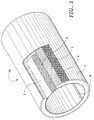
- a sleeve 30 according to the invention for a flexo printing or rotogravure printing roll as illustrated in Figure 1 consists of a base sleeve 1 of glass fiber reinforced plastic material, a layer 2 fastened thereupon of compressible material, a spacer layer 3 of foamed plastic material fastened thereupon, a cylindrical aluminum tube 4 fastened thereupon, and an engravable copper layer 5 fastened thereupon wherein the sleeve comprises an axially extending key 6 which engages in a groove in the flexo printing or rotogravure printing roll 31 (see Figures 2-9).
- the positive engagement between the flexo printing or rotogravure printing roll 31 and the sleeve 30 is accomplished by a conicality of the inside surface of the base sleeve 1 and a corresponding conicality of the flexo printing or rotogravure printing roll 31, both of which exhibit about a 2 mm change in diameter across the length of the axle.
- the mounting of the sleeve 30 onto the flexo printing or rotogravure printing roll 31 is particularly simple wherein the flexo printing or rotogravure printing roll 31 is clamped only on one side, whereafter the sleeve 30 is pushed on, and the final position is mechanically adjusted with a preset force.
- the base sleeve 1 and the layer of compressible material 2 are positioned into the aluminum pipe 4 and the space in between is filled with the spacer foam layer 3.
- the pushing on of the sleeve 30 onto the roll 31 may be performed manually.
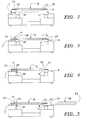
- the device for mounting the sleeve 30 onto the flexo printing or rotogravure printing roll 31 is accomplished in total in eight steps which are illustrated in the Figures 2 through 9.
- the flexo printing or rotogravure printing roll 31 having first and second ends 20, 21 and a central shaft 25 is placed onto the first and second support bearings 7, 8.
- the flexo printing or rotogravure printing roll 31 at the portion of the shaft 25 disposed adjacent to the left or first end of the roll 31 is securely clamped with a counter bearing 9.
- a support arm 10 is moved against the roll 31.
- the right or second support bearing 8 is lowered below the shaft 25. Supported by the counter bearing 9 at the left or first end 20 and the support arm 10, the flexo printing or rotogravure printing roll 31 now is free toward the right or second end 21.
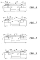
- the dismounting is accomplished as follows:
- the left support arm 10 is used as the push adaptor. It releases the sleeve 30. Therefore, the left support arm 10 has a double function as a support arm and push adaptor.
- the left support arm 10 supports the roll 31. Then, the takeaway of the sleeve 30 from the flexo printing or rotogravure printing roll 31 is accomplished in the same sequence as in the mounting thereof.
- the outer layer 5 may consist of a casting compound or hard foamed compound.
- the aluminum tube 4 may consist of plastic material or a plastic material reinforced with glass fiber or carbon fiber, respectively.
- the construction of the flexo sleeve 30 furthermore corresponds with the current manufacturing technology, i.e. it is a casting or hard foamed compound with a duromer surface.
Abstract
Description
Claims (16)
- A sleeve for a printing roll comprising:a base sleeve comprising a first end, a second end and an inside surface disposed therebetween, the inside surface of the base sleeve defining a tapered inside diameter of the base sleeve wherein the base sleeve is conical in shape with the inside diameter at the first end of the base sleeve being larger than the inside diameter at the second end of the base sleeve.
- The sleeve of claim 1 wherein the inside surface of the base sleeve further comprises an inwardly protruding key.
- The sleeve of claim 1 wherein the base sleeve is made from glass fiber reinforced plastic material.
- The sleeve of claim 1 wherein the base sleeve is made from aluminum.
- The sleeve of claim 1 wherein the inside diameter of the base sleeve at the first end thereof is about 2 mm larger than the inside diameter of the base sleeve at the second end thereof.
- The sleeve of claim 1 wherein the base sleeve further comprises an outer surface and a layer of compressible material is attached to the outer surface of the base sleeve.
- The sleeve of claim 6 further comprising a layer of foam material attached to the layer of compressible material.
- The sleeve of claim 7 further comprising an aluminum tube mounted onto the layer of foam material.
- The sleeve of claim 8 further comprising layer of engravable copper material attached to the aluminum tube.
- The sleeve of claim 8 further comprising layer of casting compound attached to the aluminum tube.
- The sleeve of claim 8 further comprising layer of a hard foamed compound attached to the aluminum tube.
- A method of mounting a printing sleeve onto a printing roll comprising the following steps:clamping the printing roll at a first end thereof, the printing roll comprising the first end, a second end and an outer surface defining an outside diameter of the printing roll, the printing roll having a tapered outside diameter wherein the printing roll is conical in shape with the outside diameter at the first end of the printing roll being larger than the outside diameter at the second end of the printing roll;pushing a first end of the sleeve over the second end of the printing roll, the base sleeve comprising the first end, a second end and an inside surface disposed therebetween, the inside surface of the base sleeve defining a tapered inside diameter of the base sleeve wherein the base sleeve is conical in shape with the inside diameter at the first end of the base sleeve being larger than the inside diameter at the second end of the base sleeve.
- The method of claim 12 wherein the pushing of the base sleeve over the printing roll is carried out with a predetermined force.
- The method of claim 12 wherein the pushing of the base sleeve over the printing roll is carried out manually.
- An apparatus for mounting a printing sleeve onto a printing roll,the printing roll comprising a first end, a second end and an outer surface defining an outside diameter of the printing roll, the printing roll having a tapered outside diameter wherein the printing roll is conical in shape with the outside diameter at the first end of the printing roll being larger than the outside diameter at the second end of the printing roll;the printing sleeve comprising a base sleeve comprising a first end a second end and an inside surface disposed therebetween, the inside surface of the base sleeve defining a tapered inside diameter of the base sleeve wherein the base sleeve is conical in shape with the inside diameter at the first end of the base sleeve being larger than the inside diameter at the second end of the base sleeve,the apparatus comprising:a first support bearing for supporting the first end of the printing roll,a second support bearing for supporting the second end of the printing roll,a clamp for clamping the first end of the printing roll onto the first support bearing,a support arm disposed between the first and second support bearings for balancing the printing roll and permitting removal of the second support bearing to permit the mounting of the first end of the printing sleeve over the second end of the printing roll,a push adaptor to push the first end of the printing sleeve toward the first end of the printing roll with a predetermined force.
- A method of mounting a printing sleeve onto a printing roll comprising the following steps:providing the printing roll comprising a first end, a second end and an outer surface defining an outside diameter of the printing roll, the printing roll having a tapered outside diameter wherein the printing roll is conical in shape with the outside diameter at the first end of the printing roll being larger than the outside diameter at the second end of the printing roll;providing the printing sleeve comprising a base sleeve comprising a first end, a second end and an inside surface disposed therebetween, the inside surface of the base sleeve defining a tapered inside diameter of the base sleeve wherein the base sleeve is conical in shape with the inside diameter at the first end of the base sleeve being larger than the inside diameter at the second end of the base sleeve,providing a first support bearing for supporting the first end of the printing roll, a second support bearing for supporting the second end of the printing roll, a clamp for clamping the first end of the printing roll onto the first support bearing, a support arm disposed between the first and second support bearings for balancing the printing roll, and a push adaptor to push the first end of the printing sleeve toward the first end of the printing roll,placing the first end of the printing roll onto the first support bearing,placing the second end of the printing roll onto the second support bearing,clamping the first end of the printing roll against the first support bearing with the clamp,engaging the printing roll with the support arm,removing the second support bearing so that it no longer engages the second end of the printing roll,mounting the first end of the printing sleeve over the second end of the printing roll,sliding the first end of the printing sleeve toward the first end of the printing roll and the second end of the printing sleeve past the push adaptor,returning the second support bearing so that it engages the second end of the printing roll,releasing the support arm so that it no longer engages the printing roll,engaging the printing sleeve with the push adaptor,pushing the first end of the printing sleeve toward the first end of the printing roll with a predetermined force.
Applications Claiming Priority (2)
| Application Number | Priority Date | Filing Date | Title |
|---|---|---|---|
| US08/812,527 US5797322A (en) | 1996-01-31 | 1997-03-07 | Printing sleeve for a flexographic or gravure printing roll |
| US812527 | 1997-03-07 |
Publications (1)
| Publication Number | Publication Date |
|---|---|
| EP0865933A1 true EP0865933A1 (en) | 1998-09-23 |
Family
ID=25209849
Family Applications (1)
| Application Number | Title | Priority Date | Filing Date |
|---|---|---|---|
| EP98103858A Withdrawn EP0865933A1 (en) | 1997-03-07 | 1998-03-05 | Sleeve for rotogravure printing rolls, method of manufacture thereof, and method of the use thereof |
Country Status (2)
| Country | Link |
|---|---|
| US (1) | US5797322A (en) |
| EP (1) | EP0865933A1 (en) |
Cited By (2)
| Publication number | Priority date | Publication date | Assignee | Title |
|---|---|---|---|---|
| EP1967360A2 (en) | 2007-03-08 | 2008-09-10 | Saueressig Gmbh & Co. | Sleeve and clamp tool for use in a system comprising one clamp tool and at least one sleeve |
| DE102015102906A1 (en) * | 2015-02-28 | 2016-09-01 | Gt+W Gmbh | printing device |
Families Citing this family (25)
| Publication number | Priority date | Publication date | Assignee | Title |
|---|---|---|---|---|
| US6409645B1 (en) * | 1997-06-13 | 2002-06-25 | Sw Paper Inc. | Roll cover |
| JP3670453B2 (en) * | 1997-08-25 | 2005-07-13 | 富士写真フイルム株式会社 | Conveyance roller structure |
| DE19756327A1 (en) * | 1997-12-18 | 1999-07-01 | Polywest Kunststofftechnik | Mold for rotary printing, coating or embossing of sheet-like materials and method for producing the mold |
| US6224526B1 (en) * | 1997-12-19 | 2001-05-01 | H.B. Fuller Licensing & Financing, Inc. | Printing rollers |
| DE19804269A1 (en) * | 1998-02-04 | 1999-08-05 | Heidelberger Druckmasch Ag | Device for applying a liquid to a printing material sheet, in particular printing, or coating unit, in a sheet-fed rotary printing machine |
| DE19914709B4 (en) * | 1999-03-31 | 2010-04-29 | Voith Patent Gmbh | Roller, in particular for smoothing paper webs, and method for producing such a roller |
| DE19914708B4 (en) * | 1999-03-31 | 2009-07-30 | Voith Patent Gmbh | Roller, in particular for smoothing paper webs, and method for producing such a roller |
| US6314879B1 (en) * | 1999-05-12 | 2001-11-13 | Hurletron Incorporated | Flexographic printing apparatus |
| US20110045267A1 (en) * | 1999-10-13 | 2011-02-24 | Hatec Produktions- und Handels- gesellschaft mbH | Substructure material for a printing device and printer's blanket for the printing of uneven materials to be printed |
| FR2801833B1 (en) * | 1999-12-03 | 2003-05-16 | Rollin Sa | A SLEEVE COMPRISING A SOLIDARIZATION LAYER ON A METAL SUPPORT CYLINDER |
| DE10024001B4 (en) * | 2000-05-17 | 2014-11-13 | Manroland Web Systems Gmbh | Format-variable web offset printing press and method for producing format-variable surfaces |
| FR2811256A1 (en) * | 2000-07-06 | 2002-01-11 | Jean Francille | Production of casing with compensation bridges, for flexography, has composite material comprising several layers wound helicoidally and impregnated with resins |
| US6939279B2 (en) * | 2001-05-01 | 2005-09-06 | Ten Cate Enbi | Tire for skew reducing roller |
| US6769363B2 (en) * | 2001-06-27 | 2004-08-03 | Heidelberger Druckmaschinen Ag | Device and method for manufacturing a tubular printing blanket |
| US6703095B2 (en) | 2002-02-19 | 2004-03-09 | Day International, Inc. | Thin-walled reinforced sleeve with integral compressible layer |
| US6874232B2 (en) | 2003-05-21 | 2005-04-05 | Stowe Woodward, Llc | Method for forming cover for industrial roll |
| US20050153821A1 (en) * | 2004-01-09 | 2005-07-14 | Grigoriy Grinberg | Method of making a metal outer surface about a composite or polymer cylindrical core |
| DE102004015248A1 (en) * | 2004-03-29 | 2005-10-13 | Goss International Montataire S.A. | Lifting sleeve for a printing cylinder of an offset printing machine |
| DE102004043088A1 (en) * | 2004-09-07 | 2006-03-09 | Man Roland Druckmaschinen Ag | Sleeve for a printing machine cylinder and printing press cylinder |
| US20060137551A1 (en) * | 2004-12-23 | 2006-06-29 | Duchenaud Uniflexo | Compensator sleeve for flexographic printing |
| US10287731B2 (en) * | 2005-11-08 | 2019-05-14 | Stowe Woodward Licensco Llc | Abrasion-resistant rubber roll cover with polyurethane coating |
| DE102006002029A1 (en) * | 2006-01-13 | 2007-07-19 | Bielomatik Jagenberg Gmbh + Co. Kg | Braking device for stopping stacking of paper or cardboard sheets comprises clamping elements with annular clamping zones on a part of the periphery and a deviating unit arranged in the running direction of the sheets |
| CN101045367A (en) * | 2006-03-28 | 2007-10-03 | 海德堡印刷机械股份公司 | Overlapping curve roller printing device |
| CN104552086A (en) * | 2014-12-26 | 2015-04-29 | 镇江鼎胜铝业股份有限公司 | Sleeve assembly clamp of aluminum processing equipment |
| IT201800003625A1 (en) * | 2018-03-15 | 2019-09-15 | Rossini S P A | SLEEVE FOR ROTOCALCO PRINTING |
Citations (5)
| Publication number | Priority date | Publication date | Assignee | Title |
|---|---|---|---|---|
| US3858287A (en) * | 1972-03-06 | 1975-01-07 | Albert B Christoffersen | Impression cylinder |
| EP0181726A2 (en) * | 1984-10-29 | 1986-05-21 | Drg (Uk) Limited | Printing roll with detachable sleeve |
| EP0295319A1 (en) * | 1987-06-19 | 1988-12-21 | Saueressig Gmbh & Co. | Engraved cylinder composed of a core and a detachable sleeve |
| US5289769A (en) * | 1992-08-17 | 1994-03-01 | W. O. Hickok Mfg., Co. | Method and apparatus for changing a printing sleeve |
| EP0787597A2 (en) * | 1996-01-31 | 1997-08-06 | POLYWEST KUNSTSTOFFTECHNIK Saueressig & Partner GmbH & Co. KG | Sleeve for an intaglio printing cylinder, fabrication process therefore and working procedure of the manufacturing machine |
Family Cites Families (7)
| Publication number | Priority date | Publication date | Assignee | Title |
|---|---|---|---|---|
| US1493257A (en) * | 1923-05-22 | 1924-05-06 | Charles C Garner | Ink-feeding roller |
| US3467009A (en) * | 1965-07-06 | 1969-09-16 | Grace W R & Co | Compressible printing roll |
| CH497283A (en) * | 1969-10-27 | 1970-10-15 | De La Rue Giori Sa | Printing cylinder for steel engraving machines |
| US3750250A (en) * | 1972-08-31 | 1973-08-07 | Bingham S Co | Printer{40 s roller and method of making same |
| US4144812A (en) * | 1975-01-08 | 1979-03-20 | Strachan & Henshaw Limited | Printing sleeves |
| JPS5936133B2 (en) * | 1979-08-10 | 1984-09-01 | 山内ゴム工業株式会社 | Polyurethane rubber roll and its manufacturing method |
| GB8312384D0 (en) * | 1983-05-05 | 1983-06-08 | Drg Uk Ltd | Printing roll with detachable sleeve |
-
1997
- 1997-03-07 US US08/812,527 patent/US5797322A/en not_active Expired - Fee Related
-
1998
- 1998-03-05 EP EP98103858A patent/EP0865933A1/en not_active Withdrawn
Patent Citations (5)
| Publication number | Priority date | Publication date | Assignee | Title |
|---|---|---|---|---|
| US3858287A (en) * | 1972-03-06 | 1975-01-07 | Albert B Christoffersen | Impression cylinder |
| EP0181726A2 (en) * | 1984-10-29 | 1986-05-21 | Drg (Uk) Limited | Printing roll with detachable sleeve |
| EP0295319A1 (en) * | 1987-06-19 | 1988-12-21 | Saueressig Gmbh & Co. | Engraved cylinder composed of a core and a detachable sleeve |
| US5289769A (en) * | 1992-08-17 | 1994-03-01 | W. O. Hickok Mfg., Co. | Method and apparatus for changing a printing sleeve |
| EP0787597A2 (en) * | 1996-01-31 | 1997-08-06 | POLYWEST KUNSTSTOFFTECHNIK Saueressig & Partner GmbH & Co. KG | Sleeve for an intaglio printing cylinder, fabrication process therefore and working procedure of the manufacturing machine |
Cited By (5)
| Publication number | Priority date | Publication date | Assignee | Title |
|---|---|---|---|---|
| EP1967360A2 (en) | 2007-03-08 | 2008-09-10 | Saueressig Gmbh & Co. | Sleeve and clamp tool for use in a system comprising one clamp tool and at least one sleeve |
| DE102007011252A1 (en) | 2007-03-08 | 2008-09-11 | Saueressig Gmbh & Co. | Sleeve and clamping tool for use in a system of a clamping tool and at least one sleeve |
| DE102007011252B4 (en) * | 2007-03-08 | 2011-04-28 | Saueressig Gmbh & Co. | Sleeve and clamping tool for use in a system of a clamping tool and at least one sleeve and method for producing a sleeve |
| DE102015102906A1 (en) * | 2015-02-28 | 2016-09-01 | Gt+W Gmbh | printing device |
| DE102015102906B4 (en) | 2015-02-28 | 2019-07-25 | Gt+W Gmbh | Printing device for high pressure and gravure printing |
Also Published As
| Publication number | Publication date |
|---|---|
| US5797322A (en) | 1998-08-25 |
Similar Documents
| Publication | Publication Date | Title |
|---|---|---|
| EP0865933A1 (en) | Sleeve for rotogravure printing rolls, method of manufacture thereof, and method of the use thereof | |
| US5784961A (en) | Method and apparatus for mounting a printing sleeve onto a printing roll | |
| US4913048A (en) | Method and apparatus for printing with a lithographic sleeve | |
| US5904095A (en) | Bridge mandrel for flexographic printing presses | |
| US4685393A (en) | Rotogravure cylinder comprising a core and a shell detachably joined thereto | |
| CA2284172C (en) | Method and apparatus for fitting a printing plate to a plate cylinder | |
| DE69431202D1 (en) | CARRIER DEVICE AND METHOD FOR LOW PRINTING CYLINDERS | |
| CN109195800B (en) | Drum with partially gas-permeable surface | |
| EP1164011A3 (en) | Multi-layered printing sleeve | |
| FI103330B (en) | Method of pulling bearings, bearing puller and its use | |
| US6792858B2 (en) | Device for handling printing cylinder sleeves | |
| PA8458801A1 (en) | DISTRIBUTOR FOR CORES OF NUCLEOUS PRODUCTS | |
| CA2001595C (en) | System for releasably coupling a stub shaft extending from a printing cylinder to a shaft passing through a machine side wall | |
| CA1302126C (en) | Resilient wedge for core expander tool | |
| EP0000410A1 (en) | Rotary printing cylinder | |
| US20090044713A1 (en) | Gravure Printing-Form Sleeve and Production Thereof | |
| US6367684B1 (en) | Method and device for working a weld on a support sleeve | |
| EP0925244B1 (en) | Method for unwinding rolls of paper | |
| US7077062B2 (en) | Sleeve-like printing or transfer form and device for chamfering the longitudinal ends of a sleeve-like printing or transfer form | |
| US6701838B2 (en) | Engraved transfer cylinder for a flexographic printing press | |
| CN210457017U (en) | Double-end supporting take-up and pay-off roller of printing machine | |
| EP1087267A3 (en) | Apparatus and method to fix a toner image on an image carrier | |
| ES2115494B1 (en) | DEVICE FOR FIXING KNOBS TO LEVER ARMS FOR GEARBOXES OF AUTOMOBILE VEHICLES. | |
| US20080276814A1 (en) | Web press and method for producing the press | |
| CN217021911U (en) | Quick assembling and disassembling tool for ink roller bearing of cigarette making machine |
Legal Events
| Date | Code | Title | Description |
|---|---|---|---|
| PUAI | Public reference made under article 153(3) epc to a published international application that has entered the european phase |
Free format text: ORIGINAL CODE: 0009012 |
|
| AK | Designated contracting states |
Kind code of ref document: A1 Designated state(s): AT BE CH DE DK ES FI FR GB GR IE IT LI LU NL PT SE |
|
| AX | Request for extension of the european patent |
Free format text: AL;LT;LV;MK;RO;SI |
|
| 17P | Request for examination filed |
Effective date: 19990313 |
|
| AKX | Designation fees paid |
Free format text: AT BE CH DK ES FI FR GB GR IE IT LI LU NL PT SE |
|
| RBV | Designated contracting states (corrected) |
Designated state(s): AT BE CH DK ES FI FR GB GR IE IT LI LU NL PT SE |
|
| REG | Reference to a national code |
Ref country code: DE Ref legal event code: 8566 |
|
| RBV | Designated contracting states (corrected) |
Designated state(s): AT BE CH DE DK ES FI FR GB GR IE IT LI LU NL PT SE |
|
| 17Q | First examination report despatched |
Effective date: 19991217 |
|
| STAA | Information on the status of an ep patent application or granted ep patent |
Free format text: STATUS: THE APPLICATION HAS BEEN WITHDRAWN |
|
| 18W | Application withdrawn |
Withdrawal date: 20000426 |