EP0865332B1 - Tube forming on an end fitting - Google Patents
Tube forming on an end fitting Download PDFInfo
- Publication number
- EP0865332B1 EP0865332B1 EP96935849A EP96935849A EP0865332B1 EP 0865332 B1 EP0865332 B1 EP 0865332B1 EP 96935849 A EP96935849 A EP 96935849A EP 96935849 A EP96935849 A EP 96935849A EP 0865332 B1 EP0865332 B1 EP 0865332B1
- Authority
- EP
- European Patent Office
- Prior art keywords
- tube
- end fitting
- torque
- fitting
- tubular body
- Prior art date
- Legal status (The legal status is an assumption and is not a legal conclusion. Google has not performed a legal analysis and makes no representation as to the accuracy of the status listed.)
- Expired - Lifetime
Links
- 238000000034 method Methods 0.000 claims description 29
- 229910052751 metal Inorganic materials 0.000 claims description 26
- 239000002184 metal Substances 0.000 claims description 26
- 230000008569 process Effects 0.000 claims description 22
- 238000010168 coupling process Methods 0.000 claims description 19
- 238000005859 coupling reaction Methods 0.000 claims description 19
- 230000008878 coupling Effects 0.000 claims description 18
- 230000007797 corrosion Effects 0.000 claims description 11
- 238000005260 corrosion Methods 0.000 claims description 11
- 239000000565 sealant Substances 0.000 claims description 8
- 229910001250 2024 aluminium alloy Inorganic materials 0.000 claims description 6
- 238000005336 cracking Methods 0.000 claims description 6
- 230000000630 rising effect Effects 0.000 claims description 4
- 230000001052 transient effect Effects 0.000 claims 13
- 230000000452 restraining effect Effects 0.000 claims 3
- 230000001939 inductive effect Effects 0.000 claims 2
- 239000000463 material Substances 0.000 description 23
- 239000012212 insulator Substances 0.000 description 12
- 239000003990 capacitor Substances 0.000 description 11
- 238000004519 manufacturing process Methods 0.000 description 11
- 229910052782 aluminium Inorganic materials 0.000 description 10
- XAGFODPZIPBFFR-UHFFFAOYSA-N aluminium Chemical compound [Al] XAGFODPZIPBFFR-UHFFFAOYSA-N 0.000 description 10
- 230000035882 stress Effects 0.000 description 5
- 229910000831 Steel Inorganic materials 0.000 description 4
- 230000033001 locomotion Effects 0.000 description 4
- 239000010959 steel Substances 0.000 description 4
- 238000010438 heat treatment Methods 0.000 description 3
- 238000009413 insulation Methods 0.000 description 3
- 238000012986 modification Methods 0.000 description 3
- 230000004048 modification Effects 0.000 description 3
- 229910001220 stainless steel Inorganic materials 0.000 description 3
- 239000010935 stainless steel Substances 0.000 description 3
- 238000003860 storage Methods 0.000 description 3
- RYGMFSIKBFXOCR-UHFFFAOYSA-N Copper Chemical group [Cu] RYGMFSIKBFXOCR-UHFFFAOYSA-N 0.000 description 2
- XEEYBQQBJWHFJM-UHFFFAOYSA-N Iron Chemical compound [Fe] XEEYBQQBJWHFJM-UHFFFAOYSA-N 0.000 description 2
- PXHVJJICTQNCMI-UHFFFAOYSA-N Nickel Chemical compound [Ni] PXHVJJICTQNCMI-UHFFFAOYSA-N 0.000 description 2
- 239000004699 Ultra-high molecular weight polyethylene Substances 0.000 description 2
- 230000002411 adverse Effects 0.000 description 2
- 230000008901 benefit Effects 0.000 description 2
- 238000005219 brazing Methods 0.000 description 2
- 238000001816 cooling Methods 0.000 description 2
- 239000002360 explosive Substances 0.000 description 2
- 239000011152 fibreglass Substances 0.000 description 2
- 210000001503 joint Anatomy 0.000 description 2
- 238000004513 sizing Methods 0.000 description 2
- 239000000126 substance Substances 0.000 description 2
- 229920000785 ultra high molecular weight polyethylene Polymers 0.000 description 2
- 238000003466 welding Methods 0.000 description 2
- 238000004804 winding Methods 0.000 description 2
- OKTJSMMVPCPJKN-UHFFFAOYSA-N Carbon Chemical compound [C] OKTJSMMVPCPJKN-UHFFFAOYSA-N 0.000 description 1
- VYZAMTAEIAYCRO-UHFFFAOYSA-N Chromium Chemical compound [Cr] VYZAMTAEIAYCRO-UHFFFAOYSA-N 0.000 description 1
- 239000004698 Polyethylene Substances 0.000 description 1
- 238000003070 Statistical process control Methods 0.000 description 1
- 239000004809 Teflon Substances 0.000 description 1
- 229920006362 Teflon® Polymers 0.000 description 1
- 208000027418 Wounds and injury Diseases 0.000 description 1
- 230000009471 action Effects 0.000 description 1
- 230000032683 aging Effects 0.000 description 1
- 230000003466 anti-cipated effect Effects 0.000 description 1
- DMFGNRRURHSENX-UHFFFAOYSA-N beryllium copper Chemical compound [Be].[Cu] DMFGNRRURHSENX-UHFFFAOYSA-N 0.000 description 1
- 230000005540 biological transmission Effects 0.000 description 1
- 230000015572 biosynthetic process Effects 0.000 description 1
- 229910052799 carbon Inorganic materials 0.000 description 1
- 229910052804 chromium Inorganic materials 0.000 description 1
- 239000011651 chromium Substances 0.000 description 1
- 238000000576 coating method Methods 0.000 description 1
- 239000002826 coolant Substances 0.000 description 1
- 229910052802 copper Inorganic materials 0.000 description 1
- 239000010949 copper Substances 0.000 description 1
- 230000006378 damage Effects 0.000 description 1
- 238000013461 design Methods 0.000 description 1
- 238000006073 displacement reaction Methods 0.000 description 1
- 239000013013 elastic material Substances 0.000 description 1
- 238000010292 electrical insulation Methods 0.000 description 1
- 239000003792 electrolyte Substances 0.000 description 1
- 238000005516 engineering process Methods 0.000 description 1
- 230000007613 environmental effect Effects 0.000 description 1
- 239000012530 fluid Substances 0.000 description 1
- 208000014674 injury Diseases 0.000 description 1
- 238000003780 insertion Methods 0.000 description 1
- 230000037431 insertion Effects 0.000 description 1
- 238000007689 inspection Methods 0.000 description 1
- 229910052742 iron Inorganic materials 0.000 description 1
- 239000000314 lubricant Substances 0.000 description 1
- 238000003754 machining Methods 0.000 description 1
- 230000007246 mechanism Effects 0.000 description 1
- 150000002739 metals Chemical class 0.000 description 1
- 239000000203 mixture Substances 0.000 description 1
- 229910052759 nickel Inorganic materials 0.000 description 1
- 239000012811 non-conductive material Substances 0.000 description 1
- 239000000615 nonconductor Substances 0.000 description 1
- 239000003973 paint Substances 0.000 description 1
- 230000002093 peripheral effect Effects 0.000 description 1
- -1 polyethylene Polymers 0.000 description 1
- 229920000573 polyethylene Polymers 0.000 description 1
- 235000013824 polyphenols Nutrition 0.000 description 1
- 238000002360 preparation method Methods 0.000 description 1
- 238000011160 research Methods 0.000 description 1
- 230000000717 retained effect Effects 0.000 description 1
- 150000003839 salts Chemical class 0.000 description 1
- 238000004904 shortening Methods 0.000 description 1
- 125000006850 spacer group Chemical group 0.000 description 1
- 239000007921 spray Substances 0.000 description 1
- 230000002459 sustained effect Effects 0.000 description 1
- 238000012360 testing method Methods 0.000 description 1
- 238000013519 translation Methods 0.000 description 1
- 238000007514 turning Methods 0.000 description 1
- XLYOFNOQVPJJNP-UHFFFAOYSA-N water Substances O XLYOFNOQVPJJNP-UHFFFAOYSA-N 0.000 description 1
Images














Classifications
-
- B—PERFORMING OPERATIONS; TRANSPORTING
- B21—MECHANICAL METAL-WORKING WITHOUT ESSENTIALLY REMOVING MATERIAL; PUNCHING METAL
- B21D—WORKING OR PROCESSING OF SHEET METAL OR METAL TUBES, RODS OR PROFILES WITHOUT ESSENTIALLY REMOVING MATERIAL; PUNCHING METAL
- B21D26/00—Shaping without cutting otherwise than using rigid devices or tools or yieldable or resilient pads, i.e. applying fluid pressure or magnetic forces
- B21D26/14—Shaping without cutting otherwise than using rigid devices or tools or yieldable or resilient pads, i.e. applying fluid pressure or magnetic forces applying magnetic forces
-
- F—MECHANICAL ENGINEERING; LIGHTING; HEATING; WEAPONS; BLASTING
- F16—ENGINEERING ELEMENTS AND UNITS; GENERAL MEASURES FOR PRODUCING AND MAINTAINING EFFECTIVE FUNCTIONING OF MACHINES OR INSTALLATIONS; THERMAL INSULATION IN GENERAL
- F16D—COUPLINGS FOR TRANSMITTING ROTATION; CLUTCHES; BRAKES
- F16D1/00—Couplings for rigidly connecting two coaxial shafts or other movable machine elements
- F16D1/06—Couplings for rigidly connecting two coaxial shafts or other movable machine elements for attachment of a member on a shaft or on a shaft-end
- F16D1/064—Couplings for rigidly connecting two coaxial shafts or other movable machine elements for attachment of a member on a shaft or on a shaft-end non-disconnectable
- F16D1/072—Couplings for rigidly connecting two coaxial shafts or other movable machine elements for attachment of a member on a shaft or on a shaft-end non-disconnectable involving plastic deformation
Definitions
- This invention relates to an end fitting according to the preamble of claim 1 (see for example US-A-5 304 012), onto which the ends of the torque tubes may be electromagnetically formed using tubing material as purchased without preliminary heat treating and storage at cold temperatures and to a tube forming apparatus for electromagnetically deforming the end of a tube onto a such end fitting to form a torque transmitting mechanical joint between the tube and the insert that is as strong or stronger than the tube itself and is very fatigue resistant.
- Electro-magnetic forming is especially appealing because of the potential for efficient, high volume, precisely repeatable production processes, but existing apparatus and techniques to deform aluminum tubing materials possessing the required properties of high strength and corrosion cracking resistance have resulted in formation of cracks in the tubing during forming onto the end fitting. The resulting cracks are unacceptable because of the shortening of the fatigue life of the torque tube.
- Electromagnetically pulse forming 2024 aluminum tubing in the T-3 condition onto end fittings shown in U.S. Patent No. 4,523,872 using an "exploding coil" for electromagnetically forming the 2024 aluminum was time consuming, because a new coil was needed for each forming operation.
- the exploding coil literally burst like a hand grenade, creating a shower of copper wire fragments that required careful shielding to prevent injury to the workers, and to protect them from the loud noise involved in the operation.
- the production equipment used to form the tubing around the end fittings must be durable, repeatable and accurate. That is, it must be capable of producing many parts without wear or need for adjustment.
- the parts it produces must always be the same for a given setting of the equipment, and the equipment must be capable of easily, quickly and accurately indexing the parts to be formed in exactly the same place so they are positioned accurately with respect to each other and with respect to the equipment each time a torque tube is made.
- the components of the equipment must be accurately positioned relative to each other the same way each time the tube is formed on an end fitting so that substantially identical torque tubes are made using identical settings of the equipment and acting on identical parts.
- an apparatus for electromagnetic pulse forming an end fitting on an aluminum tube for manufacture of torque tubes, push rods and other such devices should form acceptable joints even if the tubing material were primed with corrosion protection coatings before forming, and should be useful to form the end of the tube onto the end fitting without further preparation such as sizing, heat treating or freezer storage.
- the process for such an optimal system would produce very little or no scrap or rework, would be low in production cost, and would produce a torque coupling to the tube material that would be stronger than the tube itself and, when used to make torque tubes for aviation applications, would withstand fatigue loading for a period exceeding about four times the service life of an airplane.
- an object of this invention to provide an end fitting for connection to the end of a conductive metal tube by electromagnetically forming. This object is achieved by an end fitting according to claim 1.
- Another object of this invention is to provide an apparatus for forming the end of a conductive metal tube onto an end fitting for connection to the end of a conductive metal tube by electro-magnetically forming the tube end around the end fitting. This object is achieved by an apparatus according to claim 20.
- Still another object of this invention is to provide a process of making a torque tube having fittings magnetically formed onto its ends. This object is achieved by a process according to claim 16.
- a further object of this invention is to provide an improved process of transmitting torque from a driver at one end of a torque tube to a driven device at the other end of the torque tube wherein torque is transmitted through end fittings on the tube to the tubing material by virtue of the tubing material having been deformed around the fitting, and to provide a process for forming a metal tube onto an end fitting according to the invention.
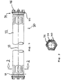
- a torque tube 30 made by the apparatus of this invention having an elongated cylindrical tube 32 having a longitudinal axis 33, and an end fitting 34 fixed coaxially in the tube 32 at each end.
- the tube 32 is preferably 2024 aluminum, purchased from the supplier in the T-3 temper. Pesheney, an aluminum manufacturer in France, supplies 2024 tubing in various diameters and wall thicknesses that are suitable for use in these torque tubes, although other materials can be used, depending on the anticipated maximum loads, fatigue life and chemical environment the torque tube can be expected to encounter.
- the end fittings 34 are designed to be fixed in the ends of the tube 32 by forming the tube around the end fitting.
- a host of forming techniques are known and could be used for this purpose, such as swaging, hydroforming, explosive forming, etc.
- the preferred manufacturing technique for fixing the end fittings 34 in the ends of the tubes 32 is electromagnetic pulse forming, explained in detail below, which requires that the tube 32 be electrically conductive or, if not, must be provided with a conductive sleeve in which eddy currents can be magnetically induced in the forming process. If a conductive sleeve is used over a tube of material such as stainless steel having lower conductivity, the discussion below regarding the generation of opposing magnetic fields in the tube pertains to the conductive sleeve.
- the end fitting 34 is preferably made of 15-5 stainless steel having 15% chromium, 5% nickel, 4% copper and the balance iron with less than about 1% carbon. Naturally, other materials could be used for the fitting 34, but 15-5 stainless steel is used because of its combination of corrosion resistance, machineability and strength.
- the fitting 34 has a tubular body 36 having an inner axial end 35 and a longitudinal axis 37 which, in the assembled torque tube 30, is coincident with the axis 33 of the tube 32.
- a torque coupling 38 is integral with the end fitting 34 at one axial end of the tubular body 36.
- An axial bore 40 extends through the tubular body 36, and is beveled at each end 41 to save weight.
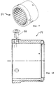
- An enlarged counterbore 42 coaxial with the axial bore 40, extends through the torque coupling 38, as best shown in Fig. 6.
- Either or both torque couplings 38 on the end fittings at the two ends of the torque tube 30 could be components of a U-joint or other conventional coupling device, but the coupling 38 in this preferred embodiment is a splined annulus 44 having three axially protruding nubs 46 circumferentially spaced equally around the annulus 44.
- Each nub 46 has a radial hole 48 extending completely through the nub and communicating with the axial counterbore 42.
- Each hole 48 receives a threaded insert 50, shown in Fig. 6, to receive screws 52 for holding a coaxial, internally splined sleeve 54 axially in place around the splined annulus 44.
- the sleeve 54 illustrated in Figs.
- the torque tube 30 couples the torque tube 30 to a driving or driven gear in the mechanical system in which it operates.
- the torque tube 30 is driven by a hydraulic motor and drives a pinion gear for driving a gear rack when the leading edge slats are to be extended or retracted for take-off and landing.
- the sleeve 54 enables the torque tube 30 to flex angularly with respect to the driving gear or coupled mechanism while remaining in torque-coupled relationship thereto, and also permits a limited degree of axial displacement of the torque tube 30 to accommodate wing deflection in flight.
- FIG. 4 As shown best in Fig. 4, six flat lands 56 are milled onto the surface of the center section 57 of the tubular body 36, forming a cross section through the axis 37 approximately in the form of a regular polygon, preferably a hexagon, as illustrated in Fig. 8.
- the flat lands 56 terminate axially short of both ends of the tubular body 36, leaving the two end portions of the tubular body 36, each in the form of a circular cross-section cylinder extending axially slightly beyond the hexagonal center section, providing an end supporting surface 58 and a center supporting surface 60 for the tube 32 on both axial ends of the flat lands 56 when the tube is electro-magnetically pulse formed down into the flat lands 56.
- the axial ends of the flat lands 56 blend onto the supporting surfaces 58 and 60 with sloping shoulders 62 and 64, respectively, lying at an angle of between 30-55°, preferably about 45° from the horizontal, around which the 2024 aluminum of the tube 32 can be formed in the T-3 condition without cracking.
- Electromagnetically forming the aluminum tube 32 onto the hexagonal center section 57 of the end fitting 34 establishes a torque transmitting joint between the end fitting 34 and the tube 32 that is stronger torsionally than the tubing material itself.
- Axial load transmission between the tube 32 and the end fitting is established by engagement of the shoulders 62 and 64 on the end fitting with portions of the tube 32 formed over the shoulders.
- a groove 66 is milled into the flat face of each land 56 as shown best in Figs. 6 and 8.
- the groove 66 is a simple circular cross-section groove cut with a simple spherical end cutter.
- the groove 66 provides a runout region for the tube 32 to expand into when it is electromagnetically formed around the end fitting 34 so it does not rebound away from the flat face of the lands 56 by springback or reflection. This ensures that the tube material remains under slight tension after it is formed around the end fitting 34, so it retains a slight hoop stress and maintains a tight torsional joint on the end fitting 34.
- the dimensions of the groove 66 are not critical and need not be held to close tolerances, so the machining on the groove is not a costly operation.
- the shape of the groove 66 should be conducive to receiving the tube material as it is impulse formed onto the fitting 34 and avoid any sharp bends or folds of the material when it forms down into the grooves 66.
- the radius of curvature of the circular groove 66 should be greater than about 10% of the radius of the axial bore 40, and less than one third of the point-to-point dimension of the face of the hexagonal surface in which the groove is formed.
- the splined annulus 44 extends radially from an enlarged diameter step 68 at the inner end of the tubular body 36.
- the step 68 forms a shoulder 70 with the tubular body 36 at the junction with the center cylindrical supporting surface 60.
- the fillet 72 avoids creating a stress riser at that inside corner, and the gap 74 provides a space in which sealant can be applied and retained to seal the interface between the end fitting 34 and the tube 32.
- the protruding nubs 46 have axial end faces 76 which are machined precisely to give the distal end portion 78 of the end fitting 34, indicated in Fig. 7 as that portion between the shoulder 70 and the axial end faces 76 of the protruding nubs 46, a known dimension that is useful for forming the second end of the tube 32 onto an end fitting 34 after the first end has been formed on a forming apparatus 100, to be described below.
- the forming apparatus 100 performs the process of electromagnetically forming the aluminum tubing 32 onto end fittings 34 to manufacture the torque tubes 30 in accordance with this invention.
- This apparatus could also be used for manufacturing other types of tubes with end fittings and even for down-sizing tube ends. It is fast, easy to use, safe, quiet, reliable, repeatable and is capable of production at a sustained rate.
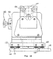
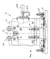
- the apparatus 100 includes a tube support assembly 102 for holding the tube 32 while the end fitting 34 is inserted and properly positioned in the end of the tube 32 and for moving the tube 32 and the installed end fitting 34 into an opening 103 in a main coil 104 where the tube is electromagnetically formed onto the end fitting 34 with electrical power supplied through a conduit 105 from a power supply cabinet 106 holding a power supply, a capacitor bank, and electronic controls for powering the main coil 104. Power from the capacitors in the cabinet 106 is delivered along fifteen cables in the conduit 105 to a power bus in a housing 107 atop the main coil 104, to which the power bus is electrically connected.
- a chiller 109 cools a coolant that is pumped through cooling channels in the main coil 104 to remove heat generated during operation of the apparatus 100.
- the main coil 104 and power supply cabinet 106 (and associated components) are available commercially from Elmag, Inc. of San Diego, California as the "Magnepuls” Electromagnetic Energy Pulse System.
- the tube support assembly 102 includes an elongated table 108 on which two pairs of rails 110 are mounted for supporting a front carriage 112 and a rear carriage 114 for longitudinal translation on the rails 110.
- a connecting bar 120 is fastened between the front carriage 112 and the rear carriage 114 to ensure that both carriages 112 and 114 move together.
- the rear end of the connecting bar 120 is supported on a traveling block 121.
- a hand wheel 122 on a clamp bolt threaded into a U-bracket 124 on the rear carriage 114 permits the spacing between the front and rear carriages to be adjusted.
- Wheels 123 support the front and rear carriages 112 and 114 and the traveling block 121 for smooth linear motion along the rails 110.
- a control valve 125 controls the flow of air under pressure from an air pressure source through a supply line 127 to air lines 129 to a selected end of the air cylinders 118 so the carriages may be driven in either direction by operating the control valve in one direction or the other.
- a digital indicator 130 on a display 132 indicates the longitudinal position of the rear carriage 114 as sensed by the sensor 126.
- Each carriage 112 and 114 includes a self-centering, pneumatically actuated three-roller tube clamp 134 such as the Autoblock #MWR 21/75 commercially available from Reynolds Machine and Tool Co., in Melrose Park, IL.
- the tube clamps 134 are mounted atop the carriages 112 and 114 for gripping and centering the tube 32 when valve handles 135 on a pneumatic control assembly 136 are moved.
- the use of self-centering clamps 1345 allows all sizes of the tube 32 to be loaded on their respective centerlines so the tube always aligns with the center of the forming coil 104, to be described below, and allows rotation of the tubing after clamping.
- a back stop 138 is mounted on the rear carriage 114 intersecting the axis of the tube clamps 134 to provide a reference surface against which the tube 32 can be abutted.
- the known length of the tube 32 can be used with the longitudinal scale 128 and sensor 126 to accurately position the end of the tube 32 relative to the nested end fitting 34 in the main coil 104, as is explained below.
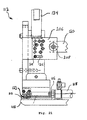
- a tube locator assembly 150 shown in Figs. 22 and 23, includes an attachment block 152 by which the tube locator assembly 150 is attached to the front carriage 112, and an insulator block 154 fastened at one end to the attachment block 152.
- the insulator block is made of some suitable non-conductive material such as ultra-high molecular weight polyethylene, which is not only a good electrical insulator and a durable material, but also withstands the harmonics created by the electromagnetic forming pulse better than phenolics normally used in applications of this kind.
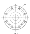
- a circumferential flange 155 of a field concentrator 156 is fastened by screws 157 at one end to the other end of the insulator block 154, as shown in Fig. 23.
- a locator block 158 also made of ultra-high molecular weight polyethylene, is fastened to the other end of the lower half of the field concentrator 156.
- the locator block 158 is supported vertically for sliding movement on an upwardly opening semi-cylindrical channel 159 on the top of a cradle block 160 fastened to the facing surface of the main coil assembly 104.
- the insulator block 154 and field concentrator 156 are split on a horizontal plane through the longitudinal axis of the insulator block 154 and the field concentrator 156 into upper and lower diametrical halves, for ease of insertion of the tube 32 and its nested end fitting 34 into the field concentrator 156 for forming, as described below.
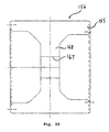
- a tube locator 162 in an axial bore 164 in the locator block 158 grips the end fitting 34 and pulls it against a reference surface 166 on the locator block 158, or against a slotted spacer of precisely known thickness inserted between the surface 166 and the end fitting 34, to precisely position the end fitting 34 in the locator block 158, with the central section 57 of the tubular body 36 centered in an insulated channel 167 through the center of a web 168 of the field concentrator 156, as shown in Fig. 38.
- the position of the tube 32 is set by engagement of the rear end of the tube 32 with the reference surface on the back stop 138 on the rear carriage 114, and then is locked in place by the clamps 134.
- the tube locator 162 includes a gripper such as the friction gripper 170 which has an elastomeric element such as a rubber disc 172 compressed between two washers and is sized slightly larger than the counterbore 42 in the end fitting 34.
- the gripper is pushed into the counterbore 42, slightly compressing the rubber disc 172 by the interference fit, enabling the gripper 170 to exert a frictional force on the end fitting when the gripper is pulled forward, thus pulling the end fitting 34 forward against the shoulder 166 of the locator block 158.
- the forward pull is exerted by an over-center cam action clamp 173 at the forward end of the tube locator 162.
- the clamp 173 is commercially available from the De-Sta Company as the Model 602 Toggle Clamp.
- the clamp 173 is threaded into a counterbored portion 174 of the axial bore 164 in the locator block 158 and has an axial shaft 178 that is moved axially when a handle 180 on the clamp 173 is rotated about its pivot 182.
- the axial shaft 178 is connected to the gripper 170 by a clevis 184 on the end of a connecting shaft 186.
- a threaded axial hole 187 through the connecting shaft 186 receives the threaded shank 188 of the gripper 170.
- the gripper could also function as a support mandrel in the bore 40 of the end fitting 34.
- the rubber disc 172 is replaced with an elongated cylindrical steel rod long enough to extend the full length of the bore 40 through the tubular body 36 and having a diameter slightly less than the diameter of the bore 40.
- An O-ring is set in a groove in the steel rod to hold the end fitting in place when the handle 180 of the clamp 173 is shifted to pull the end fitting against the shoulder 166 of the locator block 158.
- the steel rod supports the floor of the grooves 66 against deformation when the tube 32 is electromagnetically pulse formed onto the tubular body 36.
- the axial bore 164 in the locator block lies in a semi-cylindrical hump 190 atop the locator block 158.
- An upwardly opening slot 192 in the top of the hump 190 communicates with the axial bore 164 and provides clearance for the gripper 170 to rotate about the clevis 184 up and out of the slot 192, so that it is accessible for inserting the end fitting 34 onto the gripper 170.
- an order to manufacture torque tubes 30 of a certain diameter and length is received from the customer and a manufacturing order is sent to the shop.
- Lengths of tube 32 of the proper diameter and wall thickness are selected and are is cut to the desired length, which is the total length of the torque tube 30 less the thickness of the torque coupling 38 protruding from each end of the torque tube 30 and the width of the gap 74 between the end of the tube 32 and the shoulder 70 on the end fitting step 68.
- the tube 32 is coated with corrosion protecting primer on its interior surfaces when the tube 32 will not be heat treated at high temperature.
- the design of the end fitting 32 is tolerant of primer in the interface between the formed tube end and the fitting, so the tube may be primed before forming.
- the ultimate strength and fatigue resistance of the joint between the tube end and the end fitting is not adversely affected by the presence of primer in the interface.
- the presence of primer in the joint also contributes to protection from galvanic corrosion should moisture penetrate the sealant applied after forming, as described below.
- the apparatus 100 is set up by attaching the attachment block 152 of a tube locator assembly 150 of the correct size for that diameter tube 32 to the front face of the front carriage 112, and supporting the locator block 158 of that tube locator assembly on the cradle block 160 in line with the opening 103 in the main coil assembly 104. Attachment of the attachment block 152 to the front carriage assembly is facilitated by a pair of adjustable support brackets 194, shown in Figs. 15 and 20, attached to the front face of the carriage 112 beneath the position of the attachment block 152.
- a calibration bar (not shown) of precisely known length, conveniently about 24 inches, is placed in the tube clamps 134, with its front end against the shoulder 166 of the locator block 158.
- the cylinders 118 are pressurized by operating the pneumatic control lever shown in Fig. 12 to drive the front carriage forward to the limit of the engagement of the attachment block 152 against the outer face of the cradle block 160.
- the hand wheel 122 is loosened and the rear carriage 114 is moved forward until front face of the back stop 138 contacts the rear end of the calibration bar.
- the digital indicator 130 is set for the length of the calibration bar, establishing accurately the distance from the front face of the back stop 138 to the shoulder 166.
- the gripper 170 in the slot 192 in the hump 190 is rotated up and out of the slot, and an end fitting 34 is slipped onto the gripper 170.
- a tube 32 precut to size, is slipped over the end fitting 34 and laid down onto the tube clamps 134, rotating the gripper back into the slot 192.
- the tube is slid back in the clamps 134 into contact with the back stop 138 and the control levers in the pneumatic control panel 136 are operated to close the clamps 134.
- the handle 180 on the toggle clamp 173 is rotated to draw the end fitting against the shoulder 166 in the locator block 158 which accurately centers the center section 57 of the tubular body 36 in the channel 167 through the web 168 of the field concentrator 156.
- top half of the horizontally split and axially connected insulator block 154 and field concentrator is place atop the lower half and aligned with the help of alignment buttons 196 set into the top face of the lower half of the insulator block, as shown in Figs. 23, 25 and 27.
- the handle 195 of the pneumatic control valve 125 for the cylinders 118 is rotated to pressurize the cylinders 118 and drive the pistons 116 forward.
- the pistons 116 push the front carriage 112 forward along the rails 110 to the limit of the travel of the carriage 112, which is when the attachment block 152 contacts the face of the main coil 104.
- the end of the tube 32 and the end fitting 34 are positioned in the center of the web 168 of the field concentrator 156, and the field concentrator 156 is axially centered in the opening 103 in the coil 104.
- the tube 32 and fitting are now positioned for electromagnetic forming.
- the forming power for the particular tube diameter and wall thickness is selected, from tests previously performed of the optimal power levels for the various tube sizes, and the capacitors in the power supply cabinet 106 are charged.
- the power can be varied by charging the capacitors to a selected voltage and by charging all or a selected fewer number of capacitors in the capacitor bank.
- Five sets of capacitors, each with a storage capacity of 12 kilojoules, are provided in the cabinet 106 and may be selected in various combinations and charged to various voltages to give a selection of power levels from which the operator may select.
- the operator stands behind a safety shield and depresses a "Start" button on a remote operator panel which remotely operates one or more ignitrons to energize the windings in the coil 104 from the selected number of capacitors in the capacitor bank in the cabinet 106.
- a power surge from the capacitors flows through the windings in the coil 104 and produces a rapidly rising magnetic field directed axially through the opening 103 in the main coil 104.
- the magnetic field induces eddy currents in the field concentrator 156 which flow circumferentially in the flange 155, as indicated by the arrows 198 in Fig. 28.
- the opening 103 in the main coil 104 is insulated by a suitable layer of insulation such as G-10 fiberglass to prevent eddy currents from shorting between the main coil 104 and the field concentrator 156.
- the insulation on the surface of the field concentrator at the horizontal dividing line breaks the circumferential conduction path and forces the eddy currents to complete the flow loop by flowing radially into the web 168 and circumferentially around the edges of the channel 167. Since the web narrows in cross-section at its radially inner portions, as shown in Fig. 29, the current density, and hence the magnetic field produced by the current, is intensified through the channel 167 in the web 168 of the field concentrator 156. The eddy currents in the web 168 are insulated from the tube 32 by a layer of insulation lining the channel 167.
- the magnetic field in the channel 167 induced by the eddy currents in the web 168 induces an oppositely flowing circumferential eddy current, indicated by the arrows 199, in the tube 32 lying in the channel, as seen in Figs. 22 and 28.
- the eddy current around the tube 32 generates a magnetic field opposite to the direction of the magnetic field generated by the eddy currents in the field concentrator, and the opposed magnetic fields result in a powerful radial inward force pulse on the tube, and an equal radial force outward on the field concentrator 156.
- the force exerted inwardly on the tube deforms the tube walls inward against the tubular body 36 of the end fitting 34.
- the tubing material is stretched slightly as it conforms to the hexagonal cross-sectional shape of the central section 57 of the tubular body 36 but the rounded points of the hexagonal cross-section and the entry angle of the chamfered surfaces 62 and 64 between the end supporting surfaces 58 and 60 and the flat lands 56, and the surfaces between the flat lands 56 and the grooves 66 is shallow enough that the tubular wall of the tube 32 is not bent or tensioned enough to cause any cracks.
- the grooves 66 permit a radial excursion of the tube material in the central region of the flat lands 56 into the grooves which prevents the tubing material from springing back or rebounding back off the flat lands after the electromagnetic forming impulse force pulse.
- the web 168 of the field concentrator 156 is centered exactly over the center section 57 of the end fitting tubular body 36, shown in Figs. 4 and 6.
- the thickness of the web 168 in the direction of the axis 33 is preferably narrower than the center section 57 of the end fitting tubular body 36 to avoid creation of a high intensity magnetic field that produces a powerful radial force vector on the tube directly over the end supporting surface 58 and a center supporting surface 60 of the end fitting 34.
- the magnetic field will be strong enough to compress the tube around the supporting surfaces 58 and 60, but it is preferable to limit that force to allow the end of the tube 32 over the supporting surface 60 and the bight portion of the tube over the supporting surface 58 to be drawn in slightly as the tube deforms around and into the center section 57 of the end fitting tubular body 36.
- the inward drawing of tube material into the center section 57 during forming of the tube onto the end fitting minimizes any stretching of the tube material that otherwise could be caused by pinning the tube 32 to the supporting surfaces 60 and 58 with a radial force of sufficient magnitude to prevent the tube material to be drawn inward over the supporting surfaces 58 and 60 as the tube is formed onto the end fitting 34.
- the desirable modulation of the radial force on the tube over the length of the tubular body 36 can also be achieved by chamfering the edges of the web 168 of the field concentrator 156 so the magnetic field intensity is less in the region of the supporting surfaces 58 and 60.
- a pulse monitor and recorder system (not illustrated) displays the current delivered to the coil in three forms, the peak pulse current, the pulse width, and the pulse integral. This information for each forming pulse is also recorded and saved for each forming operation and is associated with the identification number for that particular torque tube for statistical process control and for research any problems that may develop with that part.
- the lever 195 on the pneumatic control valve 125 is rotated to the right in Fig. 16 to withdraw the piston rods 116 from the extended position shown in Fig. 16 back into the cylinders 118, pulling the front carriage 112 and the connected rear carriage 114 rearward to the limit of the piston rod travel to the retracted position shown in Fig. 12.
- the connected top halves of the insulator block 154 and field concentrator 158 are lifted off the lower halves and are placed on a platform 210 located conveniently on the table 108 adjacent the main coil 104 at the retracted position of the insulator block and field concentrator.
- the tube clamps 134 are released by rotating the handles 135 to the right is Fig.
- the toggle clamp 173 is released by rotating the handle 180.
- the tube 32 is lifted out of the tube clamps 134, rotating the gripper 170 and connecting shaft 186 about the pivot for the clevis 184.
- the formed tube 32 and the end fitting 34 in which it is formed is slid off the gripper 170 and is reversed end-for-end so that the unformed end is now the forward end adjacent the front end of the apparatus 100.
- an index plate 216 connected to the end of the connecting bar 121 by the threaded end of a handle 218 on the index plate 216 by which the front carriage 112 may be manually moved linearly along the rails 110.
- the index plate has a series of holes 210 which selectively align with threaded holes in underlying structure on the front carriage 112.
- the threaded pin 212 is removed and the index plate 206 is moved a selected incremental distance on the front carriage, increasing the distance between the front carriage 112 and the rear carriage 114 by the thickness of the distal portion 78 of the end fitting 34, plus the width of the gap 74.
- This increase in the distance between the carriages 112 and 114 positions the other end of the tube 32 at the exact same position on the apparatus 100 as the first end of the tube 32 when the first end was formed onto the first end fitting 34.
- the threaded index pin 212 is reinserted in the selected hole and screwed in to securely hold the index plate in its new position.
- a screw 214 in a slot 216 in the index plate 206 is tightened to prevent the index plate 206 from tilting under the influence of an unbalanced moment exerted by vertically separated forces exerted on the index plate 206 by the index pin 212 and the threaded end of the handle 208.
- the holes 210 in the index plate 206 and the underlying holes in the front carriage 112 are positioned to provide index spacings for all the sizes of end fittings 34 that will be used to make torque tubes 30 on the apparatus 100.
- a new end fitting 34 is slid over the gripper 170 and the tube 32 is rotated down onto the tube clamps 134, rotating the gripper 170 and the connecting shaft 186 about the pivot of the clevis 184 into the slot 192. Lengthening the distance between the front and rear carriages by resetting the index plate 206, as described above, accommodates the increased length of the tube 32 with the attached end fitting 34 at the one end, so the one end of the tube 32 with the attached end fitting 34 fits in front of the back stop 138.
- the handles 135 on the tube clamp control valves 136 are shifted to close the tube clamps 134 and clamp the tube 32 in place.
- the handle 180 on the toggle clamp 173 is shifted to pull the end fitting 34 in the other end of the tube 32 against the reference surface 166 in the locator block.
- the tube 32 and the end fitting 34 are now secured in their correct relative positions in the channel of the web 168, as illustrated in Fig. 22 and 23, ready for forming the tube end onto the fitting.
- the connected top halves of the field concentrator and insulator block are removed from the platform 200 and placed on top of the lower halves, using the alignment buttons 196 to correctly position the top halves on the bottom halves.
- the handle 195 on the control valve 125 for the cylinders 118 is shifted to pressurize the cylinders and drive the carriages 112 and 114 forward until the attachment block 152 engages the cradle block 160, at which point the field concentrator 156 is centered with its web 168 in the center of the main coil 104.
- the coil is energized, as described above, to form the tube end onto the end fitting 34.
- the outward magnetically induced force exerted on the field concentrator 156 is resisted inertially by the relatively massive field concentrator halves and is also absorbed by the strong internal structures inside the main coil 104. These internal structures inside the main coil 104 also support the coil itself from radially outward forces exerted on itself when the coil 104 is energized.
- the coil and field concentrator structures are designed to be reusable for many years of steady use in an industrial environment.
- the operation of the apparatus 100 is quiet and safe and permits a high rate of production with predictable repeatable and reproducible results.
- the 2024 aluminum tube in the T-3 condition in which it received from the supplier and in which it is formed is susceptible to stress corrosion cracking around the region of the formed end of the tube 32 in presence of salt spray and long duration fatigue loading. Accordingly, the formed torque tube 30 is artificially aged to the T-81 condition at which its susceptibility to stress corrosion cracking is greatly reduced. Artificially aging to the T-81 condition is accomplished by heating the torque tube 30 to 375°F and holding it at that temperature for 12 hours, then allowing it to cool gradually in air until it reaches room temperature. After cooling, the torque tube in its T-81 condition is painted with a tough, chip resistant paint for corrosion resistance.
- the forming rate may be higher than the tubing material can withstand, resulting in small cracks in the region of the shoulder 62.
- the preferred cure for such cracks is to reduce the power setting so the tube 32 is formed more gently onto the end fitting 34.
- the tube 32 may be heat treated to the W condition by heating to about 975°F for 45-60 minutes, and then within 9 seconds it is water quenched, then cooled to about -20°F until the tube is ready for forming. After forming in the W condition, the tube naturally age hardens to the T-42 condition and is later heat treated to the T-62 condition by heating to about 375°F for 12 hours and allowed to air cool to room temperature.
- the T-62 condition has improved resistance to corrosion stress cracking.
- the end fittings are primed instead to produce a layer of primer between the end fitting 34 and the tube 32.
- the process is tolerant of primer in the interface between the tube and the end fitting and the quality of the joint is not adversely affected by the primer.
- the end fittings 34 are sealed in the tube 32 against intrusion of moisture into the interface between the tube 32 and the end fitting 34 to prevent galvanic corrosion that can occur between dissimilar metals in the presence of an electrolyte.
- sealant is applied as double protection. Any sealant that is suitable for the application can be used.
- the sealant should be a durable, elastic material that adheres tenaciously and retains its properties for at least about twenty years in the presence of extreme environmental factors of temperature and chemicals in which the torque tube will operate, such as hydraulic fluid and lubricants.
- the sealant is applied by wiping into the gap 74 and onto the shoulder at the inner axial end 35 of the tubular body 36.
Landscapes
- Engineering & Computer Science (AREA)
- General Engineering & Computer Science (AREA)
- Mechanical Engineering (AREA)
- Physics & Mathematics (AREA)
- Fluid Mechanics (AREA)
- Shaping Metal By Deep-Drawing, Or The Like (AREA)
- Investigating Or Analyzing Materials By The Use Of Magnetic Means (AREA)
Description
Claims (20)
- An end fitting (34) for connection to the end of a conductive metal tube (32) by electromagnetically forming the tube end around said end fitting, comprising:a tubular body (36) having a longitudinal axis (37), and a torque coupling (38) at one axial end of said tubular body; characterized in that the end fitting (34) comprises :accommodate a substantial incursion of said tube into said groove when said tube is electromagnetically formed onto said end fitting.a center section (37) of said tubular body having a cross section, on a plane normal to said longitudinal axis, that is approximately in the form of a regular polygon having a series of flats (56) circumferentially spaced around said center section; anda groove (66) in each of said flats dimensioned to.
- An end fitting as defined in claim 1, wherein:each end of said tubular body has a cylindrical portion having a radius of curvature about equal to a circumscribed circle around said regular polygon.
- An end fitting as defined in claim 1 or 2, wherein:said groove is longer than 65% of the length of said center section of said tubular body, and is deeper than 15% of the width of said flats.
- An end fitting as defined in claim 1, 2 or 3 wherein:said tubular body has a wall thickness in a central region of said flats; andsaid groove has a depth of between 20%-75% of said wall thickness.
- An end fitting as defined in any of claims 1-4, wherein said groove is circular in cross section ' perpendicular to said longitudinal axis.
- An end fitting as defined in any of claims 1-5, further comprising:a corner circumferentially spaced between each of said flats on said center section of said tubular body, each of said corners forming an angle of greater than 90°.
- An end fitting as defined in claim 6, wherein:said circumferentially spaced corners between said flats on said center section of said tubular body are rounded with about the same radius of curvature as said radius of curvature of said circle circumscribed around said regular polygon.
- An end fitting as defined in claim 9, further comprising:a step (68) between said inner cylindrical support section and said torque coupling providing a shoulder (70) facing said axial end of said tube and forming a gap therebetween into which a sealant is applied and held for preventing ingress of moisture between said tube and said end fitting.
- A process of transmitting torque from a driver at one end of a torque tube to a driven device at the other end of said torque tube, comprising:engaging a torque coupling on an end fitting according to any of claims 1-8 with said driver for receiving torque from said driver and driving said end fitting;conveying said torque from said torque coupling to said tubular body of said end fitting;transmitting said torque from said tubular body to a tube formed at one end thereof around said tubular body by electromagnetic pulse forming, said tube tightly conforming around corners at intersections of said flat faces of said tubular body and projecting at least partially into said grooves;transferring said torque through said tube to an opposite end thereof and to a similar end fitting attached to said opposite end by electromagnetic pulse forming; andengaging a torque coupling on said similar end fitting with said driven device for delivering torque from said torque tube and thereby driving said driven device.
- A process for forming a metal tube onto an end fitting according to any of claims 1-8, comprising:inserting said fitting into one end of said tube;generating a first powerful transient magnetic field in a coil over said tubular body of said fitting with outside and inside axial edges of said magnetic field lying over end portions of said center section of said tubular body at both axial ends of said center section of said end fitting;forming a portion of said metal tube around and against said fitting with electromagnetic radial forces on said tube, conforming said metal tube around corners of the polygonal shape of the cross section of the center section (37) of the end fitting (34), and partially forming said metal tube into said grooves to accommodate spring-back of said metal tube and prevent said metal tube form rebounding away from said faces of said polygonal shape.
- A process according to claim 10, wherein;
said tubular body is connected to said metal tube for torque transmitting, and said torque coupling at one end of said tubular body is adapted for coupling to a driven of driving device;
said first powerful transient magnetic field induces rapidly increasing circumferential eddy currents in said one end of said metal tube;
said second rapidly rising transient magnetic field with said eddy currents in said one end of said tube is generated, said second transient magnetic field being opposite in direction from said first transient magnetic field;
equal and opposite radial forces on said field concentrator and said one end of said metal tube are generated; and
said field concentrator restrained and radially supported against radial deformation thereof under influence of said radial forces; - A process as defined in claim 10 or 11, wherein:said metal tube is made of 2024 aluminum in a T-3 condition during said forming step.
- A process according to claim 10, 11 or 12, comprising:supporting and clamping said tube on a carriage assembly, and positioning and fixing said end fitting at a desired position relative to said tube end;moving said tube and end fitting in said clamped position on said carriage assembly to locate said tube end and said end fitting in an opening in a stationary coil or creating a first powerful transient magnetic field axially along said one end of said metal tube and thereby inducing rapidly increasing circumferential eddy currents in said one end of said metal tube, and for generating a second rapidly rising transient magnetic field with said eddy currents in said one end of said tube, said second transient magnetic field being opposite in direction from said first transient magnetic field;generating equal and opposite radial forces on said coil and said one end of said metal tube;
- A process as defined in any of claims 10-13, further comprising:positioning said tube end and said end fitting in said coil opening with said first magnetic field over a tubular main body of said end fitting with outside and inside axial edges of said magnetic field lying over cylindrical portions of said tubular main body.
- A process as defined in any of claims 11-14, wherein said restraining step includes:positioning said coil in a strong structural supporting enclosure; andpositioning a field concentrator in an opening in said enclosure, insulated therefrom, with a small clearance between said field concentrator and said opening and restraining said field concentrator with circumferential walls of said opening.
- A process of making a torque tube, comprising:cutting a metal tube to a desired length for said torque tube;inserting a tubular body of an end fitting according to any of claims 1-8 axially into one end of said metal tube;forming said metal tube onto said tubular main body of said end fitting to establish a rigid, torque transmitting coupling between said end fitting and said metal tube by a process according to any of claims 10-15.
- A process as defined in claim 16, further comprising:heat treating said torque tube after said forming step to improve corrosion cracking resistance of said metal tube.
- A process as defined in claim 16 or 17, further comprising:applying a sealant around said end of said tube and around the other end of said end fitting to seal against ingress of moisture into interface spaces between said tube interior surfaces and said end fitting.
- A process as defined in any of claims 10-18, wherein a field concentrator has a T-shaped cross-section on a plane in which said longitudinal axis lies.
- An apparatus (100) for forming a tube onto an end fitting (34) inserted in said tube (32), comprising:a main coil (104) for creating a first powerful transient magnetic field axially along one end of said tube and thereby inducing rapidly increasing circumferential eddy currents in said one end of said tube (32), and generating a second rapidly rising transient magnetic field with said transient magnetic field being opposite in direction from said first transient magnetic field and thereby generating equal and opposite radial forces on said coil (104) and said one end of said metal tube (32);a structure for restraining and radially supporting said main coil (104) against radial deformation under influence of said radial forces;a tube clamping and transport system (102) for clamping said tube (32) on a centerline of said main coil (104) and moving said tube end and said end fitting (34) into said coil (104) for electromagnetic pulse forming said tube end onto said end fitting (34).
Priority Applications (1)
| Application Number | Priority Date | Filing Date | Title |
|---|---|---|---|
| DE69634174T DE69634174T3 (en) | 1995-09-21 | 1996-09-18 | MOLDS OF A TUBE ON A FINAL PIECE |
Applications Claiming Priority (7)
| Application Number | Priority Date | Filing Date | Title |
|---|---|---|---|
| US407595P | 1995-09-21 | 1995-09-21 | |
| US407495P | 1995-09-21 | 1995-09-21 | |
| US4075 | 1995-09-21 | ||
| US4075P | 1995-09-21 | ||
| US4074 | 1995-09-21 | ||
| US4074P | 1995-09-21 | ||
| PCT/US1996/014970 WO1997010907A1 (en) | 1995-09-21 | 1996-09-18 | Tube forming on an end fitting |
Publications (4)
| Publication Number | Publication Date |
|---|---|
| EP0865332A1 EP0865332A1 (en) | 1998-09-23 |
| EP0865332A4 EP0865332A4 (en) | 2000-12-13 |
| EP0865332B1 true EP0865332B1 (en) | 2005-01-12 |
| EP0865332B2 EP0865332B2 (en) | 2011-07-06 |
Family
ID=26672570
Family Applications (1)
| Application Number | Title | Priority Date | Filing Date |
|---|---|---|---|
| EP96935849A Expired - Lifetime EP0865332B2 (en) | 1995-09-21 | 1996-09-18 | Tube forming on an end fitting |
Country Status (4)
| Country | Link |
|---|---|
| EP (1) | EP0865332B2 (en) |
| AU (1) | AU7363496A (en) |
| DE (1) | DE69634174T3 (en) |
| WO (1) | WO1997010907A1 (en) |
Families Citing this family (7)
| Publication number | Priority date | Publication date | Assignee | Title |
|---|---|---|---|---|
| US6270126B1 (en) * | 1998-01-08 | 2001-08-07 | Formrite Companies, Inc. | Hydroformed hose fittings and related hose assemblies |
| US6434990B1 (en) | 1999-01-08 | 2002-08-20 | Formrite Companies, Inc. | Hose fitting and die for preparation |
| US7028404B1 (en) | 1999-09-09 | 2006-04-18 | Dana Corporation | Apparatus and method of manufacturing a vehicle frame assembly |
| DE60023418T2 (en) * | 1999-09-09 | 2006-04-27 | Dana Corp., Toledo | Vehicle frame manufacturing process |
| US6932118B2 (en) * | 2002-09-24 | 2005-08-23 | The Boeing Company | Low chamfer angled torque tube end fitting metal |
| US7363945B2 (en) * | 2002-09-24 | 2008-04-29 | The Boeing Co. | Low chamfer angled torque tube end fitting with elongated overflow groove |
| US11378132B2 (en) | 2019-08-07 | 2022-07-05 | The Boeing Company | Driver-driven connection having multiple electro-magnetically formed joints |
Family Cites Families (13)
| Publication number | Priority date | Publication date | Assignee | Title |
|---|---|---|---|---|
| US2976907A (en) * | 1958-08-28 | 1961-03-28 | Gen Dynamics Corp | Metal forming device and method |
| DE1265103B (en) † | 1960-09-05 | 1968-04-04 | Birwelco Ltd | Device for holding and longitudinally moving a cylindrical workpiece while rotating it at the same time |
| DE1527593B2 (en) † | 1964-09-03 | 1971-02-25 | Siemens AG, 1000 Berlin u 8000 München | Device for the deformation of cylindrical workpieces made of metal by the impulse-like action of a magnetic field |
| US3642311A (en) * | 1969-05-09 | 1972-02-15 | Gulf Oil Corp | Torque-transmitting joint |
| FR2207541A5 (en) † | 1972-11-20 | 1974-06-14 | Renault | |
| US4523872A (en) * | 1981-08-12 | 1985-06-18 | Grumman Aerospace Corporation | Torsion resistant grooved joint |
| US4513488A (en) * | 1982-02-08 | 1985-04-30 | Grumman Aerospace Corporation | Method of fabricating a torque joint |
| US4531393A (en) * | 1983-10-11 | 1985-07-30 | Maxwell Laboratories, Inc. | Electromagnetic forming apparatus |
| JPS61266132A (en) † | 1985-05-21 | 1986-11-25 | Musashi Seimitsu Ind Co Ltd | Production of assembly cam shaft |
| DE3704092C1 (en) † | 1987-02-10 | 1988-05-26 | Schneider Gesenkschmiede | Hollow shaft and process for its manufacture |
| US4807351A (en) * | 1988-02-18 | 1989-02-28 | Asea Composites, Inc. | Method for attaching an end-fitting to a drive shaft tube |
| US4930204A (en) * | 1989-02-01 | 1990-06-05 | A. O. Smith Corporation | Method of forming composite tubular structure |
| US5304012A (en) * | 1992-07-01 | 1994-04-19 | Curtiss Wright Flight Systems Inc. | Drive shaft fitting or coupling |
-
1996
- 1996-09-18 AU AU73634/96A patent/AU7363496A/en not_active Abandoned
- 1996-09-18 DE DE69634174T patent/DE69634174T3/en not_active Expired - Lifetime
- 1996-09-18 WO PCT/US1996/014970 patent/WO1997010907A1/en not_active Ceased
- 1996-09-18 EP EP96935849A patent/EP0865332B2/en not_active Expired - Lifetime
Also Published As
| Publication number | Publication date |
|---|---|
| DE69634174D1 (en) | 2005-02-17 |
| DE69634174T2 (en) | 2006-01-19 |
| EP0865332B2 (en) | 2011-07-06 |
| EP0865332A4 (en) | 2000-12-13 |
| AU7363496A (en) | 1997-04-09 |
| EP0865332A1 (en) | 1998-09-23 |
| DE69634174T3 (en) | 2012-02-16 |
| WO1997010907A1 (en) | 1997-03-27 |
Similar Documents
| Publication | Publication Date | Title |
|---|---|---|
| US5983478A (en) | Tube forming on an end fitting | |
| US7100264B2 (en) | Method of installing double flanged bushings | |
| US5363543A (en) | Method of aligning two bushings in a bore | |
| EP0865332B2 (en) | Tube forming on an end fitting | |
| US4858289A (en) | Dimpling and riveting apparatus | |
| EP3115300B1 (en) | Exterior indexing process and tooling | |
| CN109834396A (en) | Composite tool for welding thrust chamber and thrust chamber welding process | |
| GB1595670A (en) | Method of forming a connection between and an assembly of two metallic parts | |
| US11378132B2 (en) | Driver-driven connection having multiple electro-magnetically formed joints | |
| US4498220A (en) | Method for pre-expanding heat exchanger tube | |
| US5904063A (en) | Tube beading apparatus | |
| US3796086A (en) | Ring pad stress coining | |
| CN106064676B (en) | Reaction tool and method for forming an opening in an aircraft fuselage joint | |
| US6932118B2 (en) | Low chamfer angled torque tube end fitting metal | |
| EP1796861B1 (en) | Low chamfer angled torque tube end fitting with elongated overflow groove | |
| EP4148287A1 (en) | Blind fasteners and associated methods for installing blind fasteners | |
| CA2576650A1 (en) | Fixture and method for replacing vehicle axle brake spiders | |
| CN220050696U (en) | Tool type clamp for pipeline assembly | |
| US12292065B2 (en) | Structural blind sleeves and associated systems and methods for clamping a first structure relative to a second structure to yield a clamped-up structure | |
| US3514128A (en) | Welded joint | |
| CN210908852U (en) | Press mounting device for coupler | |
| CN220427351U (en) | Spherical workpiece welding positioning tool | |
| CN220972219U (en) | Auxiliary device for quickly installing flange gasket | |
| CN220407664U (en) | Secondary water supply equipment pipeline welding precision correction tool | |
| Hartmann et al. | Low voltage electromagnetic lockbolt installation |
Legal Events
| Date | Code | Title | Description |
|---|---|---|---|
| PUAI | Public reference made under article 153(3) epc to a published international application that has entered the european phase |
Free format text: ORIGINAL CODE: 0009012 |
|
| 17P | Request for examination filed |
Effective date: 19980421 |
|
| AK | Designated contracting states |
Kind code of ref document: A1 Designated state(s): DE FR GB IT |
|
| A4 | Supplementary search report drawn up and despatched |
Effective date: 20001030 |
|
| AK | Designated contracting states |
Kind code of ref document: A4 Designated state(s): DE FR GB IT |
|
| RIC1 | Information provided on ipc code assigned before grant |
Free format text: 7B 21D 26/14 A, 7B 21D 39/04 B, 7B 23P 11/00 B, 7B 23P 17/00 B, 7F 16D 1/072 B |
|
| 17Q | First examination report despatched |
Effective date: 20030819 |
|
| GRAP | Despatch of communication of intention to grant a patent |
Free format text: ORIGINAL CODE: EPIDOSNIGR1 |
|
| GRAS | Grant fee paid |
Free format text: ORIGINAL CODE: EPIDOSNIGR3 |
|
| GRAA | (expected) grant |
Free format text: ORIGINAL CODE: 0009210 |
|
| AK | Designated contracting states |
Kind code of ref document: B1 Designated state(s): DE FR GB IT |
|
| REG | Reference to a national code |
Ref country code: GB Ref legal event code: FG4D |
|
| REF | Corresponds to: |
Ref document number: 69634174 Country of ref document: DE Date of ref document: 20050217 Kind code of ref document: P |
|
| PLBI | Opposition filed |
Free format text: ORIGINAL CODE: 0009260 |
|
| PLAX | Notice of opposition and request to file observation + time limit sent |
Free format text: ORIGINAL CODE: EPIDOSNOBS2 |
|
| 26 | Opposition filed |
Opponent name: AIRBUS DEUTSCHLAND GMBH/AIRBUS FRANCE SAS/AIRBUSUK Effective date: 20051006 |
|
| ET | Fr: translation filed | ||
| PLAB | Opposition data, opponent's data or that of the opponent's representative modified |
Free format text: ORIGINAL CODE: 0009299OPPO |
|
| PLAF | Information modified related to communication of a notice of opposition and request to file observations + time limit |
Free format text: ORIGINAL CODE: EPIDOSCOBS2 |
|
| R26 | Opposition filed (corrected) |
Opponent name: AIRBUS DEUTSCHLAND GMBH/AIRBUS FRANCE SAS/AIRBUS U Effective date: 20051006 |
|
| PLBB | Reply of patent proprietor to notice(s) of opposition received |
Free format text: ORIGINAL CODE: EPIDOSNOBS3 |
|
| PLAB | Opposition data, opponent's data or that of the opponent's representative modified |
Free format text: ORIGINAL CODE: 0009299OPPO |
|
| R26 | Opposition filed (corrected) |
Opponent name: AIRBUS DEUTSCHLAND GMBH/AIRBUS FRANCE SAS/AIRBUS U Effective date: 20051006 |
|
| PLAB | Opposition data, opponent's data or that of the opponent's representative modified |
Free format text: ORIGINAL CODE: 0009299OPPO |
|
| RAP2 | Party data changed (patent owner data changed or rights of a patent transferred) |
Owner name: THE BOEING COMPANY |
|
| APAH | Appeal reference modified |
Free format text: ORIGINAL CODE: EPIDOSCREFNO |
|
| APBM | Appeal reference recorded |
Free format text: ORIGINAL CODE: EPIDOSNREFNO |
|
| APBP | Date of receipt of notice of appeal recorded |
Free format text: ORIGINAL CODE: EPIDOSNNOA2O |
|
| APBU | Appeal procedure closed |
Free format text: ORIGINAL CODE: EPIDOSNNOA9O |
|
| PUAH | Patent maintained in amended form |
Free format text: ORIGINAL CODE: 0009272 |
|
| STAA | Information on the status of an ep patent application or granted ep patent |
Free format text: STATUS: PATENT MAINTAINED AS AMENDED |
|
| 27A | Patent maintained in amended form |
Effective date: 20110706 |
|
| AK | Designated contracting states |
Kind code of ref document: B2 Designated state(s): DE FR GB IT |
|
| REG | Reference to a national code |
Ref country code: DE Ref legal event code: R102 Ref document number: 69634174 Country of ref document: DE Effective date: 20110706 |
|
| REG | Reference to a national code |
Ref country code: FR Ref legal event code: PLFP Year of fee payment: 20 |
|
| PGFP | Annual fee paid to national office [announced via postgrant information from national office to epo] |
Ref country code: GB Payment date: 20150928 Year of fee payment: 20 |
|
| PGFP | Annual fee paid to national office [announced via postgrant information from national office to epo] |
Ref country code: FR Payment date: 20150917 Year of fee payment: 20 |
|
| PGFP | Annual fee paid to national office [announced via postgrant information from national office to epo] |
Ref country code: IT Payment date: 20150923 Year of fee payment: 20 |
|
| PGFP | Annual fee paid to national office [announced via postgrant information from national office to epo] |
Ref country code: DE Payment date: 20150929 Year of fee payment: 20 |
|
| REG | Reference to a national code |
Ref country code: DE Ref legal event code: R071 Ref document number: 69634174 Country of ref document: DE |
|
| REG | Reference to a national code |
Ref country code: GB Ref legal event code: PE20 Expiry date: 20160917 |
|
| PG25 | Lapsed in a contracting state [announced via postgrant information from national office to epo] |
Ref country code: GB Free format text: LAPSE BECAUSE OF EXPIRATION OF PROTECTION Effective date: 20160917 |