EP0865152B1 - Control unit for refrigerating machine - Google Patents
Control unit for refrigerating machine Download PDFInfo
- Publication number
- EP0865152B1 EP0865152B1 EP97309222A EP97309222A EP0865152B1 EP 0865152 B1 EP0865152 B1 EP 0865152B1 EP 97309222 A EP97309222 A EP 97309222A EP 97309222 A EP97309222 A EP 97309222A EP 0865152 B1 EP0865152 B1 EP 0865152B1
- Authority
- EP
- European Patent Office
- Prior art keywords
- compressor
- motor
- temperature
- current
- inverter
- Prior art date
- Legal status (The legal status is an assumption and is not a legal conclusion. Google has not performed a legal analysis and makes no representation as to the accuracy of the status listed.)
- Expired - Lifetime
Links
Images







Classifications
-
- H—ELECTRICITY
- H02—GENERATION; CONVERSION OR DISTRIBUTION OF ELECTRIC POWER
- H02H—EMERGENCY PROTECTIVE CIRCUIT ARRANGEMENTS
- H02H7/00—Emergency protective circuit arrangements specially adapted for specific types of electric machines or apparatus or for sectionalised protection of cable or line systems, and effecting automatic switching in the event of an undesired change from normal working conditions
- H02H7/08—Emergency protective circuit arrangements specially adapted for specific types of electric machines or apparatus or for sectionalised protection of cable or line systems, and effecting automatic switching in the event of an undesired change from normal working conditions for dynamo-electric motors
-
- H—ELECTRICITY
- H02—GENERATION; CONVERSION OR DISTRIBUTION OF ELECTRIC POWER
- H02P—CONTROL OR REGULATION OF ELECTRIC MOTORS, ELECTRIC GENERATORS OR DYNAMO-ELECTRIC CONVERTERS; CONTROLLING TRANSFORMERS, REACTORS OR CHOKE COILS
- H02P1/00—Arrangements for starting electric motors or dynamo-electric converters
- H02P1/16—Arrangements for starting electric motors or dynamo-electric converters for starting dynamo-electric motors or dynamo-electric converters
- H02P1/26—Arrangements for starting electric motors or dynamo-electric converters for starting dynamo-electric motors or dynamo-electric converters for starting an individual polyphase induction motor
- H02P1/28—Arrangements for starting electric motors or dynamo-electric converters for starting dynamo-electric motors or dynamo-electric converters for starting an individual polyphase induction motor by progressive increase of voltage applied to primary circuit of motor
-
- F—MECHANICAL ENGINEERING; LIGHTING; HEATING; WEAPONS; BLASTING
- F25—REFRIGERATION OR COOLING; COMBINED HEATING AND REFRIGERATION SYSTEMS; HEAT PUMP SYSTEMS; MANUFACTURE OR STORAGE OF ICE; LIQUEFACTION SOLIDIFICATION OF GASES
- F25B—REFRIGERATION MACHINES, PLANTS OR SYSTEMS; COMBINED HEATING AND REFRIGERATION SYSTEMS; HEAT PUMP SYSTEMS
- F25B2600/00—Control issues
- F25B2600/02—Compressor control
- F25B2600/021—Inverters therefor
-
- F—MECHANICAL ENGINEERING; LIGHTING; HEATING; WEAPONS; BLASTING
- F25—REFRIGERATION OR COOLING; COMBINED HEATING AND REFRIGERATION SYSTEMS; HEAT PUMP SYSTEMS; MANUFACTURE OR STORAGE OF ICE; LIQUEFACTION SOLIDIFICATION OF GASES
- F25B—REFRIGERATION MACHINES, PLANTS OR SYSTEMS; COMBINED HEATING AND REFRIGERATION SYSTEMS; HEAT PUMP SYSTEMS
- F25B49/00—Arrangement or mounting of control or safety devices
- F25B49/02—Arrangement or mounting of control or safety devices for compression type machines, plants or systems
- F25B49/025—Motor control arrangements
-
- Y—GENERAL TAGGING OF NEW TECHNOLOGICAL DEVELOPMENTS; GENERAL TAGGING OF CROSS-SECTIONAL TECHNOLOGIES SPANNING OVER SEVERAL SECTIONS OF THE IPC; TECHNICAL SUBJECTS COVERED BY FORMER USPC CROSS-REFERENCE ART COLLECTIONS [XRACs] AND DIGESTS
- Y02—TECHNOLOGIES OR APPLICATIONS FOR MITIGATION OR ADAPTATION AGAINST CLIMATE CHANGE
- Y02B—CLIMATE CHANGE MITIGATION TECHNOLOGIES RELATED TO BUILDINGS, e.g. HOUSING, HOUSE APPLIANCES OR RELATED END-USER APPLICATIONS
- Y02B30/00—Energy efficient heating, ventilation or air conditioning [HVAC]
- Y02B30/70—Efficient control or regulation technologies, e.g. for control of refrigerant flow, motor or heating
Definitions
- the invention relates to a control unit of a compressor controlling the start-up operation for refrigerating machines such as air-conditioners and refrigerators.
- Fig. 18 has taken into consideration such situations, aiming to provide a start-up control unit of refrigerating cycle machines that has a heat-up function for some period of time before re-starting the machine when the failing occurs.
- compressor 81 compressor 81; pre-heating unit 82; exterior unit 83; central control unit 84; main inverter circuit 85; converter 86; inverter 87; excess current sensor 88 that detects excess current of the compressor 81; excess current detection circuit 90; and interior unit 91.
- the refrigerant is carbureted to be used by the compressor 81 during the refrigerating cycle.
- the carbureted refrigerant is liquified, then become mixed with the lubricant.
- the liquified refrigerant inside the compressor is termed "resting refrigerant”.
- An amount of liquified resting refrigerant is called “amount of resting refrigerant”.
- the refrigerant that is carbureted due to rise in compressor temperature is used in the refrigerating cycle.
- the reason for pre-heating the compressor is to carburete the resting refrigerant.
- the central processing unit 84 re-activates the compressor 81.
- a temperature sensor 92 can be attached to the pre-heating unit 82, and the temperature reading can be transmitted to the central processing unit 84 for control.
- heater was attached to a sealed container of the compressor as shown in Figure 18; then the compressor was heated to prevent a melting of the refrigerant into the lubricant.
- Such configuration needs a power supply for the heater.
- the disadvantages were wasting of power, and an addition of extra parts as heater and cables for the heater.
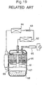
- Figs. 19 and 20 show a configuration of conventional air-conditioner and a block chart of the control unit.
- the parts are: compressor 61 containing motor 66 and compressor unit 69 which are designed to be contained inside a sealed container 67.
- Other parts are: condenser 62; decompressor 63; and evaporator 64.
- the compressor 61 is connected with the other parts to form a loop to comprise a well-known refrigerating cycle. When the compressor is not rotating, the lubricant 68 resides at an inner bottom of the compressor 61, and most part of the refrigerant are melted to the lubricant.
- Control unit 65 controls the operation of the compressor 61 and is equipped with the followings: frequency conversion circuit 65a; frequency command circuit 65b; timer circuit 65c which controls the frequency command circuit 65b; and load detection circuit 65d which detects loads on the air-conditioner. 70 is operating switch.
- the timer circuit 65c is activated after a fixed time t has lapsed, and the frequency command circuit 65b will be controlled by the load detection circuit 65d.
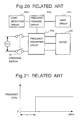
- Fig. 21 shows, when the output from the frequency command circuit 65b changes, the frequency output from the frequency conversion circuit 65a will change from 0 c/s to a certain frequency (e.g. frequency in which the motor 66 starts), then the motor 66 will starts rotation and outputs high pressure gas from the compressor 61.
- a certain frequency e.g. frequency in which the motor 66 starts
- the motor 66 will starts rotation and outputs high pressure gas from the compressor 61.
- the refrigerant that are melted into the lubricant 68 should be small, therefore, foaming of the lubricant 68 will not occur, and only the refrigerant gas is output from the compressor 61.
- the frequency output is set to 0 c/s, however, it is also possible to apply a low frequency to cause zero or small number of rotations of the motor 66.
- a frequency command circuit 65b by the load detection circuit 65d is determined using a timer, but it can also be done by temperature reading of the compressor 61.
- frequency is set to either zero or to a lower frequency so that the rotation of compressor is stopped or reduced.
- the compressor is heated up to evaporate the refrigerant melted into the lubricant.
- the compressor is designed to rotate after the evaporation that it possesses a number of advantages as: prevention of burning of each abrasive part caused by the shortage of lubricant; and no extra parts are needed such as heater and cables for the heater.
- EP 0 537512 A2 relates to a device for controlling a three-phase asynchronous motor powered by a DC source via an inverter.
- the voltage value of the DC supply is detected by a voltage sensor and a microprocessor unit decreases or increases the frequency of the inverter output in accordance with that voltage value.
- US 4 724 680 discloses a device according to the preamble of claim 1.
- the invention provides a control unit of a refrigerating machine as set out in Claim 1.
- Fig. 1 shows configuration of the compressor for embodiment 1, illustrating the following parts: AC (alternate current) power 1; converter 2 having rectifier diode; smoothing condenser 3; inverter 4 having inverter element; compressor 5 having a motor; driving circuit 7 that drives the inverter element of the inverter 4; current detection circuit 10 which detects current of the compressor; and microprocessor (start-up control unit) 9.
- AC alternate current
- converter 2 having rectifier diode
- smoothing condenser 3 smoothing condenser 3
- inverter 4 having inverter element
- compressor 5 having a motor
- driving circuit 7 that drives the inverter element of the inverter 4
- current detection circuit 10 which detects current of the compressor
- microprocessor start-up control unit
- the microporcessor 9 converts current of the compressor detected by the current detection circuit 10, from analog into digital signal. Based on a result of the conversion, the microprocessor controls the driving circuit of inverter element.
- the microprocessor 9 is a microcomputer (start-up control circuit) having a function of software to control the start-up.
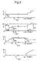
- Fig. 2 shows time charts on the start-up of compressor according to the embodiment 1.
- the horizontal axis of a, b, c and d on the charts indicate time lapsed; and the vertical axis of a, b, c and d correspond to frequency output of inverter, voltage output of inverter, input current of compressor, and rotation of the motor respectively.
- a setup current level IMO is the value of current regarded sufficient to start the motor rotation.
- fs an initial setup value of frequency as frequency output of inverter
- VS1 an initial setup values of voltage VS1 as voltage output of inverter
- the current detection circuit 10 detects input current IM in locked compressor for every ⁇ t.
- the detected input current IM exceeds setup current level of IMO at time t1, which is a current level required to start the motor.
- the control unit increases the voltage output VS1 by ⁇ VS.
- the reason for the level-up of voltage output VS1 by ⁇ VS is to obtain a minimum possible input current IM that exceeds the setup current level IMO. This is an attempt to start the motor in minimum possible electricity to conserve energy, also prevents excess current flow.
- the voltage output of the inverter should stop increasing, and should maintain the voltage at that level. For example, after the value of the input current IM has exceeded the setup current level IMO which is a sufficient level to start the motor, at time t2 after ⁇ t has lapsed from time t1, stop increasing the voltage output of inverter to maintain it unchanged.
- the motor of compressor heats up, and the viscosity of lubricant decreases by the increased temperature.
- the compressor starts to rotate, and the input current IM, which is detected by the current detection circuit 10, reduces to below setup current level IMO at time t3.
- the frequency output and voltage output of inverter are increased to control the rotation (frequency) of the compressor depending on loads.
- the current detection circuit 10 valuates the completion time of heating to pour out the resting refrigerant, and it is geared to conserve energy.
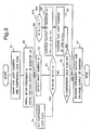
- Fig. 3 shows a control flow chart at start-up.
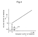
- Fig. 4 is a graph on the start-up characteristic of voltage output of inverter, showing the relation of: voltage output of inverter/frequency output of inverter (V/f).
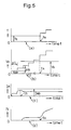
- Fig. 5 is time charts at normal start-up.
- the start-up control circuit 9 clears the counter and the lock flag based on starting signal from the compressor.
- “lock” of the compressor is, it is a situation when the motor of the compressor is not rotating.
- the lock flag is a flag that indicates that the compressor is not rotating even if there's sufficient electricity running to start the compressor.
- step 2 the compressor is started at the initial setup value, that is, as explained previously, the compressor starts at VS1/fs (voltage output of inverter/frequency output of inverter).
- step 3 the frequency output fs is maintained, and detect the input current IM after ⁇ t.
- step 4 valuate whether or not if the detected input current IM had exceeded the setup current level IMO.
- the setup current level IMO is a level of the current required to switch the compressor from the locking to the rotating mode. That is, it is the level of current required to start a rotation of the motor of compressor.
- the setup current level IMO can be used to indicate abnormality in a motor, if the motor does not rotate even after the current has reached the excess level.
- step 5 which sets the lock flag to maintain the situation
- step 6 which is a step to valuate whether lock flag is being set or not.
- step 6 the lock flag is checked.
- n is a counter number.
- step 9 for every increase in the loop counter by 1, the voltage output of inverter VS1 is raised by ⁇ VS only. That is, the voltage output of inverter Vn is VS1+(n) ⁇ VS.
- Step 10 valuates VS1+(n) ⁇ VS whether it has reached previously set driving voltage Vs shown in Fig. 4. If it has, it is functioning normally and will go to step 7. After that, operation of compressor is controlled by the voltage output and the frequency output of inverter depending on loads. If VS1+(n) ⁇ VS has not reached the previously set driving voltage Vs, it will go to step 3. After that it is a repetition from step 3 to step 10.
- step 4 when the detected input current IM has been valuated to exceed the value of setup current level IMO (time t3 of c in Fig. 2), go to step 5.
- the detected input current IM exceeding the value of setup current level IMO is, the motor is unable to rotate due to low temperature and abundant amount of resting refrigerant.
- step 3 to step 10 When the motor begins to rotate during the repetition of step 3 to step 10, this means that the motor has started normally without the input current IM having to exceed the setup current level IMO.
- Fig. 5 shows, when the motor starts to rotate at time t5, the input current IM remains low.
- step 3 to step 10 continues to repeat in this situation, Vn>Vs occurs at time t6 as shown in Fig. 5.
- the voltage output of inverter Vn equals the previously set driving voltage Vs as described previously, it will go from step 10 to step 7, and the operation of compressor is controlled by the voltage output of inverter and the frequency output of inverter depending on loads. Therefore, if went from step 10 to step 7, it is the case of normal function without the input current IM having to exceed the setup current level IMO.
- step 5 If the motor failed to rotate as normal the lock flag is set at step 5. Then returns to step 3 as done so in Fig. 2, without increasing the voltage output.
- the current input IM is detected in step 3 and again in step 4 repeats the step of valuation whether or not if the detected input current IM exceeded the setup current level IMO.
- the detected input current IM is below the setup current level IMO (time t4 of c in Fig. 2), that means the motor in locking mode is heated up by running of electricity and the temperature of lubricant is increased which decreases the viscosity causing the decline in fricitional resistance of each abrasive part to begin the rotation of compressor, and eventually decreasing the input current IM.
- step 6 When the input current IM is valuated to be below the setup current level IMO, go to step 6, and in this step, the lock flag is checked. As the lock flag has been set, it goes to step 7 where compressor operation for the voltage output of inverter and the frequency output of inverter are controlled depending on loads. As such, heating completes when the current has been detected and the motor starts to rotate. In other words, the heating can be done in the exact time needed. This is quite different from the conventional method where heating time was exactly for 3 minutes or for a fixed time period t.
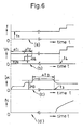
- the voltage VS1 of the initial frequency fs is increased for every ⁇ t, however, it can also be for a predetermined time. For example, as Fig. 6 shows, if set the time to be longer to start with and then shorter next ( ⁇ t1> ⁇ t2), time ⁇ t3 can be made shorter, which is the time period of excess current flow at above the setup current level IMO to raise the coil temperature. Therefore, the resting refrigerant will be poured out under the most safe condition and the credibility of refrigerating machine increases.
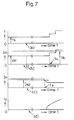
- Fig. 7 shows, when the voltage VS1 for the initial frequency fs is below the driving voltage Vs, there's no problem for the initial input current IM being in excess to the setup current level IMO. In such a case, as with the flow chart shown in Fig. 3, the steps from 8 to 10 are skipped, and the start-up is controlled within step 1 to step 7.
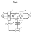
- Fig. 8 shows a configuration for the embodiment 2.
- 6 is DC-line current detection circuit that protects excess current of DC-line inverter element.
- the detailed explanation of all other parts are as explained in the embodiment 1.
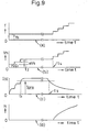
- Fig. 9 is time charts for the start-up of compressor for the embodiment 2.
- the horizontal axis of a, b, c and d on the charts indicate time lapsed; and the vertical axis of a, b, c and d correspond to frequency output of inverter, voltage output of inverter, DC-line current and rotation of compressor respectively.
- outputs are made to the compressor.
- the initial setup value of frequency fs as frequency output of inverter, and the initial setup value for voltage VS1 as voltage output of inverter.
- the DC-line current detection circuit 6 detects DC-line current IDC from the compressor in locking mode for every ⁇ t. For every ⁇ t the voltage output VS1 is raised by ⁇ VS until time t1. The detected DC-line current IDC exceeds a setup level value of DC-line current IDCO at time t1. The level value of DC-line current IDCO is a required level to move from the locking mode to the rotating mode.
- the motor of compressor heats up which can increase the temperature of lubricant, causing decline in viscosity to cause decrease in the frictional resistance of abrasive parts. Then the compressor begins to rotate and the DC-line current IDC decreases to below the setup level value of DC-line current IDCO at time t3. At time t4 after time ⁇ t has lapsed, as a and b of Fig. 9 shows, the frequency output of inverter and the voltage output of inverter are increased which will control a number of rotations (frequency) of the compressor depending on loads.
- DC-line current detection circuit 6 valuates driving based on detection from DC-line current of inverter. A measure of valuation had simply been substituted from the input current for compressor IM to the DC-line current for inverter IDC. All other mechanisms are as explained in the embodiment 1, therefore, the explanation on operational flow is omitted.
- Fig. 10 shows a configuration of the embodiment 3.
- 8 is a power-supplied input current detection circuit that detects power-supplied input current.
- Other parts of the configuration are as explained in the embodiment 1, therefore, the detailed explanation is omitted.
- Fig. 11 is time charts on the start-up of compressor for the embodiment 3.
- the horizontal axis of a, b, c and d on the charts indicate time and the vertical axis of a, b, c and d correspond to frequency output of inverter, voltage output of inverter, power-supplied input current and a number of rotations of compressor respectively.
- the power-supplied input current detection circuit 8 valuates driving of the compressor based on power-supplied input current IAC. A measure of valuation had simply been substituted from the input current for compressor IM to the power-supplied input current IAC.
- Fig. 11 shows, on start-up, outputs are made to the compressor.
- the frequency output of inverter the initial setup value of frequency fs
- voltage output of inverter the initial setup value of voltage VS1.
- the frequency output fs and the initial setup value for voltage VS1 are maintained until the compressor starts to rotate. Maintaining the situation, detect power-supplied input current IAC, and when the detected power-supplied current IAC is exceeding the previously set level value of power-supplied input setup current IACO, maintain this situation.
- the compressor rotates and the power-supplied current IAC decreases to below the power-supplied input setup current IACO at time t1.
- time t2 after time ⁇ t has lasped the frequency output of inverter and the voltage output of inverter are increased.
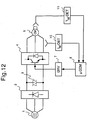
- Fig. 12 shows a configuration of the control unit for embodiment 4.
- 11 is a temperature sensor which measures the motor temperature in the compressor. All other parts in this configuration are as described in the embodiment 1, therefore, the detailed explanation is omitted.
- Fig. 13 is time charts on the start-up of compressor for the embodiment 4.
- the horizontal axis of a, b, c and d on the charts indicate time and the vertical axis of a, b, c and d correspond to the frequency output of inverter, and the motor temperature of compressor respectively.
- Fig. 13 shows a case when the motor temperature TM, which is detected by the temperature sensor 11, had become greater than the highest setup temperature TMO before the compressor rotation.
- Fig. 2 shows, on start-up, outputs are made to the compressor. As the frequency output of inverter the initial setup value of frequency fs, and as voltage output of inverter the initial setup value of voltage VS1. On starting, the frequency output fs and the initial setup value for voltage VS1 are maintained until the compressor starts to rotate.
- the current detection circuit 10 detects the input current of compressor IM in the locking mode for every ⁇ t, and until the detected input current for compressor IM exceeds the previously set value of setup current level IMO at time t1, the voltage output VS1 at the control unit is increased by ⁇ VS for every ⁇ t.
- the motor inside the compressor heats up which causes the temperature of lubricant to increase, leading to a decrease in its viscosity, which in turn will causes decline in the frictional resistance of abrasive parts and the compressor begins to rotate.
- the detected input current of compressor IM decreases to below the setup current level IMO after time ⁇ t at time t3
- the voltage output of inverter and the frequency output of inverter are increased at time t4 as shown in a and b of Fig. 2, this can control a number of rotations (frequency) of the compressor depending on loads.
- a control method one is to block inverter output as shown in time t1 of Fig. 13.
- a control method three is, when the motor temperature measured by the temperature sensor 11 is greater than the highest set temperature, the compressor is assumed that it has an adequate heat.
- the voltage output and frequency output of inverter are increased to control the rotation (frequency) of compressor, depending on loads.
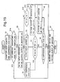
- Fig. 14 is an operational flow chart on controlled start-up for the embodiment 4.
- Fig. 14 shows in step 11 the start-up control unit 9 clears the lock flag and the counter based on the starting signal of compressor in order to set initial values of the software (S/W) loop counter and the compressor lock flag.
- step 12 the compressor starts at the initial setup value, that is, as described previously, the compressor starts at; VS1/fs (voltage output of inverter/frequency output of inverter).
- step 13 under the maintained frequency output fs, the input current for compressor IM is detected after time A t.
- Step 14 valuates whether the detected input current of compressor IM had exceeded or not the setup current level IMO.
- step 15 From the initial valuation result where lock flag is unset and if IM>IMO, go to step 15, and if IM ⁇ IMO, then go to step 17 to determine if lock flag is set or unset.
- the initial voltage output VS1 is set so the initial input current for compressor IM is always below the setup current level IMO, therefore, goes to step 17.
- step 17 the lock flag is unset so proceed to step 18 and see if the motor temperature of the compressor is greater or smaller than the highest set temperature. If the temperature is greater than the highest set temperature, the lubricant is sufficiently warm inside the compressor, so proceed to step 22, and the voltage output and frequency output of inverter are increased to control the rotation (frequency) depending on loads.
- step 19 to increase the loop counter by one, then proceed to step 20.
- step 20 for every increase in the loop counter by one, increase the voltage output of inverter VS1 by ⁇ VS. That is, voltage output of inverter Vn is VS1+(n) ⁇ VS.
- n is the counter number.
- step 21 VS1+(n) ⁇ VS valuates whether or not if it has reached the previously set driving voltage Vs. If it has, go to step 22 to control the operation for the voltage output of inverter and frequency output of inverter of compressor depending on loads.
- step 13 If VS1+(n) ⁇ VS has not reached previously set driving voltage Vs, go to step 13 to repeat steps 13 to step 20.
- step 22 When the voltage output of inverter Vn became the same value as the previously set driving voltage Vs during the repetition, as described before, go to step 22 to control the operation of the voltage output of inverter and frequency output of inverter of compressor depending on loads.
- step 14 While repeating the steps 13 to 20, if the input current of compressor IM detected in step 14 exceeded the setup current level IMO, go to step 15.
- the motor temperature of compressor is measured to see if the temperature is over or under the highest set temperature. From a result of the measurement, if it is over the highest set temperature, the lubricant inside the compressor is sufficiently warm meaning there's no resting refrigerant, so proceed to step 22 to increase the frequency output of inverter and the output voltage of inverter, and control a number of rotations (frequency) of compressor depending on loads.
- step 16 when the motor temperature is below the highest set temperature, the voltage output remains intact and go to step 16 to set the lock flag to maintain the situation then returns to step 13 to re-detect the input current of compressor IM after time ⁇ t.
- step 14 repeat the valuation if the input current IM has exceeded the setup current level IMO.
- the voltage VS1 of the initial frequency fs was increased for every ⁇ t but it can also be for a fixed time. For instance, if set the time so that it is longer in duration to start with, followed by shorter duration, so that time period between excess current flow can be made shorter when raising coil temperature that this is much a safer way to pour out the resting refrigerant.
- the temperature sensor 11 measures the motor temperature of compressor to valuate whether or not if the measured temperature is over the highest set temperature.
- the temperature sensor 11 can be set to measure the temperature of lubricant that is appropriate as the motor temperature of compressor, or as a shell temperature of compressor, and either one of these can be the basis of valuation to valuate if the motor temperature had become over the highest set temperature.
- step 15 or 18 can use a software program for counting a period of time between power off to power on mode of the compressor. That is, for step 15 or 18, if the period of time between the power off to power on of the compressor is below the pre-setted time, the compressor is still warm, and can proceed to step 22.
- step 1a is inserted between step 1 and 2.
- the temperature characteristic value that corresponds to the motor temperature of the compressor e.g. temperature of lubricant in the compressor
- step 2 If the temperature characteristic value is under the highest set temperature, go to step 2, so that if the temperature of lubricant is low, that is, a temperature when the amount of resting refrigerant is large inside the compressor, the refrigerant must be heated.
- the temperature of refrigerant is high, that is, a temperature when the amount of resting refrigernat is low, the unnecessary heating will not take place. By doing so it helps to prevent the deteoriation of lubricant to provide the control unit of refrigerating machine that are economically sound and high in credibility.
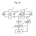
- Fig. 16 shows a configuration of the embodiment 5.
- Fig. 17 is time charts of the start-up control unit for the embodiment 5.
- excess current protection circuit 12 is set in place. The excess current protection circuit 12 hold the protection level value of excess current IMC.
- the excess current protection circuit 12 blocks the voltage output of inverter, and the result of the blockage is indicated at display unit 13.
- the excess current protection circuit 12 can also be installed to embodiments 2 to 4 (not illustrated). Instead of the excess current protection circuit 12, can design something else that achieves similar function as the excess current protection circuit 12 at the start-up control circuit 9.
Landscapes
- Engineering & Computer Science (AREA)
- Power Engineering (AREA)
- Air Conditioning Control Device (AREA)
- Compressor (AREA)
- Control Of Positive-Displacement Pumps (AREA)
- Control Of Ac Motors In General (AREA)
Description
- The invention relates to a control unit of a compressor controlling the start-up operation for refrigerating machines such as air-conditioners and refrigerators.
- Conventional configuration and operation of the start-up control unit for refrigerating machines disclosed in the Japanese examined patent publication No. hei6-15864 (JP 61272480 A) are explained using Fig. 18.
- For conventional compressor incorporated in refrigerating cycle machines, because a large amount of electrical current is required to start an operation of the compressor at a low temperature, some of the compressors tended to fail on start-up due to an activation of "protection circuit" caused from a running of excess current.
- That is, for the conventional compressor at the low temperature, a viscosity of lubricant inside the compressor increases that the fluidity decreases. Not only this results in viscose and frictional drags at abrasive and rotational parts of the compressor, but also allows electrical current to flow easily due to a reduced electrical resistance in the motor coil under low temperature. This being the case, once the start-up failure occurs, even after a recovery from the protection circuit and then attempted to re-start, the compressor is likely to fail again. When this is repeated several times, some of the refrigerating cycle machines may take this as malfunction which can lead to a problem of shutdown of the whole machine.
- Even though it will not come to the point of shutdown of the whole machine, there are situations when the machine cannot function for some length of time that this will leads to a danger of losing credibility of the refrigerating machine itself by such forceful start-ups.
- Fig. 18 has taken into consideration such situations, aiming to provide a start-up control unit of refrigerating cycle machines that has a heat-up function for some period of time before re-starting the machine when the failing occurs.
- As Fig. 18 is showing, the parts are as follows:
compressor 81; pre-heatingunit 82;exterior unit 83;central control unit 84;main inverter circuit 85;converter 86;inverter 87; excesscurrent sensor 88 that detects excess current of thecompressor 81; excesscurrent detection circuit 90; andinterior unit 91. - Next, operation is explained. Upon start-up, when the excess
current sensor 88 in themain inverter circuit 85 has detected excess current, the detected signal is transmitted to thecentral processing unit 84 via the excesscurrent detection circuit 90. At thecentral processing unit 84, excess current protection circuit is activated, and this stops the start-up of thecompressor 81. Simultaneously, frequency output control circuit of inverter at thecentral processing unit 84 activates thepre-heating unit 82 to heat up thecompressor 81. Using the heat from a motor of thecompressor 81, a refrigerant resting inside the lubricant is poured out by heating for about 3 minutes. The refrigerant resting inside the lubricant is a medium that was liquified inside the compressor. Under a normal condition the refrigerant is carbureted to be used by thecompressor 81 during the refrigerating cycle. However, due to a decreased temperature from the stopped compressor, the carbureted refrigerant is liquified, then become mixed with the lubricant. The liquified refrigerant inside the compressor is termed "resting refrigerant". An amount of liquified resting refrigerant is called "amount of resting refrigerant". The refrigerant that is carbureted due to rise in compressor temperature is used in the refrigerating cycle. The reason for pre-heating the compressor is to carburete the resting refrigerant. After pre-heating for 3 minutes, thecentral processing unit 84 re-activates thecompressor 81. Atemperature sensor 92 can be attached to thepre-heating unit 82, and the temperature reading can be transmitted to thecentral processing unit 84 for control. - Operation of another control unit of the compressor in conventional air-conditioners is disclosed in the Japanese unexamined utility model publication No. sho56-134561 (JP 56134561 U) will be explained using Fig. 19 and 20. Conventionally, when starting the air-conditioner, foaming reaction occurs from the refrigerant being mixed with the lubricant inside the compressor. The foaming of lubricant is caused by an increase in the temperature of compressor, and the lubricant is output from the compressor during refrigerating cycle. This result in a shortage of the lubricant, which causes lots of incident of burning of abrasive parts of the compressor.
- To improve from such incidents, heater was attached to a sealed container of the compressor as shown in Figure 18; then the compressor was heated to prevent a melting of the refrigerant into the lubricant. However, such configuration needs a power supply for the heater. The disadvantages were wasting of power, and an addition of extra parts as heater and cables for the heater.
- Figs. 19 and 20 show a configuration of conventional air-conditioner and a block chart of the control unit.
- The parts are:
compressor 61 containingmotor 66 andcompressor unit 69 which are designed to be contained inside a sealedcontainer 67. Other parts are:condenser 62;decompressor 63; andevaporator 64. Thecompressor 61 is connected with the other parts to form a loop to comprise a well-known refrigerating cycle. When the compressor is not rotating, thelubricant 68 resides at an inner bottom of thecompressor 61, and most part of the refrigerant are melted to the lubricant.Control unit 65 controls the operation of thecompressor 61 and is equipped with the followings:frequency conversion circuit 65a;frequency command circuit 65b;timer circuit 65c which controls thefrequency command circuit 65b; andload detection circuit 65d which detects loads on the air-conditioner. 70 is operating switch. - The operation of air-conditioner for above-mentioned configuration is explained below.
- First of all, turn on the
operating switch 70, and an output command of frequency 0 c/s (cycles/second) is generated to thefrequency conversion circuit 65a from thefrequency command circuit 65b. The frequency output of 0 c/s from thefrequency conversion circuit 65a is made, or in other words, a DC (direct current) is supplied to themotor 66 of thecompressor 61. Themotor 66 heats up without rotating when the DC flows through. The heat from themotor 66 will heat-up the sealedcontainer 67 and thelubricant 68. Due to this the refrigerant that were melted into thelubricant 68 become carbureted and will be separated from thelubricant 68. - The
timer circuit 65c is activated after a fixed time t has lapsed, and thefrequency command circuit 65b will be controlled by theload detection circuit 65d. As Fig. 21 shows, when the output from thefrequency command circuit 65b changes, the frequency output from thefrequency conversion circuit 65a will change from 0 c/s to a certain frequency (e.g. frequency in which themotor 66 starts), then themotor 66 will starts rotation and outputs high pressure gas from thecompressor 61. This being the case, the refrigerant that are melted into thelubricant 68 should be small, therefore, foaming of thelubricant 68 will not occur, and only the refrigerant gas is output from thecompressor 61. - Therefore, when the operation of
compressor 61 starts, the burning of each abrasive part of thecompressor 61 caused by the shortage oflubricant 68 can be prevented. Also, extra electricity for heating is not necessary. - The frequency output is set to 0 c/s, however, it is also possible to apply a low frequency to cause zero or small number of rotations of the
motor 66. Apart from the two types of frequency in the frequency conversion control, can also design a configuration which is controlled by a gradual increase in the frequency. In addition, a period of time for controlling thefrequency command circuit 65b by theload detection circuit 65d is determined using a timer, but it can also be done by temperature reading of thecompressor 61. - For the conventional operation control unit of air-conditioner, upon starting the compressor, frequency is set to either zero or to a lower frequency so that the rotation of compressor is stopped or reduced. From a heat generated from the coil of motor, the compressor is heated up to evaporate the refrigerant melted into the lubricant. The compressor is designed to rotate after the evaporation that it possesses a number of advantages as: prevention of burning of each abrasive part caused by the shortage of lubricant; and no extra parts are needed such as heater and cables for the heater.
- As explained above, for the start-up control unit of refrigerating machine in Figure 18, after detecting excess current of compressor the
compressor 81 is turned off for a fixed amount of time (3 minutes) for heating, and then tries to re-start. Similarly, for the operating control unit of refrigerating machine in Figures 19 and 20, the compressor starts after heating the compressor for a fixed time t using the heat generated from the coil of motor. As can be seen in both cases of related art, the start-ups are controlled without any consideration of the amount of resting refrigerant inside the compressors. Therefore, the problem is: it does not take into account the fact that an immediate re-starting is possible. That is, even in a situation when the resting refrigerant requires only a short heating time (i.e. case when the amount of resting refrigerant is low), and the excess current has flown, it must always stop and wait for a fixed amount of time (3 minutes or time t) before re-starting. When the amount of resting refrigerant is large, on contrary, the 3 minutes or time t may not be enough heating time but it is set to re-start in that period, resulting in consumption of extra energy, in addition, too great a rise in temperature of the motor of compressor can cause various troubles (e.g. burning of abrasive parts from rise in lubricant temperature). - Also, various incidents can result from foaming of the lubricant, making re-starting even more difficult.
-
EP 0 537512 A2 relates to a device for controlling a three-phase asynchronous motor powered by a DC source via an inverter. The voltage value of the DC supply is detected by a voltage sensor and a microprocessor unit decreases or increases the frequency of the inverter output in accordance with that voltage value. - US 4 724 680 discloses a device according to the preamble of
claim 1. - In view of the foregoing, the invention provides a control unit of a refrigerating machine as set out in
Claim 1. - Preferred features of the invention are set out in
Claims 2 to 8. - Further scope of applicability of the present invention will become apparent from the detailed description given hereinafter. However, it should be understood that the detailed description and specific examples, while indicating preferred embodiments of the invention, are given by way of illustration only, since various changes and modifications within the scope of the invention will become apparent to those skilled in the art from this detailed description.
- The present invention will become more fully understood from the detailed description given hereinbelow and the accompanying drawings which are given by way of illustration only, and thus do not limit of the present invention, and wherein:
- Fig. 1 shows the configuration of control unit of
refrigerating machine of
embodiment 1; - Fig. 2 shows the time charts of control unit of
refrigerating machine of
embodiment 1; - Fig. 3 shows the operational flow chart of
control unit of refrigerating machine of
embodiment 1; - Fig. 4 shows the characteristic diagram of start-up
inverter output V/F of control unit of refrigerating
machine of
embodiment 1; - Fig. 5 shows the time chart of control unit of
refrigerating machine of
embodiment 1; - Fig. 6 shows the time chart of control unit of
refrigerating machine of
embodiment 1; - Fig. 7 shows the time chart of control unit of
refrigerating machine of
embodiment 1; - Fig. 8 shows the configuration of refrigerating
machine for
embodiment 2; - Fig. 9 shows the time charts of control unit of
refrigerating machine for
embodiment 2; - Fig. 10 shows the configuration of refrigerating
machine for
embodiment 3; - Fig. 11 shows the time charts of control unit of
refrigerating machine for
embodiment 3; - Fig. 12 shows the configuration of control unit
of refrigerating machine for
embodiment 4; - Fig. 13 shows the time charts of control unit of
refrigerating machine for
embodiment 4; - Fig. 14 shows the operational flow chart of
control unit of refrigerating machine for
embodiment 4; - Fig. 15 shows the operational flow chart of
control unit of refrigerating machine for
embodiment 4; - Fig. 16 shows the configuration of control unit
of refrigerating machine for
embodiment 5; - Fig. 17 shows the time charts of control unit of
refrigerating machine for
embodiment 5; - Fig. 18 shows the operational flow chart of control unit of the prior art;
- Fig. 19 shows the refrigerating cycle of air-conditioner from further prior art provided with operating control unit;
- Fig. 20 shows the configuration of operating control unit for air-conditioner of Figure 19; and
- Fig. 21 shows the characteristic of frequency output of operating control unit for air-conditioner of Figures 19 and 20.
-
- Reference will now be made in detail to the present preferred embodiments of the invention, examples of which are illustrated in the accompanying drawings, wherein like reference numerals indicate like elements through out the several views.
- Fig. 1 shows configuration of the compressor for
embodiment 1, illustrating the following parts: AC (alternate current)power 1;converter 2 having rectifier diode; smoothingcondenser 3;inverter 4 having inverter element;compressor 5 having a motor; drivingcircuit 7 that drives the inverter element of theinverter 4;current detection circuit 10 which detects current of the compressor; and microprocessor (start-up control unit) 9. - The
microporcessor 9 converts current of the compressor detected by thecurrent detection circuit 10, from analog into digital signal. Based on a result of the conversion, the microprocessor controls the driving circuit of inverter element. Themicroprocessor 9 is a microcomputer (start-up control circuit) having a function of software to control the start-up. - Fig. 2 shows time charts on the start-up of compressor according to the
embodiment 1. The horizontal axis of a, b, c and d on the charts indicate time lapsed; and the vertical axis of a, b, c and d correspond to frequency output of inverter, voltage output of inverter, input current of compressor, and rotation of the motor respectively. In Fig. 2, a setup current level IMO is the value of current regarded sufficient to start the motor rotation. - Next, operation is explained.
- To begin with, as the Fig. 2 shows, at start-up, following outputs are made to the compressor: fs, an initial setup value of frequency as frequency output of inverter; and VS1, an initial setup values of voltage VS1 as voltage output of inverter. At the starting time, the frequency output fs is maintained and unchanged until the compressor starts.
- Under the maintained frequency output fs, the
current detection circuit 10 detects input current IM in locked compressor for every Δt. The detected input current IM exceeds setup current level of IMO at time t1, which is a current level required to start the motor. From time t1, for every Δt, the control unit increases the voltage output VS1 by ΔVS. The reason for the level-up of voltage output VS1 by ΔVS is to obtain a minimum possible input current IM that exceeds the setup current level IMO. This is an attempt to start the motor in minimum possible electricity to conserve energy, also prevents excess current flow. - When the input current IM exceeds the setup current level IMO, the voltage output of the inverter should stop increasing, and should maintain the voltage at that level. For example, after the value of the input current IM has exceeded the setup current level IMO which is a sufficient level to start the motor, at time t2 after Δt has lapsed from time t1, stop increasing the voltage output of inverter to maintain it unchanged.
- By supplying electricity in this situation, the motor of compressor heats up, and the viscosity of lubricant decreases by the increased temperature. As the frictional resistance of each abrasive part decreases, the compressor starts to rotate, and the input current IM, which is detected by the
current detection circuit 10, reduces to below setup current level IMO at time t3. After time Δt has lapsed at time t4, as a and b of Fig. 2 are showing, the frequency output and voltage output of inverter are increased to control the rotation (frequency) of the compressor depending on loads. What is meant by detecting decreased input current IM from thecurrent detection circuit 10 is, the compressor has begun to rotate. Therefore, there's no extra requirement to heat up the motor with electricity. According to this invention, thecurrent detection circuit 10 valuates the completion time of heating to pour out the resting refrigerant, and it is geared to conserve energy. - Followings are detailed explanations, referring to Figs. 3, 4 and 5, on the start-up control operation.
- Fig. 3 shows a control flow chart at start-up. Fig. 4 is a graph on the start-up characteristic of voltage output of inverter, showing the relation of: voltage output of inverter/frequency output of inverter (V/f). Fig. 5 is time charts at normal start-up.
- To start with
step 1, as Fig. 3 shows, in order to set the initial values of software (S/W) loop counter and compressor lock flag, the start-upcontrol circuit 9 clears the counter and the lock flag based on starting signal from the compressor. What is meant by "lock" of the compressor is, it is a situation when the motor of the compressor is not rotating. The lock flag is a flag that indicates that the compressor is not rotating even if there's sufficient electricity running to start the compressor. - In
step 2, the compressor is started at the initial setup value, that is, as explained previously, the compressor starts at VS1/fs (voltage output of inverter/frequency output of inverter). - In
step 3, the frequency output fs is maintained, and detect the input current IM after Δt. - In
step 4, valuate whether or not if the detected input current IM had exceeded the setup current level IMO. Here, the setup current level IMO is a level of the current required to switch the compressor from the locking to the rotating mode. That is, it is the level of current required to start a rotation of the motor of compressor. Also, the setup current level IMO can be used to indicate abnormality in a motor, if the motor does not rotate even after the current has reached the excess level. - Based on the results of valuation, in an excess case (IM>IMO), the voltage output will not be increased and advances to step 5 which sets the lock flag to maintain the situation, and for a case when not in excess (IM≦ IMO), proceed to step 6 which is a step to valuate whether lock flag is being set or not.
- Previously mentioned initial voltage output VS1 is set at low level to start with so initially, the input current IM is always below the setup current level IMO, therefore, the first valuation always leads to step 6.
- In
step 6, the lock flag is checked. When the lock flag is not set yet it advances to step 8. The loop counter n is increased by 1 (n+1=n), and advances to next step. - Numeral n is a counter number.
- In
step 9, for every increase in the loop counter by 1, the voltage output of inverter VS1 is raised by ΔVS only. That is, the voltage output of inverter Vn is VS1+(n)ΔVS. -
Step 10 valuates VS1+(n)ΔVS whether it has reached previously set driving voltage Vs shown in Fig. 4. If it has, it is functioning normally and will go tostep 7. After that, operation of compressor is controlled by the voltage output and the frequency output of inverter depending on loads. If VS1+(n)ΔVS has not reached the previously set driving voltage Vs, it will go tostep 3. After that it is a repetition fromstep 3 to step 10. - During the repetition of
step 3 to step 10, atstep 4 when the detected input current IM has been valuated to exceed the value of setup current level IMO (time t3 of c in Fig. 2), go tostep 5. What is meant by the detected input current IM exceeding the value of setup current level IMO is, the motor is unable to rotate due to low temperature and abundant amount of resting refrigerant. - When the motor begins to rotate during the repetition of
step 3 to step 10, this means that the motor has started normally without the input current IM having to exceed the setup current level IMO. For example, as Fig. 5 shows, when the motor starts to rotate at time t5, the input current IM remains low. And whenstep 3 to step 10 continues to repeat in this situation, Vn>Vs occurs at time t6 as shown in Fig. 5. When the voltage output of inverter Vn equals the previously set driving voltage Vs as described previously, it will go fromstep 10 to step 7, and the operation of compressor is controlled by the voltage output of inverter and the frequency output of inverter depending on loads. Therefore, if went fromstep 10 to step 7, it is the case of normal function without the input current IM having to exceed the setup current level IMO. - If the motor failed to rotate as normal the lock flag is set at
step 5. Then returns to step 3 as done so in Fig. 2, without increasing the voltage output. After time Δt, the current input IM is detected instep 3 and again instep 4 repeats the step of valuation whether or not if the detected input current IM exceeded the setup current level IMO. During the process of repetition, when the detected input current IM is below the setup current level IMO (time t4 of c in Fig. 2), that means the motor in locking mode is heated up by running of electricity and the temperature of lubricant is increased which decreases the viscosity causing the decline in fricitional resistance of each abrasive part to begin the rotation of compressor, and eventually decreasing the input current IM. When the input current IM is valuated to be below the setup current level IMO, go tostep 6, and in this step, the lock flag is checked. As the lock flag has been set, it goes to step 7 where compressor operation for the voltage output of inverter and the frequency output of inverter are controlled depending on loads. As such, heating completes when the current has been detected and the motor starts to rotate. In other words, the heating can be done in the exact time needed. This is quite different from the conventional method where heating time was exactly for 3 minutes or for a fixed time period t. - As explained above, the voltage VS1 of the initial frequency fs is increased for every Δt, however, it can also be for a predetermined time. For example, as Fig. 6 shows, if set the time to be longer to start with and then shorter next (Δt1>Δt2), time Δt3 can be made shorter, which is the time period of excess current flow at above the setup current level IMO to raise the coil temperature. Therefore, the resting refrigerant will be poured out under the most safe condition and the credibility of refrigerating machine increases.
- As Fig. 7 shows, when the voltage VS1 for the initial frequency fs is below the driving voltage Vs, there's no problem for the initial input current IM being in excess to the setup current level IMO. In such a case, as with the flow chart shown in Fig. 3, the steps from 8 to 10 are skipped, and the start-up is controlled within
step 1 to step 7. - The
embodiment 2 of this invention is explained below. - Fig. 8 shows a configuration for the
embodiment 2. In this figure, 6 is DC-line current detection circuit that protects excess current of DC-line inverter element. The detailed explanation of all other parts are as explained in theembodiment 1. - Fig. 9 is time charts for the start-up of compressor for the
embodiment 2. The horizontal axis of a, b, c and d on the charts indicate time lapsed; and the vertical axis of a, b, c and d correspond to frequency output of inverter, voltage output of inverter, DC-line current and rotation of compressor respectively. - The operation is explained below.
- As the figure shows, outputs are made to the compressor. The initial setup value of frequency fs as frequency output of inverter, and the initial setup value for voltage VS1 as voltage output of inverter.
- On starting, the frequency output fs is maintained until the compressor is started.
- Maintaining the situation, the DC-line
current detection circuit 6 detects DC-line current IDC from the compressor in locking mode for every Δt. For every Δt the voltage output VS1 is raised by ΔVS until time t1. The detected DC-line current IDC exceeds a setup level value of DC-line current IDCO at time t1. The level value of DC-line current IDCO is a required level to move from the locking mode to the rotating mode. - After the DC-line current IDC has exceeded the level value of DC-line current IDCO, maintain the frequency output, and stop increasing the voltage output.
- By supplying electricity as maintaining the frequency output, the motor of compressor heats up which can increase the temperature of lubricant, causing decline in viscosity to cause decrease in the frictional resistance of abrasive parts. Then the compressor begins to rotate and the DC-line current IDC decreases to below the setup level value of DC-line current IDCO at time t3. At time t4 after time Δt has lapsed, as a and b of Fig. 9 shows, the frequency output of inverter and the voltage output of inverter are increased which will control a number of rotations (frequency) of the compressor depending on loads.
- That is, for
embodiment 2, in place of the current detection circuit ofembodiment 1, DC-linecurrent detection circuit 6 is used. The DC-linecurrent detection circuit 6 valuates driving based on detection from DC-line current of inverter. A measure of valuation had simply been substituted from the input current for compressor IM to the DC-line current for inverter IDC. All other mechanisms are as explained in theembodiment 1, therefore, the explanation on operational flow is omitted. - The
embodiment 3 of this invention is explained below. - Fig. 10 shows a configuration of the
embodiment 3. In the figure, 8 is a power-supplied input current detection circuit that detects power-supplied input current. Other parts of the configuration are as explained in theembodiment 1, therefore, the detailed explanation is omitted. - Fig. 11 is time charts on the start-up of compressor for the
embodiment 3. The horizontal axis of a, b, c and d on the charts indicate time and the vertical axis of a, b, c and d correspond to frequency output of inverter, voltage output of inverter, power-supplied input current and a number of rotations of compressor respectively. - For the
embodiment 3, in place of the current detection circuit for compressor of theembodiment 1 the power-supplied inputcurrent detection circuit 8 is used. The power-supplied inputcurrent detection circuit 8 valuates driving of the compressor based on power-supplied input current IAC. A measure of valuation had simply been substituted from the input current for compressor IM to the power-supplied input current IAC. - As Fig. 11 shows, on start-up, outputs are made to the compressor. As the frequency output of inverter the initial setup value of frequency fs, and as voltage output of inverter the initial setup value of voltage VS1. On starting, the frequency output fs and the initial setup value for voltage VS1 are maintained until the compressor starts to rotate. Maintaining the situation, detect power-supplied input current IAC, and when the detected power-supplied current IAC is exceeding the previously set level value of power-supplied input setup current IACO, maintain this situation. The compressor rotates and the power-supplied current IAC decreases to below the power-supplied input setup current IACO at time t1. At time t2 after time Δt has lasped the frequency output of inverter and the voltage output of inverter are increased.
- The
embodiment 4 of this invention is explained below. - Fig. 12 shows a configuration of the control unit for
embodiment 4. In the figure, 11 is a temperature sensor which measures the motor temperature in the compressor. All other parts in this configuration are as described in theembodiment 1, therefore, the detailed explanation is omitted. - Similarly, Fig. 13 is time charts on the start-up of compressor for the
embodiment 4. The horizontal axis of a, b, c and d on the charts indicate time and the vertical axis of a, b, c and d correspond to the frequency output of inverter, and the motor temperature of compressor respectively. Fig. 13 shows a case when the motor temperature TM, which is detected by thetemperature sensor 11, had become greater than the highest setup temperature TMO before the compressor rotation. - Following is the explanation of a case when the motor temperature measured by the
temperature sensor 11 that has not become greater than the highest set temperature TMO. In this case, the operation is similar to the previously described case in Fig. 2. As Fig. 2 shows, on start-up, outputs are made to the compressor. As the frequency output of inverter the initial setup value of frequency fs, and as voltage output of inverter the initial setup value of voltage VS1. On starting, the frequency output fs and the initial setup value for voltage VS1 are maintained until the compressor starts to rotate. - When the motor temperature TM measured by the
temperature sensor 11 has not reached the temperature greater than the highest set temperature TMO, which is a fixed temperature as a protection temperature of the coil in motor, thecurrent detection circuit 10 detects the input current of compressor IM in the locking mode for every Δ t, and until the detected input current for compressor IM exceeds the previously set value of setup current level IMO at time t1, the voltage output VS1 at the control unit is increased by ΔVS for every Δt. - After the input current of compressor IM has exceeded the setup current level IMO, a voltage increase for the output voltage is terminated, and the situation is maintained if the motor temperature TM measured by the temperature sensor has not reached the highest set temperature TMO.
- By supplying the electricity maintaining this situation, the motor inside the compressor heats up which causes the temperature of lubricant to increase, leading to a decrease in its viscosity, which in turn will causes decline in the frictional resistance of abrasive parts and the compressor begins to rotate. When the detected input current of compressor IM decreases to below the setup current level IMO after time Δt at time t3, the voltage output of inverter and the frequency output of inverter are increased at time t4 as shown in a and b of Fig. 2, this can control a number of rotations (frequency) of the compressor depending on loads.
- If the compressor is unable to rotate and when the motor temperature TM measured by the
temperature sensor 11 had became greater than the highest set temperature TMO, there are three controlling methods as below. - A control method one is to block inverter output as shown in time t1 of Fig. 13.
- A control method two is, following the blockage of output inverter as of the control method one, after a fixed time has lapsed from time t1 when the motor temperature had become lower than the lowest set temperature, return to the start (time t=0).
- A control method three is, when the motor temperature measured by the
temperature sensor 11 is greater than the highest set temperature, the compressor is assumed that it has an adequate heat. The voltage output and frequency output of inverter are increased to control the rotation (frequency) of compressor, depending on loads. - Next, among the previously described start-up control methods, the
control method 3 is explained in detail using Fig. 14. - Fig. 14 is an operational flow chart on controlled start-up for the
embodiment 4. - As Fig. 14 shows in
step 11 the start-upcontrol unit 9 clears the lock flag and the counter based on the starting signal of compressor in order to set initial values of the software (S/W) loop counter and the compressor lock flag. - In
step 12, the compressor starts at the initial setup value, that is, as described previously, the compressor starts at; VS1/fs (voltage output of inverter/frequency output of inverter). - In
step 13, under the maintained frequency output fs, the input current for compressor IM is detected after time A t. -
Step 14 valuates whether the detected input current of compressor IM had exceeded or not the setup current level IMO. - From the initial valuation result where lock flag is unset and if IM>IMO, go to step 15, and if IM≦IMO, then go to step 17 to determine if lock flag is set or unset.
- As described previously, initially, the initial voltage output VS1 is set so the initial input current for compressor IM is always below the setup current level IMO, therefore, goes to step 17.
- In step 17, the lock flag is unset so proceed to step 18 and see if the motor temperature of the compressor is greater or smaller than the highest set temperature. If the temperature is greater than the highest set temperature, the lubricant is sufficiently warm inside the compressor, so proceed to step 22, and the voltage output and frequency output of inverter are increased to control the rotation (frequency) depending on loads.
- However, if the motor temperature of the compressor is below the highest set temperature, go to step 19 to increase the loop counter by one, then proceed to step 20.
- In
step 20, for every increase in the loop counter by one, increase the voltage output of inverter VS1 by ΔVS. That is, voltage output of inverter Vn is VS1+(n)ΔVS. - Numeral n is the counter number.
- In step 21, VS1+(n)ΔVS valuates whether or not if it has reached the previously set driving voltage Vs. If it has, go to step 22 to control the operation for the voltage output of inverter and frequency output of inverter of compressor depending on loads.
- If VS1+(n)ΔVS has not reached previously set driving voltage Vs, go to step 13 to repeat
steps 13 to step 20. - When the voltage output of inverter Vn became the same value as the previously set driving voltage Vs during the repetition, as described before, go to step 22 to control the operation of the voltage output of inverter and frequency output of inverter of compressor depending on loads.
- While repeating the
steps 13 to 20, if the input current of compressor IM detected instep 14 exceeded the setup current level IMO, go to step 15. - As shown in the flow chart, at
step 15, the motor temperature of compressor is measured to see if the temperature is over or under the highest set temperature. From a result of the measurement, if it is over the highest set temperature, the lubricant inside the compressor is sufficiently warm meaning there's no resting refrigerant, so proceed to step 22 to increase the frequency output of inverter and the output voltage of inverter, and control a number of rotations (frequency) of compressor depending on loads. - On contrary, when the motor temperature is below the highest set temperature, the voltage output remains intact and go to step 16 to set the lock flag to maintain the situation then returns to step 13 to re-detect the input current of compressor IM after time Δt. At
step 14 repeat the valuation if the input current IM has exceeded the setup current level IMO. - During the repetition when the input current for compressor IM was below the setup current level IMO, that is, during a fixed voltage output at the locking mode, the motor of compressor is heated causing the increase in lubricant temperature and a decrease in its viscosity leading to a decline in frictional resistance of the abrasive parts. When the compressor rotation starts, and if the input current of compressor IM decreases to below the setup current level IMO, go to step 17 to valuate that the lock flag is set at the fixed voltage output so proceed to step 22 to control the operation of the voltage output and the frequency output of inverter of compressor, depending on loads.
- In the previous explanation the voltage VS1 of the initial frequency fs was increased for every Δt but it can also be for a fixed time. For instance, if set the time so that it is longer in duration to start with, followed by shorter duration, so that time period between excess current flow can be made shorter when raising coil temperature that this is much a safer way to pour out the resting refrigerant.
- When the voltage VS1 of the initial frequency fs is below the driving voltage, there's no problem for the initial current of compressor exceeding the setup current level IMO.
- In the previous explanation, the
temperature sensor 11 measures the motor temperature of compressor to valuate whether or not if the measured temperature is over the highest set temperature. Thetemperature sensor 11 can be set to measure the temperature of lubricant that is appropriate as the motor temperature of compressor, or as a shell temperature of compressor, and either one of these can be the basis of valuation to valuate if the motor temperature had become over the highest set temperature. - Alternatively, instead of measuring the temperature using the
temperature sensor 11, can adopt temperature counter using a timer (not illustrated) or alternatively, can use a software program for counting a period of time between power off to power on mode of the compressor. That is, forstep 15 or 18, if the period of time between the power off to power on of the compressor is below the pre-setted time, the compressor is still warm, and can proceed to step 22. - When a starting signal appears in the compressor, based on the temperature reading of the
temperature sensor 11, if the temperature characteristic value which is equivalent to the motor temperature of compressor is over the highest set temperature, the control circuit can be made not to start at the initial set value VS1/fs. For example, as Fig. 15 shows, step 1a is inserted betweenstep step 2, so that if the temperature of lubricant is low, that is, a temperature when the amount of resting refrigerant is large inside the compressor, the refrigerant must be heated. When the temperature of refrigerant is high, that is, a temperature when the amount of resting refrigernat is low, the unnecessary heating will not take place. By doing so it helps to prevent the deteoriation of lubricant to provide the control unit of refrigerating machine that are economically sound and high in credibility. - The
embodiment 5 of the invention is explained below. - Fig. 16 shows a configuration of the
embodiment 5. Fig. 17 is time charts of the start-up control unit for theembodiment 5. As the figure shows, for theembodiment 5, when the current value that are equivalent to the input current of compressor IM ofembodiment 1 has reached a protection level value of excess current IMC, it has a danger to damage an insulation of motor in the compressor having the setup current level IMO for some reason. To protect the insulation of the motor of compressor, excesscurrent protection circuit 12 is set in place. The excesscurrent protection circuit 12 hold the protection level value of excess current IMC. At time t1 when the current value has exceeded the level value of excess current IMC, the excesscurrent protection circuit 12 blocks the voltage output of inverter, and the result of the blockage is indicated atdisplay unit 13. - The excess
current protection circuit 12 can also be installed toembodiments 2 to 4 (not illustrated). Instead of the excesscurrent protection circuit 12, can design something else that achieves similar function as the excesscurrent protection circuit 12 at the start-upcontrol circuit 9. - The invention being thus described, it will be obvious that the same may be varied in many ways. Such variations are not to be regarded as a departure from the scope of the invention, and all such modifications as would be obvious to one skilled in the art are intended to be included within the scope of the following claims.
Claims (8)
- A control unit of a refrigerating machine provided with a compressor heat-coupled with and driven by an inverter-driven motor; the control unit comprising:wherein the control circuit is adapted to cause the inverter to apply an initial frequency and initial voltage to the motor on start-up; to determine a running mode of the motor on the basis of a detection result from the current detection circuit; and determine when to increase the operating frequency of the inverter on the basis of the result from the current detection circuit; characterised in that the control circuit is adapted to increase voltage by a fixed amount for successive fixed periods when the motor is not operated, and then evaluate the operation mode of the motor based on the detection result from the current detection circuit.a current detection circuit for detecting current being supplied to drive the motor; anda control circuit for controlling the motor based on a detected result from the current detection circuit;
- A control unit of a refrigerating machine according to Claim 1, wherein the control circuit is adapted to increase the inverter frequency when the voltage reaches a previously set driving voltage.
- A control unit of a refrigerating machine according to any preceding claim, further comprising a temperature sensor circuit for detecting a temperature characteristic value that is equivalent to the temperature of the motor, and wherein the control circuit is adapted to evaluate whether to apply the initial frequency and the initial voltage to the compressor based on a detected result of the temperature detection circuit prior to starting the motor.
- A control unit of a refrigerating machine according to Claim 3, wherein the control circuit is adapted to evaluate whether the temperature characteristic value has exceeded a pre-set temperature based on a detection result from the temperature detection circuit, after applying the initial frequency and the initial voltage to the motor, and controlling the frequency of inverter when the motor is not operated.
- A control unit of a refrigerating machine according to Claim 3, wherein the control circuit is adapted to increase the initial voltage by a fixed amount for every fixed period when the motor is not operated, and then evaluate whether the temperature characteristic value has exceeded the pre-set temperature based on the detection result from the temperature detection circuit.
- A control unit of a refrigerating machine according to Claim 3, wherein the control circuit is adapted to increase the initial voltage by a fixed amount for every fixed period when the compressor is not operated, and then evaluate whether the temperature characteristic value has exceeded the pre-set temperature, and when the temperature characteristic value has not exceeded the pre-set temperature, re-evaluate the running mode of the motor on the basis of the detection result from the current detection circuit.
- A control unit of a refrigerating machine according to any preceding claim, further comprising an excess current protection circuit for blocking current being supplied to the motor when the detected result from the current detection circuit exceeds an excess current value.
- A control unit of a refrigerating machine according to Claim 7 further comprising a display unit for indicating an instance of blockage by the excess current protection circuit.
Applications Claiming Priority (3)
| Application Number | Priority Date | Filing Date | Title |
|---|---|---|---|
| JP5436797 | 1997-03-10 | ||
| JP54367/97 | 1997-03-10 | ||
| JP5436797 | 1997-03-10 |
Publications (2)
| Publication Number | Publication Date |
|---|---|
| EP0865152A1 EP0865152A1 (en) | 1998-09-16 |
| EP0865152B1 true EP0865152B1 (en) | 2004-09-01 |
Family
ID=12968695
Family Applications (1)
| Application Number | Title | Priority Date | Filing Date |
|---|---|---|---|
| EP97309222A Expired - Lifetime EP0865152B1 (en) | 1997-03-10 | 1997-11-17 | Control unit for refrigerating machine |
Country Status (4)
| Country | Link |
|---|---|
| US (1) | US5959428A (en) |
| EP (1) | EP0865152B1 (en) |
| CN (1) | CN1089426C (en) |
| ES (1) | ES2231847T3 (en) |
Cited By (1)
| Publication number | Priority date | Publication date | Assignee | Title |
|---|---|---|---|---|
| US10985608B2 (en) | 2016-12-13 | 2021-04-20 | General Electric Company | Back-up power system for a component and method of assembling same |
Families Citing this family (22)
| Publication number | Priority date | Publication date | Assignee | Title |
|---|---|---|---|---|
| ES2245102T3 (en) * | 1998-06-19 | 2005-12-16 | Matsushita Electric Industrial Co., Ltd. | AIR CONDITIONER. |
| JP3671850B2 (en) * | 2001-03-16 | 2005-07-13 | 三菱電機株式会社 | Refrigeration cycle |
| JP3896472B2 (en) * | 2002-09-04 | 2007-03-22 | 株式会社日立製作所 | Refrigeration equipment |
| KR100517935B1 (en) * | 2003-05-26 | 2005-09-30 | 엘지전자 주식회사 | Driving control apparatus and method for reciprocating compressor |
| KR100517934B1 (en) * | 2003-05-26 | 2005-09-30 | 엘지전자 주식회사 | Driving control apparatus and method for reciprocating compressor |
| JP4311983B2 (en) * | 2003-05-30 | 2009-08-12 | 三洋電機株式会社 | Cooling system |
| JP4124205B2 (en) * | 2004-04-26 | 2008-07-23 | ダイキン工業株式会社 | Preheating operation method and apparatus for inverter-driven compressor |
| JP4899549B2 (en) * | 2005-10-31 | 2012-03-21 | ダイキン工業株式会社 | Compressor operating method of refrigeration apparatus and refrigeration apparatus |
| WO2008032225A2 (en) * | 2006-03-21 | 2008-03-20 | Ranco Incorporated Of Delaware | Refrigeration monitor unit |
| JP2008231987A (en) * | 2007-03-19 | 2008-10-02 | Mitsubishi Heavy Ind Ltd | Electric compressor |
| US8038412B2 (en) * | 2007-06-06 | 2011-10-18 | Hamilton Sundstrand Corporation | Temperature management for electric motor driven pump |
| KR101395890B1 (en) * | 2007-10-18 | 2014-05-15 | 엘지전자 주식회사 | Motor controller of air conditioner and method of the motor controller |
| JP5119025B2 (en) * | 2008-03-31 | 2013-01-16 | 株式会社日立産機システム | Motor control device, air compressor, air conditioner, passenger conveyor control device and conveyor control device |
| DE102009021098A1 (en) * | 2009-05-13 | 2010-11-18 | Siemens Aktiengesellschaft | Electric drive system |
| EP2515049A4 (en) * | 2009-12-17 | 2018-01-03 | Mitsubishi Electric Corporation | Air conditioner |
| JP2013096670A (en) * | 2011-11-04 | 2013-05-20 | Panasonic Corp | Refrigeration cycle device and hot water generator |
| DE102014219474B4 (en) * | 2014-09-25 | 2022-06-09 | Valeo Siemens Eautomotive Germany Gmbh | Process for operating power semiconductors |
| KR101795405B1 (en) * | 2016-03-31 | 2017-11-10 | 현대자동차 주식회사 | Control apparatus and method for compressor of vehicle |
| CN105871266A (en) * | 2016-05-19 | 2016-08-17 | 上海电机学院 | Position-sensor-less fixed-frequency boost starting method and system for brushless direct current motor |
| AU2017420948B2 (en) * | 2017-06-30 | 2021-02-25 | Mitsubishi Electric Corporation | Refrigeration cycle device and drive device |
| CN112856774B (en) * | 2021-02-01 | 2022-10-28 | 青岛海尔空调器有限总公司 | Method and device for controlling air conditioner guide plate and air conditioner |
| CN113028674B (en) * | 2021-03-31 | 2022-06-21 | 四川长虹空调有限公司 | Control protection method of refrigeration system |
Citations (1)
| Publication number | Priority date | Publication date | Assignee | Title |
|---|---|---|---|---|
| US4724680A (en) * | 1985-11-28 | 1988-02-16 | Kabushiki Kaisha Toshiba | Air conditioning apparatus and control method thereof |
Family Cites Families (12)
| Publication number | Priority date | Publication date | Assignee | Title |
|---|---|---|---|---|
| US4259845A (en) * | 1979-02-08 | 1981-04-07 | Borg-Warner Corporation | Logic control system for inverter-driven motor |
| JPS56134561U (en) * | 1980-03-11 | 1981-10-13 | ||
| JPS57129198A (en) * | 1981-01-30 | 1982-08-11 | Hitachi Ltd | Controlling method and device for ac motor |
| JPS62178832A (en) * | 1986-02-03 | 1987-08-05 | Hitachi Ltd | Control circuit for air conditioner with inverter |
| JPS63310385A (en) * | 1987-06-10 | 1988-12-19 | Mitsubishi Electric Corp | Starting method for inverter air conditioner |
| JP2752125B2 (en) * | 1989-02-10 | 1998-05-18 | 株式会社東芝 | Control device for air conditioner |
| US5087923A (en) * | 1990-05-25 | 1992-02-11 | Hewlett-Packard Company | Method of adjusting a strobe pulse for a thermal line array printer |
| JPH04268164A (en) * | 1991-02-22 | 1992-09-24 | Sharp Corp | Air conditioner |
| US5506487A (en) * | 1991-03-28 | 1996-04-09 | General Electric Company | Systems and methods for driving a compressor with a motor |
| IT1253287B (en) * | 1991-10-16 | 1995-07-14 | Indel B Srl | CIRCUIT DEVICE TO CONTROL A THREE-PHASE ASYNCHRONOUS MOTOR POWERED BY DIRECT CURRENT |
| JPH06165584A (en) * | 1992-11-13 | 1994-06-10 | Fujitsu General Ltd | Induction motor control method |
| JP2989490B2 (en) * | 1994-09-19 | 1999-12-13 | 三洋電機株式会社 | Air conditioner |
-
1997
- 1997-09-30 CN CN97119813A patent/CN1089426C/en not_active Expired - Fee Related
- 1997-10-24 US US08/956,099 patent/US5959428A/en not_active Expired - Fee Related
- 1997-11-17 ES ES97309222T patent/ES2231847T3/en not_active Expired - Lifetime
- 1997-11-17 EP EP97309222A patent/EP0865152B1/en not_active Expired - Lifetime
Patent Citations (1)
| Publication number | Priority date | Publication date | Assignee | Title |
|---|---|---|---|---|
| US4724680A (en) * | 1985-11-28 | 1988-02-16 | Kabushiki Kaisha Toshiba | Air conditioning apparatus and control method thereof |
Cited By (1)
| Publication number | Priority date | Publication date | Assignee | Title |
|---|---|---|---|---|
| US10985608B2 (en) | 2016-12-13 | 2021-04-20 | General Electric Company | Back-up power system for a component and method of assembling same |
Also Published As
| Publication number | Publication date |
|---|---|
| ES2231847T3 (en) | 2005-05-16 |
| CN1193095A (en) | 1998-09-16 |
| EP0865152A1 (en) | 1998-09-16 |
| CN1089426C (en) | 2002-08-21 |
| HK1010947A1 (en) | 1999-07-02 |
| US5959428A (en) | 1999-09-28 |
Similar Documents
| Publication | Publication Date | Title |
|---|---|---|
| US5959428A (en) | Starting control unit for a refrigeration machine | |
| CA2751098C (en) | Heat pump water heater control | |
| JPH08226714A (en) | Air conditioner | |
| JP3731214B2 (en) | Liquid refrigerant discharge device for compressor | |
| JP3840573B2 (en) | Heat pump type water heater | |
| JP2001263767A (en) | Air conditioner control method | |
| JP4327936B2 (en) | Heat pump refrigeration system | |
| EP1748265B1 (en) | Inverter-driven compressor warm-up operating method and apparatus | |
| JPH08261571A (en) | How to start a compression refrigeration system | |
| EP0407633A1 (en) | Heater controlling apparatus for car window | |
| HK1010947B (en) | Control unit for refrigerating machine | |
| JP4120038B2 (en) | Control device for refrigerator and control method for refrigerator | |
| JPH1030563A (en) | Compressor heater control device | |
| JP3293316B2 (en) | Control drive of electric compressor for automobile | |
| JP2000097479A (en) | Air conditioner | |
| JP2661608B2 (en) | Air conditioner fan control device | |
| JP4322996B2 (en) | DRIVE CONTROL DEVICE FOR COMPRESSOR FOR AIR CONDITIONER AND METHOD FOR CONTROLLING REFRIGERATOR SLEEPING IN AIR CONDITIONER COMPRESSOR | |
| KR890010517A (en) | Refrigeration system and its control method | |
| JP3719162B2 (en) | Heat pump water heater | |
| KR100298410B1 (en) | Apparatus for controlling operation of compressor | |
| JP2009180390A (en) | Ice machine | |
| JP2004198044A (en) | Water heater | |
| JP3330437B2 (en) | Hot water storage type electric water heater control device | |
| JPH0719598A (en) | Starting control method for heating medium boiler | |
| JP2004088924A (en) | Motor control circuit abnormality determination device and blower fan motor including the abnormality determination device |
Legal Events
| Date | Code | Title | Description |
|---|---|---|---|
| PUAI | Public reference made under article 153(3) epc to a published international application that has entered the european phase |
Free format text: ORIGINAL CODE: 0009012 |
|
| AK | Designated contracting states |
Kind code of ref document: A1 Designated state(s): ES GB IT |
|
| AX | Request for extension of the european patent |
Free format text: AL;LT;LV;MK;RO;SI |
|
| 17P | Request for examination filed |
Effective date: 19980814 |
|
| AKX | Designation fees paid |
Free format text: AT BE CH LI |
|
| RBV | Designated contracting states (corrected) |
Designated state(s): AT BE CH LI |
|
| REG | Reference to a national code |
Ref country code: DE Ref legal event code: 8566 |
|
| RBV | Designated contracting states (corrected) |
Designated state(s): ES GB IT |
|
| 17Q | First examination report despatched |
Effective date: 20000628 |
|
| GRAP | Despatch of communication of intention to grant a patent |
Free format text: ORIGINAL CODE: EPIDOSNIGR1 |
|
| GRAS | Grant fee paid |
Free format text: ORIGINAL CODE: EPIDOSNIGR3 |
|
| GRAA | (expected) grant |
Free format text: ORIGINAL CODE: 0009210 |
|
| AK | Designated contracting states |
Kind code of ref document: B1 Designated state(s): ES GB IT |
|
| REG | Reference to a national code |
Ref country code: GB Ref legal event code: FG4D |
|
| REG | Reference to a national code |
Ref country code: HK Ref legal event code: GR Ref document number: 1010947 Country of ref document: HK |
|
| REG | Reference to a national code |
Ref country code: GB Ref legal event code: 727 |
|
| REG | Reference to a national code |
Ref country code: ES Ref legal event code: FG2A Ref document number: 2231847 Country of ref document: ES Kind code of ref document: T3 |
|
| REG | Reference to a national code |
Ref country code: GB Ref legal event code: 727A |
|
| PLBE | No opposition filed within time limit |
Free format text: ORIGINAL CODE: 0009261 |
|
| STAA | Information on the status of an ep patent application or granted ep patent |
Free format text: STATUS: NO OPPOSITION FILED WITHIN TIME LIMIT |
|
| 26N | No opposition filed |
Effective date: 20050602 |
|
| REG | Reference to a national code |
Ref country code: GB Ref legal event code: 727H |
|
| PGFP | Annual fee paid to national office [announced via postgrant information from national office to epo] |
Ref country code: GB Payment date: 20051116 Year of fee payment: 9 |
|
| PGFP | Annual fee paid to national office [announced via postgrant information from national office to epo] |
Ref country code: ES Payment date: 20051219 Year of fee payment: 9 |
|
| PGFP | Annual fee paid to national office [announced via postgrant information from national office to epo] |
Ref country code: IT Payment date: 20061130 Year of fee payment: 10 |
|
| GBPC | Gb: european patent ceased through non-payment of renewal fee |
Effective date: 20061117 |
|
| PG25 | Lapsed in a contracting state [announced via postgrant information from national office to epo] |
Ref country code: GB Free format text: LAPSE BECAUSE OF NON-PAYMENT OF DUE FEES Effective date: 20061117 |
|
| REG | Reference to a national code |
Ref country code: ES Ref legal event code: FD2A Effective date: 20061118 |
|
| PG25 | Lapsed in a contracting state [announced via postgrant information from national office to epo] |
Ref country code: ES Free format text: LAPSE BECAUSE OF NON-PAYMENT OF DUE FEES Effective date: 20061118 |
|
| PG25 | Lapsed in a contracting state [announced via postgrant information from national office to epo] |
Ref country code: IT Free format text: LAPSE BECAUSE OF NON-PAYMENT OF DUE FEES Effective date: 20071117 |