EP0864873A1 - Procedure for determining the grounding resistance and house wiring adapted for same - Google Patents
Procedure for determining the grounding resistance and house wiring adapted for same Download PDFInfo
- Publication number
- EP0864873A1 EP0864873A1 EP97104191A EP97104191A EP0864873A1 EP 0864873 A1 EP0864873 A1 EP 0864873A1 EP 97104191 A EP97104191 A EP 97104191A EP 97104191 A EP97104191 A EP 97104191A EP 0864873 A1 EP0864873 A1 EP 0864873A1
- Authority
- EP
- European Patent Office
- Prior art keywords
- earth
- conductor
- rea
- current
- equipotential bonding
- Prior art date
- Legal status (The legal status is an assumption and is not a legal conclusion. Google has not performed a legal analysis and makes no representation as to the accuracy of the status listed.)
- Granted
Links
Images

Classifications
-
- G—PHYSICS
- G01—MEASURING; TESTING
- G01R—MEASURING ELECTRIC VARIABLES; MEASURING MAGNETIC VARIABLES
- G01R27/00—Arrangements for measuring resistance, reactance, impedance, or electric characteristics derived therefrom
- G01R27/02—Measuring real or complex resistance, reactance, impedance, or other two-pole characteristics derived therefrom, e.g. time constant
- G01R27/20—Measuring earth resistance; Measuring contact resistance, e.g. of earth connections, e.g. plates
Definitions
- the invention initially relates to a method for determining of the earth leakage resistance in an installation network with neutral conductor, earthing system and equipotential bonding bar, that through a ground wire at a ground leakage resistor is grounded.
- the earth leakage resistance of a grounding system of electrical systems is for the protective measures as set out in the establishment regulations are provided of fundamental importance. Such protective measures see for example the residual current protection circuit as personal and fire protection.
- the earth leakage resistance is also essential for surge protection and for Screening measures from the perspective of electromagnetic Compatibility.
- the earth leakage resistance can be conventional in existing systems be determined by separating certain conductors and that special measurements are made. In existing systems, this is usually bothersome and time-consuming.
- the invention is based, continuous monitoring the task earth leakage resistance with simple measures to enable in an unimpaired system.
- the solution to the described problem is solved according to the invention by a method according to claim 1.
- the solution also takes place through an installation network set up for this purpose according to claim 4.
- a first potential, P1 at the end of an auxiliary earth, deer, facing away from the earth, and the current through this auxiliary earth as a so-called third current, Ie3, are also detected.
- the test current transmitter can be an oscillator or a direct current source.
- a direct current source there is no over so-called coupling capacities flowing electricity, here first Called electricity.
- the first method alternative according to claim 1 works without Auxiliary earth and can be used in TT and TN networks.
- the second method alternative with auxiliary earth can also go can also be used in IT networks.
- test current generator is an oscillator with a higher frequency than the mains frequency is used, one achieves under the Perspective of the measurement accuracy and immunity to interference especially favorable conditions.
- the potential taps P1 and P2 are advantageously high-impedance, preferably in the Order of 1 megohm or above. If the Third-party current, Ie3, can be used at a higher frequency the measured values as a signal level from the higher-frequency test current be filtered out.
- Such an installation network allows, in a simple manner to work according to the inventive method.
- the measuring and control unit can be connected to a message and control bus be.
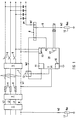
- the installation network in the exemplary embodiment according to FIG. 1 has a house connection 1, a counter 2 and conductor 3, which are protected by short-circuit pre-fuses 4.
- the conductors 3 are further protected by a residual current device 5 and by a circuit breaker 6.
- the installation network has a neutral conductor 7 and an earthing system with equipotential bonding bar 8.
- the equipotential bonding bar 8 is grounded via a grounding conductor 9 at a grounding resistance 10, Rea.
- a test current transmitter 11 is connected to the equipotential bonding bar 8.
- the test current transmitter can in particular be designed as an oscillator.
- the test current from the test current transmitter 11 can be applied to the equipotential bonding bar 8 via a switching device 12 when a clock T is given.
- the potential on the equipotential bonding bar 8 is monitored by a potential measuring device which detects the second potential, P2.
- Another potential measuring device is assigned to the neutral conductor 7 for detecting a first potential, P1.
- the neutral conductor is connected to earth via a grounding conductor at a known grounding resistance of the network supplying the system, Rev.
- a current meter 13 measures the second current, Ie2, flowing through the grounding conductor 9.
- the currents and potentials in a measuring and control unit 14 is detected.
- the measuring and control unit 14 is connected to the mains with its power supply 15.
- a message and control bus can be connected via a bus output 16 be connected.
- For the determination of the earth leakage resistance 10, rea is an existing and the size after known earth resistance 17 of the system supplying Netzes, Rev, included.
- a second potential, P2 which is assigned to the equipotential bonding bar, is again used.
- a first potential, P1 is determined by an earth conductor through an auxiliary earth 18, deer.
- the current, Ie3, through this auxiliary earth 18 is also measured or calculated.
- the current through the auxiliary earth 18, deer is referred to here as a third current, Ie3.
- the current, Ie3, through the auxiliary earth 18, deer also corresponds the current Ie3 emitted by the test current transmitter 11. Instead of that To measure current through the auxiliary earth, the current can also be measured the defined output can be determined by the test current generator 11.
- the earth resistance is 17 of the network supplying the system, Rev, in the provision of earth leakage resistance 10, Rea, not included.
Abstract
Description
Die Erfindung bezieht sich zunächst auf ein Verfahren zur Ermittlung des Erdungsableitungwiderstandes bei einem Installationsnetz mit Neutralleiter, Erdungssystem und Potentialausgleichsschiene, die über einen Erdungsleiter bei einem Erdungsableitwiderstand geerdet ist. Der Erdungsableitwiderstand eines Erdungssystems von elektrischen Anlagen ist für die Schutzmaßnahmen, wie sie in den Errichtungsbestimmungen vorgesehen sind, von tragender Bedeutung. Derartige Schutzmaßnahmen sehen beispielsweise die Fehlerstromschutzschaltung als Personen- und Brandschutz vor. Der Erdungsableitwiderstand ist auch wesentlich für den Überspannungsschutz und für Schirmmaßnahmen unter dem Blickwinkel der elektromagnetischen Verträglichkeit.The invention initially relates to a method for determining of the earth leakage resistance in an installation network with neutral conductor, earthing system and equipotential bonding bar, that through a ground wire at a ground leakage resistor is grounded. The earth leakage resistance of a grounding system of electrical systems is for the protective measures as set out in the establishment regulations are provided of fundamental importance. Such protective measures see for example the residual current protection circuit as personal and fire protection. The earth leakage resistance is also essential for surge protection and for Screening measures from the perspective of electromagnetic Compatibility.
Der Erdungsableitwiderstand kann in bestehenden Anlagen herkömmlich dadurch bestimmt werden, daß bestimmte Leiter aufgetrennt werden und daß besondere Messungen vorgenommen werden. In bestehenden Anlagen ist das in der Regel störend und aufwendig.The earth leakage resistance can be conventional in existing systems be determined by separating certain conductors and that special measurements are made. In existing systems, this is usually bothersome and time-consuming.
Der Erfindung liegt die Aufgabe zugrunde, eine ständige Überwachung des Erdungsableitwiderstandes mit einfachen Maßnahmen bei unbeeinträchtigter Anlage zu ermöglichen.The invention is based, continuous monitoring the task earth leakage resistance with simple measures to enable in an unimpaired system.
Die Lösung der geschilderten Aufgabe erfolgt nach der Erfindung
durch ein Verfahren nach Patentanspruch 1. Die Lösung
erfolgt auch durch ein dafür eingerichtetes Installationsnetz
nach Anspruch 4. The solution to the described problem is solved according to the invention
by a method according to
Die Potentialausgleichsschiene wird von einem Prüfstromgeber
beaufschlagt und der Erdungsableiter der Potentialausgleichsschiene
durch einen Strommesser überwacht. Der Strom wird,
als Zweitstrom genannt, erfaßt. Ein Potential, zweites Potential
genannt, wird an der Potentialausgleichsschiene erfaßt.
Weiter wird entweder ein erstes Potential am Neutralleiter
erfaßt, wobei vom Neutralleiter ein Erdungsleiter bei einem
bekannten Erdungswiderstand des die Anlage versorgenden Netzes,
Rev, zur Erde geführt ist. Der Erdungsableitwiderstand,
Rea, am Erdungsleiter der Potentialausgleichsschiene läßt
sich dann nach dem Algorithmus ermitteln
Oder es wird weiter ein erstes Potential, P1, am erdabgewandten
Ende einer Hilfserde, Reh, erfaßt sowie der Strom durch
diese Hilfserde als sogenannter Drittstrom, Ie3. Der Erdungsableitwiderstand,
Rea, am Erdungsleiter der Potentialausgleichsschiene
läßt sich dann nach dem Algorithmus ermitteln
Der Prüfstromgeber kann ein Oszillator sein oder eine Gleichstromquelle. Bei einer Gleichstromquelle entfällt ein über sogenannte Koppelkapazitäten abfließender Strom, hier erster Strom genannt.The test current transmitter can be an oscillator or a direct current source. In the case of a direct current source, there is no over so-called coupling capacities flowing electricity, here first Called electricity.
Die erste Verfahrensalternative nach Anspruch 1 arbeitet ohne
Hilfserde und läßt sich in TT- und TN-Netzen anwenden. Die
zweite Verfahrensalternative mit Hilfserde kann darüber hinaus
auch in IT-Netzen eingesetzt werden. The first method alternative according to
Bei den Netzformen bezeichnet der erste Buchstabe die Erdungsverhältnisse der Stromquelle:
- T
- direkte Erdung eines Netzpunktes,
- I
- Isolierung aller aktiven Teile von Erde oder Erdung eines Nutzpunktes über eine Impedanz.
- T
- direct earthing of a network point,
- I.
- Isolation of all active parts from earth or earthing of a useful point via an impedance.
Der zweite Buchstabe bedeutet die Erdungsverhältnisse von Körpern in der elektrischen Anlage:
- T
- Körper direkt geerdet, unabhängig von der Erdung der Stromquelle,
- N
- Körper direkt mit dem Betriebserder verbunden.
- T
- Body directly grounded regardless of the grounding of the power source,
- N
- Body directly connected to the plant earth.
Wenn als Prüfstromgeber ein Oszillator mit höherer Frequenz als der Netzfrequenz eingesetzt wird, erzielt man unter dem Blickwinkel der Meßgenauigkeit und Störunempfindlichkeit besonders günstige Verhältnisse. Die Potentialabgriffe P1 und P2 sind vorteilhafterweise hochohmig, vorzugsweise in der Größenordnung von 1 Megohm oder darüber, ausgeführt. Wenn der Drittstrom, Ie3, bei höherer Frequenz eingesetzt wird, können die Meßwerte als Signalpegel aus dem höherfrequenten Prüfstrom ausgefiltert werden.If a test current generator is an oscillator with a higher frequency than the mains frequency is used, one achieves under the Perspective of the measurement accuracy and immunity to interference especially favorable conditions. The potential taps P1 and P2 are advantageously high-impedance, preferably in the Order of 1 megohm or above. If the Third-party current, Ie3, can be used at a higher frequency the measured values as a signal level from the higher-frequency test current be filtered out.
Bei einem Installationsnetz mit Neutralleiter, Erdungssystem
und Potentialausgleichsschiene, die über einen Erdungsleiter
bei einem Erdungsableitwiderstand geerdet ist, kann man folgende
Vorkehrungen treffen:
An der Potentialausgleichsschiene ist ein Prüfstromgeber,
insbesondere ein Oszillator angeschlossen.
Der Erdungsleiter der Potentialausgleichsschiene ist durch
einen Strommesser überwacht, wobei der gemessene Strom hier
als Zweitstrom, Ie2, bezeichnet ist.
Eine Potentialmeßeinrichtung für ein Potential, hier zweites
Potential, P2, genannt, ist der Potentialausgleichsschiene
zugeordnet.
- Entweder ist weiter eine Potentialmeßeinrichtung dem Neutralleiter
zur Erfassung des ersten Potentials, P1, zugeordnet,
wobei vom Neutralleiter ein Erdungsleiter bei einem bekannten
Erdungswiderstand des die Anlage versorgenden Netzes,
Rev, zur Erde gefuhrt ist und der Erdungsableitwiderstand,
Rea, am Erdungsleiter der Potentialausgleichsschiene ermittelbar
ist, gemäß dem Algorithmus
- Oder es ist weiter eine Potentialmeßeinrichtung dem erdabgewandten
Ende einer Hilfserde, Reh, zugeordnet. Hierdurch
kann ein erstes Potential, P1, gemessen werden. Eine Strommeßeinrichtung
ist der Hilfserde zugeordnet, wodurch der hindurchfließende
Strom, hier Drittstrom, EE3, genannt, gemessen
werden. Der Erdungsableitwiderstand, Rea, am Erdungsleiter
der Potentialausgleichsschiene ist dann durch eine Einrichtung
ermittelbar, die den Algorythmus abarbeitet
A test current transmitter, in particular an oscillator, is connected to the equipotential bonding bar.
The earth conductor of the equipotential bonding bar is monitored by an ammeter, the measured current here being referred to as the second current, Ie2.
A potential measuring device for a potential, here called second potential, P2, is assigned to the equipotential bonding bar.
- Either a potential measuring device is also assigned to the neutral conductor for detecting the first potential, P1, an earth conductor being led from the neutral conductor to the earth at a known earth resistance of the system supplying the system, Rev, and the earth leakage resistance, Rea, being determinable on the earth conductor of the equipotential bonding bar , according to the algorithm
- Or there is also a potential measuring device assigned to the end of an auxiliary earth, deer, facing away from the earth. In this way, a first potential, P1, can be measured. A current measuring device is assigned to the auxiliary earth, as a result of which the current flowing through, here called third current, EE3, is measured. The earth leakage resistance, Rea, on the earth conductor of the equipotential bonding bar can then be determined by a device that processes the algorithm
Ein derartiges Installationsnetz erlaubt, auf einfache Weise nach dem erfindungsgemäßen Verfahren zu arbeiten.Such an installation network allows, in a simple manner to work according to the inventive method.
Es ist vorteilhaft, wenn zumindest ein Teil der Erfassungen in einer Meß- und Steuereinheit erfolgt. Die Meß- und Steuereinheit kann an einem Melde- und Steuerbus angeschlossen sein.It is advantageous if at least part of the surveys takes place in a measuring and control unit. The measuring and control unit can be connected to a message and control bus be.
Die Erfindung soll nun anhand von in der Zeichnung grob schematisch
wiedergegebenen Ausführungsbeispielen näher erläutert
werden:
Das Installationsnetz im Ausführungsbeispiel nach FIG 1 weist
einen Hausanschluß 1, einen Zähler 2 und Leiter 3 auf, die
durch Kurzschlußvorsicherungen 4 abgesichert sind. Die Leiter
3 sind weiter durch eine Fehlerstromschutzeinrichtung 5
und durch Leitungsschutzschalter 6 abgesichert. Das Installationsnetz
weist einen Neutralleiter 7 und ein Erdungssystem
mit Potentialausgleichsschiene 8 auf. Die Potentialausgleichsschiene
8 ist über einen Erdungsleiter 9 bei einem Erdungsableitwiderstand
10, Rea, geerdet. An der Potentialausgleichsschiene
8 ist ein Prüfstromgeber 11 angeschlossen. Der
Prüfstromgeber kann insbesondere als Oszillator ausgebildet
sein. Der Prüfstrom vom Prüfstromgeber 11 kann über eine
Schalteinrichtung 12 bei Signal von einem Taktgeber T auf die
Potentialausgleichsschiene 8 gegeben werden. Das Potential
auf der Potentialausgleichsschiene 8 wird durch eine Potentialmeßeinrichtung
überwacht, die das zweite Potential, P2,
erfaßt. Eine weitere Potentialmeßeinrichtung ist dem Neutralleiter
7 zur Erfassung eines ersten Potentials, P1, zugeordnet.
Der Neutralleiter ist über einen Erdungsleiter bei einem
bekannten Erdungswiderstand des die Anlage versorgenden Netzes,
Rev, zur Erde verbunden. Ein Strommesser 13 mißt den
durch den Erdungsleiter 9 fließenden Zweitstrom, Ie2. Der Erdungsableitwiderstand
10, Rea, ist nach dem Algorythmus ermittelbar
Im Ausführungsbeispiel werden die Ströme und Potentiale in
einer Meß- und Steuereinheit 14 erfaßt. Die Meß- und Steuereinheit
14 ist mit ihrem Netzteil 15 am Leitungsnetz angeschlossen.
Über einen Busausgang 16 kann ein Melde- und Steuerbus
angeschlossen werden. Für die Ermittlung des Erdungsableitwiderstandes
10, Rea, ist ein vorhandener und der Größe
nach bekannter Erdungswiderstand 17 des die Anlage versorgenden
Netzes, Rev, einbezogen.In the exemplary embodiment, the currents and potentials in
a measuring and
Im Ausführungsbeispiel nach FIG 2 wird wieder mit einem zweiten
Potential, P2, das der Potentialausgleichsschiene zugeordnet
ist, gearbeitet. Ein erstes Potential, P1, wird jedoch
von einem Erdungsleiter durch eine Hilfserde 18, Reh, bestimmt.
Es wird weiter der Strom, Ie3, durch diese Hilfserde
18 gemessen oder errechnet. Der Strom durch die Hilfserde 18,
Reh, wird hier als Drittstrom, Ie3, bezeichnet. Der Erdungsableitwiderstand
10, Rea, kann dann nach dem Algorythmus ermittelt
werden:
Der Strom, Ie3, durch die Hilfserde 18, Reh, entspricht auch
dem vom Prüfstromgeber 11 abgegebenen Strom Ie3. Statt den
Strom durch die Hilfserde zu messen, kann der Strom auch über
die definierte Abgabe vom Prüfstromgeber 11 bestimmt werden.The current, Ie3, through the
Im Ausführungsbeispiel nach FIG 2 ist der Erdungswiderstand
17 des die Anlage versorgenden Netzes, Rev, in die Bestimmung
des Erdungsableitwiderstandes 10, Rea, nicht einbezogen.In the exemplary embodiment according to FIG. 2, the earth resistance is
17 of the network supplying the system, Rev, in the provision
of
Claims (6)
dadurch gekennzeichnet,
daß die Potentialausgleichsschiene (8) von einem Prüfstromgeber (11) beaufschlagt wird, daß der Erdungsleiter (9) der Potentialausgleichsschiene (8) durch einen Strommesser (13) überwacht wird und dieser als Zweitstrom, Ie2, erfaßt wird, wobei ein zweites Potential, P2, an der Potentialausgleichsschiene (8) erfaßt wird
characterized by
that the equipotential bonding bar (8) is acted upon by a test current transmitter (11), that the grounding conductor (9) of the equipotential bonding bar (8) is monitored by a current meter (13) and this is recorded as a second current, Ie2, a second potential, P2 , is detected on the equipotential bonding bar (8)
dadurch gekennzeichnet,
daß die Potentialausgleichsschiene (8) unmittelbar von einem Prüfstromgeber (11) beaufschlagt wird.Method according to claim 1,
characterized by
that the equipotential bonding bar (8) is acted upon directly by a test current transmitter (11).
dadurch gekennzeichnet,
daß der Prüfstromgeber (11) ein Oszillator ist, der bei Frequenzen höher als der Netzfrequenz betrieben wird, oder eine Gleichstromquelle.The method of claim 1 or 2,
characterized by
that the test current transmitter (11) is an oscillator which is operated at frequencies higher than the mains frequency, or a direct current source.
dadurch gekennzeichnet,
daß an der Potentialausgleichsschiene (8) ein Prüfstromgeber (11), insbesondere ein Oszillator, angeschlossen ist und daß der Erdungsleiter (9) der Potentialausgleichsschiene (8) durch einen Strommesser (13) für einen Zweitstrom, Ie2, überwacht ist, wobei eine Potentialmeßeinrichtung für ein zweites Potential, P2, der Potentialausgleichsschiene (8) zugeordnet ist
characterized by
that a test current transmitter (11), in particular an oscillator, is connected to the equipotential bonding bar (8) and that the grounding conductor (9) of the equipotential bonding bar (8) is monitored by a current meter (13) for a second current, Ie2, a potential measuring device for a second potential, P2, is assigned to the equipotential bonding bar (8)
dadurch gekennzeichnet,
daß zumindest ein Teil der Erfassungen in einer Meß- und Steuereinheit (14) erfolgt.Installation network according to claim 4,
characterized by
that at least some of the detections are carried out in a measuring and control unit (14).
dadurch gekennzeichnet,
daß die Meß- und Steuereinheit (14) an einem Melde- und Steuerbus angeschlossen ist.Installation network according to claim 5,
characterized by
that the measuring and control unit (14) is connected to a message and control bus.
Priority Applications (3)
| Application Number | Priority Date | Filing Date | Title |
|---|---|---|---|
| AT97104191T ATE254768T1 (en) | 1997-03-12 | 1997-03-12 | METHOD FOR DETERMINING THE GROUND LEAKAGE RESISTANCE AND INSTALLATION NETWORK EQUIPPED FOR THIS |
| DE59711030T DE59711030D1 (en) | 1997-03-12 | 1997-03-12 | Procedure for determining the earth leakage resistance and installation network set up for it |
| EP97104191A EP0864873B1 (en) | 1997-03-12 | 1997-03-12 | Procedure for determining the grounding resistance and house wiring adapted for same |
Applications Claiming Priority (1)
| Application Number | Priority Date | Filing Date | Title |
|---|---|---|---|
| EP97104191A EP0864873B1 (en) | 1997-03-12 | 1997-03-12 | Procedure for determining the grounding resistance and house wiring adapted for same |
Publications (2)
| Publication Number | Publication Date |
|---|---|
| EP0864873A1 true EP0864873A1 (en) | 1998-09-16 |
| EP0864873B1 EP0864873B1 (en) | 2003-11-19 |
Family
ID=8226584
Family Applications (1)
| Application Number | Title | Priority Date | Filing Date |
|---|---|---|---|
| EP97104191A Expired - Lifetime EP0864873B1 (en) | 1997-03-12 | 1997-03-12 | Procedure for determining the grounding resistance and house wiring adapted for same |
Country Status (3)
| Country | Link |
|---|---|
| EP (1) | EP0864873B1 (en) |
| AT (1) | ATE254768T1 (en) |
| DE (1) | DE59711030D1 (en) |
Cited By (5)
| Publication number | Priority date | Publication date | Assignee | Title |
|---|---|---|---|---|
| EP2154782A1 (en) * | 2008-08-12 | 2010-02-17 | Rolls-Royce plc | An electromechanical arrangement |
| CN101937022A (en) * | 2010-07-28 | 2011-01-05 | 西南交通大学 | Method for measuring ground resistance of double ground network |
| WO2012156635A1 (en) * | 2011-05-19 | 2012-11-22 | Renault S.A.S. | Device and method for estimating the resistance of the earth connection of an electrical apparatus |
| WO2012168634A1 (en) * | 2011-06-08 | 2012-12-13 | Renault S.A.S. | Device and corresponding method for measuring the resistance of the ground connection of an electrical device |
| CN110854857A (en) * | 2019-09-30 | 2020-02-28 | 中国电力科学研究院有限公司 | Oscillation starting loop and control method thereof |
Families Citing this family (3)
| Publication number | Priority date | Publication date | Assignee | Title |
|---|---|---|---|---|
| CN102508136A (en) * | 2011-12-09 | 2012-06-20 | 江苏镇安电力设备有限公司 | Insulation monitoring method for IT (Isolation Terre) electric system with neutral conductor |
| CN104502724B (en) * | 2014-11-05 | 2017-10-13 | 济南鲁智电子科技有限公司 | A kind of pole tower ground resistance measurement method |
| CN106093589B (en) * | 2016-08-09 | 2018-09-18 | 国网重庆市电力公司南岸供电分公司 | A kind of pole tower ground resistance Accurate measurement and device |
Citations (2)
| Publication number | Priority date | Publication date | Assignee | Title |
|---|---|---|---|---|
| EP0570654A1 (en) * | 1992-05-20 | 1993-11-24 | P.C.E. S.r.l. | A remote eart resistance meter |
| WO1995032434A1 (en) * | 1994-05-24 | 1995-11-30 | Gustavo Sturaro | Process for determining, in tt systems, the ground resistances in the feed system and in the user's installation |
-
1997
- 1997-03-12 DE DE59711030T patent/DE59711030D1/en not_active Expired - Fee Related
- 1997-03-12 AT AT97104191T patent/ATE254768T1/en not_active IP Right Cessation
- 1997-03-12 EP EP97104191A patent/EP0864873B1/en not_active Expired - Lifetime
Patent Citations (2)
| Publication number | Priority date | Publication date | Assignee | Title |
|---|---|---|---|---|
| EP0570654A1 (en) * | 1992-05-20 | 1993-11-24 | P.C.E. S.r.l. | A remote eart resistance meter |
| WO1995032434A1 (en) * | 1994-05-24 | 1995-11-30 | Gustavo Sturaro | Process for determining, in tt systems, the ground resistances in the feed system and in the user's installation |
Non-Patent Citations (1)
| Title |
|---|
| BRINKS ET AL.: "SYSTEM GROUNDING, PROTECTION AND DETECTION FOR CEMENT PLANTS", IEEE TRANSACTIONS ON INDUSTRY APPLICATIONS, vol. IA-17, no. 6, November 1981 (1981-11-01), NEW YORK US, pages 587 - 596, XP002038528 * |
Cited By (12)
| Publication number | Priority date | Publication date | Assignee | Title |
|---|---|---|---|---|
| EP2154782A1 (en) * | 2008-08-12 | 2010-02-17 | Rolls-Royce plc | An electromechanical arrangement |
| US8427117B2 (en) | 2008-08-12 | 2013-04-23 | Rolls-Royce Plc | Electromechanical arrangement |
| CN101937022A (en) * | 2010-07-28 | 2011-01-05 | 西南交通大学 | Method for measuring ground resistance of double ground network |
| CN101937022B (en) * | 2010-07-28 | 2012-08-22 | 西南交通大学 | Method for measuring ground resistance of double ground network |
| WO2012156635A1 (en) * | 2011-05-19 | 2012-11-22 | Renault S.A.S. | Device and method for estimating the resistance of the earth connection of an electrical apparatus |
| FR2975498A1 (en) * | 2011-05-19 | 2012-11-23 | Renault Sa | DEVICE AND METHOD FOR ESTIMATING THE RESISTANCE OF EARTH CONNECTION OF AN ELECTRICAL APPARATUS |
| CN103608686A (en) * | 2011-05-19 | 2014-02-26 | 雷诺股份公司 | Device and method for estimating resistance of earth connection of electrical apparatus |
| US9234858B2 (en) | 2011-05-19 | 2016-01-12 | Renault S.A.S. | Device and method for estimating the resistance of the ground connection for an electrical apparatus |
| CN103608686B (en) * | 2011-05-19 | 2016-03-16 | 雷诺股份公司 | For estimating equipment and the method for the grounding connection resistance of electrical devices |
| WO2012168634A1 (en) * | 2011-06-08 | 2012-12-13 | Renault S.A.S. | Device and corresponding method for measuring the resistance of the ground connection of an electrical device |
| FR2976361A1 (en) * | 2011-06-08 | 2012-12-14 | Renault Sa | DEVICE AND CORRESPONDING METHOD FOR MEASURING THE RESISTANCE OF EARTH CONNECTION OF AN ELECTRICAL APPARATUS |
| CN110854857A (en) * | 2019-09-30 | 2020-02-28 | 中国电力科学研究院有限公司 | Oscillation starting loop and control method thereof |
Also Published As
| Publication number | Publication date |
|---|---|
| EP0864873B1 (en) | 2003-11-19 |
| DE59711030D1 (en) | 2003-12-24 |
| ATE254768T1 (en) | 2003-12-15 |
Similar Documents
| Publication | Publication Date | Title |
|---|---|---|
| DE19960804B4 (en) | Method and apparatus for testing a circuit breaker for arcing line faults | |
| EP1857825B1 (en) | Measuring apparatus | |
| EP0642027B1 (en) | Method and device for detecting earth faults of the conductors in a electrical machine | |
| KR960006867B1 (en) | Method and electrical measuring apparatus for analyzing the impedance of the source of an actual alternating voltage | |
| EP2574939B1 (en) | Isolation fault detection device and device for insulation fault localisation in an unearthed power supply network | |
| DE69916299T2 (en) | METHOD AND DEVICE FOR THE FALL-RELATED LOCALIZATION OF AN ELECTRICAL CABLE | |
| EP0724980A1 (en) | Vehicle with fuel cell or battery supplied electric network | |
| DE3819529C2 (en) | Electrical thermomagnetic and differential protection device | |
| EP0864873B1 (en) | Procedure for determining the grounding resistance and house wiring adapted for same | |
| DE102011017051B4 (en) | Monitoring device for an isolated network of a photovoltaic system, a photovoltaic system with such a monitoring device and a method for safe operation of a photovoltaic system | |
| DE19545267C2 (en) | Method for obtaining faulty loops in signals characterizing a multi-phase electrical power supply network | |
| DE2153341C3 (en) | Test circuit for determining impermissible touch voltages on electrical devices | |
| EP0763745B1 (en) | Method and device for testing electrical apparatus with protective earth | |
| DE102009054834A1 (en) | Connector cable for use in e.g. distribution socket, has coupling connected with counter piece of electric device so that resistance of measuring circuit is measured and warning signal is output during resistance exceedance | |
| EP1001270B1 (en) | Method for testing a ground connection | |
| DE102022106394B3 (en) | Method and monitoring device for determining a partial insulation resistance and a partial system leakage capacitance in a branched unearthed power supply system | |
| DE2443351C3 (en) | Ammeter | |
| WO2003073577A1 (en) | Testing arrangement for a power circuit breaker provided with an electronic trip element | |
| DE3712783A1 (en) | Method for checking the operability of a test device for high-voltage conductors and test device | |
| WO1998026299A1 (en) | Device to detect the state of n power capacitors forming part of a high-voltage power capacitor bank | |
| DE3819880C2 (en) | Method for determining the course of live power lines as well as the device and the two-pole periodically changing impedance for carrying out the method | |
| EP0454013B1 (en) | Measurement circuit for detecting a current | |
| DE2819776C2 (en) | ||
| DE19642639B4 (en) | Device for testing the connection of Meßleiterpaaren | |
| EP0363830A1 (en) | Electrical installation with a galvanic signal-carrying conductor, and an interference indicator therefor |
Legal Events
| Date | Code | Title | Description |
|---|---|---|---|
| PUAI | Public reference made under article 153(3) epc to a published international application that has entered the european phase |
Free format text: ORIGINAL CODE: 0009012 |
|
| AK | Designated contracting states |
Kind code of ref document: A1 Designated state(s): AT BE CH DE ES FR GB IT LI NL SE |
|
| AX | Request for extension of the european patent |
Free format text: AL;LT;LV;RO;SI |
|
| 17P | Request for examination filed |
Effective date: 19981005 |
|
| AKX | Designation fees paid |
Free format text: AT BE CH DE ES FR GB IT LI NL SE |
|
| RBV | Designated contracting states (corrected) |
Designated state(s): AT BE CH DE ES FR GB IT LI NL SE |
|
| GRAH | Despatch of communication of intention to grant a patent |
Free format text: ORIGINAL CODE: EPIDOS IGRA |
|
| GRAS | Grant fee paid |
Free format text: ORIGINAL CODE: EPIDOSNIGR3 |
|
| GRAA | (expected) grant |
Free format text: ORIGINAL CODE: 0009210 |
|
| AK | Designated contracting states |
Kind code of ref document: B1 Designated state(s): AT BE CH DE ES FR GB IT LI NL SE |
|
| PG25 | Lapsed in a contracting state [announced via postgrant information from national office to epo] |
Ref country code: NL Free format text: LAPSE BECAUSE OF FAILURE TO SUBMIT A TRANSLATION OF THE DESCRIPTION OR TO PAY THE FEE WITHIN THE PRESCRIBED TIME-LIMIT Effective date: 20031119 Ref country code: IT Free format text: LAPSE BECAUSE OF FAILURE TO SUBMIT A TRANSLATION OF THE DESCRIPTION OR TO PAY THE FEE WITHIN THE PRESCRIBED TIME-LIMIT;WARNING: LAPSES OF ITALIAN PATENTS WITH EFFECTIVE DATE BEFORE 2007 MAY HAVE OCCURRED AT ANY TIME BEFORE 2007. THE CORRECT EFFECTIVE DATE MAY BE DIFFERENT FROM THE ONE RECORDED. Effective date: 20031119 Ref country code: GB Free format text: LAPSE BECAUSE OF FAILURE TO SUBMIT A TRANSLATION OF THE DESCRIPTION OR TO PAY THE FEE WITHIN THE PRESCRIBED TIME-LIMIT Effective date: 20031119 |
|
| REG | Reference to a national code |
Ref country code: GB Ref legal event code: FG4D Free format text: NOT ENGLISH |
|
| REG | Reference to a national code |
Ref country code: CH Ref legal event code: EP |
|
| REF | Corresponds to: |
Ref document number: 59711030 Country of ref document: DE Date of ref document: 20031224 Kind code of ref document: P |
|
| PG25 | Lapsed in a contracting state [announced via postgrant information from national office to epo] |
Ref country code: SE Free format text: LAPSE BECAUSE OF FAILURE TO SUBMIT A TRANSLATION OF THE DESCRIPTION OR TO PAY THE FEE WITHIN THE PRESCRIBED TIME-LIMIT Effective date: 20040219 |
|
| PG25 | Lapsed in a contracting state [announced via postgrant information from national office to epo] |
Ref country code: ES Free format text: LAPSE BECAUSE OF FAILURE TO SUBMIT A TRANSLATION OF THE DESCRIPTION OR TO PAY THE FEE WITHIN THE PRESCRIBED TIME-LIMIT Effective date: 20040302 |
|
| PG25 | Lapsed in a contracting state [announced via postgrant information from national office to epo] |
Ref country code: AT Free format text: LAPSE BECAUSE OF NON-PAYMENT OF DUE FEES Effective date: 20040312 |
|
| PG25 | Lapsed in a contracting state [announced via postgrant information from national office to epo] |
Ref country code: LI Free format text: LAPSE BECAUSE OF NON-PAYMENT OF DUE FEES Effective date: 20040331 Ref country code: CH Free format text: LAPSE BECAUSE OF NON-PAYMENT OF DUE FEES Effective date: 20040331 Ref country code: BE Free format text: LAPSE BECAUSE OF NON-PAYMENT OF DUE FEES Effective date: 20040331 |
|
| NLV1 | Nl: lapsed or annulled due to failure to fulfill the requirements of art. 29p and 29m of the patents act | ||
| GBV | Gb: ep patent (uk) treated as always having been void in accordance with gb section 77(7)/1977 [no translation filed] |
Effective date: 20031119 |
|
| ET | Fr: translation filed | ||
| PLBE | No opposition filed within time limit |
Free format text: ORIGINAL CODE: 0009261 |
|
| STAA | Information on the status of an ep patent application or granted ep patent |
Free format text: STATUS: NO OPPOSITION FILED WITHIN TIME LIMIT |
|
| BERE | Be: lapsed |
Owner name: *SIEMENS A.G. Effective date: 20040331 |
|
| 26N | No opposition filed |
Effective date: 20040820 |
|
| REG | Reference to a national code |
Ref country code: CH Ref legal event code: PL |
|
| PGFP | Annual fee paid to national office [announced via postgrant information from national office to epo] |
Ref country code: FR Payment date: 20050331 Year of fee payment: 9 |
|
| PGFP | Annual fee paid to national office [announced via postgrant information from national office to epo] |
Ref country code: DE Payment date: 20050519 Year of fee payment: 9 |
|
| PG25 | Lapsed in a contracting state [announced via postgrant information from national office to epo] |
Ref country code: DE Free format text: LAPSE BECAUSE OF NON-PAYMENT OF DUE FEES Effective date: 20061003 |
|
| REG | Reference to a national code |
Ref country code: FR Ref legal event code: ST Effective date: 20061130 |
|
| PG25 | Lapsed in a contracting state [announced via postgrant information from national office to epo] |
Ref country code: FR Free format text: LAPSE BECAUSE OF NON-PAYMENT OF DUE FEES Effective date: 20060331 |