EP0864698B1 - Self-loading mobile crusher system - Google Patents
Self-loading mobile crusher system Download PDFInfo
- Publication number
- EP0864698B1 EP0864698B1 EP98250078A EP98250078A EP0864698B1 EP 0864698 B1 EP0864698 B1 EP 0864698B1 EP 98250078 A EP98250078 A EP 98250078A EP 98250078 A EP98250078 A EP 98250078A EP 0864698 B1 EP0864698 B1 EP 0864698B1
- Authority
- EP
- European Patent Office
- Prior art keywords
- vehicle
- spoil
- debris
- conveyor
- crushing
- Prior art date
- Legal status (The legal status is an assumption and is not a legal conclusion. Google has not performed a legal analysis and makes no representation as to the accuracy of the status listed.)
- Expired - Lifetime
Links
- 239000002689 soil Substances 0.000 claims description 3
- 239000011435 rock Substances 0.000 description 15
- 239000000463 material Substances 0.000 description 14
- 238000009412 basement excavation Methods 0.000 description 9
- 230000000712 assembly Effects 0.000 description 4
- 238000000429 assembly Methods 0.000 description 4
- 238000000034 method Methods 0.000 description 2
- 230000008569 process Effects 0.000 description 2
- 239000011449 brick Substances 0.000 description 1
- 239000004568 cement Substances 0.000 description 1
- 239000004035 construction material Substances 0.000 description 1
- 230000007797 corrosion Effects 0.000 description 1
- 238000005260 corrosion Methods 0.000 description 1
- 230000007246 mechanism Effects 0.000 description 1
- 230000000087 stabilizing effect Effects 0.000 description 1
- 230000032258 transport Effects 0.000 description 1
- 239000002023 wood Substances 0.000 description 1
Images


Classifications
-
- B—PERFORMING OPERATIONS; TRANSPORTING
- B02—CRUSHING, PULVERISING, OR DISINTEGRATING; PREPARATORY TREATMENT OF GRAIN FOR MILLING
- B02C—CRUSHING, PULVERISING, OR DISINTEGRATING IN GENERAL; MILLING GRAIN
- B02C21/00—Disintegrating plant with or without drying of the material
- B02C21/02—Transportable disintegrating plant
-
- E—FIXED CONSTRUCTIONS
- E02—HYDRAULIC ENGINEERING; FOUNDATIONS; SOIL SHIFTING
- E02F—DREDGING; SOIL-SHIFTING
- E02F3/00—Dredgers; Soil-shifting machines
- E02F3/04—Dredgers; Soil-shifting machines mechanically-driven
- E02F3/08—Dredgers; Soil-shifting machines mechanically-driven with digging elements on an endless chain
- E02F3/085—Dredgers; Soil-shifting machines mechanically-driven with digging elements on an endless chain with auxiliary or additional digging elements other than digging elements on an endless chain
-
- E—FIXED CONSTRUCTIONS
- E02—HYDRAULIC ENGINEERING; FOUNDATIONS; SOIL SHIFTING
- E02F—DREDGING; SOIL-SHIFTING
- E02F3/00—Dredgers; Soil-shifting machines
- E02F3/04—Dredgers; Soil-shifting machines mechanically-driven
- E02F3/76—Graders, bulldozers, or the like with scraper plates or ploughshare-like elements; Levelling scarifying devices
- E02F3/80—Component parts
- E02F3/84—Drives or control devices therefor, e.g. hydraulic drive systems
- E02F3/844—Drives or control devices therefor, e.g. hydraulic drive systems for positioning the blade, e.g. hydraulically
-
- E—FIXED CONSTRUCTIONS
- E02—HYDRAULIC ENGINEERING; FOUNDATIONS; SOIL SHIFTING
- E02F—DREDGING; SOIL-SHIFTING
- E02F5/00—Dredgers or soil-shifting machines for special purposes
- E02F5/22—Dredgers or soil-shifting machines for special purposes for making embankments; for back-filling
- E02F5/223—Dredgers or soil-shifting machines for special purposes for making embankments; for back-filling for back-filling
- E02F5/226—Dredgers or soil-shifting machines for special purposes for making embankments; for back-filling for back-filling with means for processing the soil, e.g. screening belts, separators; Padding machines
Definitions
- the present invention relates to an apparatus for padding pipe, and more particularly to a self-loading mobile crusher system for reducing the size of debris.
- FIGS. 1-5 wherein like numerals are utilized for like and corresponding components, the present self-loading mobile crusher system is illustrated, and is generally identified by the numeral 10.
- System 10 is utilized for reducing the size of debris disposed in a pile such as, for example, a spoil pile created as a result of excavation.
- FIG. 1 illustrates a spoil pile 12 including rocks 14.
- System 10 is adapted to be positioned on a surface 16 of spoil pile 12. Surface 16 is above a ground surface 18 underlying spoil pile 12.
- spoke or “debris” shall include, for example, rocks and soil excavated from a trench, construction material resulting from demolition of a building, such as, brick, cement, wood, and wallboard, or vegetation, such as, for example, downed trees and tree limbs.
- an important aspect of the present invention is to create a level surface 16 for system 10 as system 10 moves over surface 16 of spoil pile 12.
- Tracked vehicle 20 includes a pair of endless track elements 22 and 24 mounted on the right and left sides of tracked vehicle 20, respectively.
- Track elements 22 and 24 are provided with drive sprockets which are driven by a chain from a hydraulic motor output (not shown).
- Tracked vehicle 20 includes a mainframe 26 and a cab 28.
- Loading assembly 30 is pivotally mounted to mainframe 26 utilizing a pair of hydraulic cylinders 32.
- Loading assembly 30 includes a pair of auger assemblies 36 and 38 for collecting and directing spoil to a spoil transfer assembly, generally identified by the numeral 40.
- Spoil transfer assembly 40 includes a conveyor 42 having first and second ends 42a and 42b, and a conveyor 44 having ends 44a and 44b.
- Conveyor 42 is mounted on loading assembly 30 and receives spoil from spoil pile 12 at end 42a which is located between auger assemblies 36 and 38. Conveyor 42 transports spoil from end 42a to end 42b disposed adjacent to mainframe 26.
- Conveyor 44 is mounted to mainframe 26, and receives spoil at end 44a from conveyor end 42b. Spoil is then transported to end 44b of conveyor 44 to be deposited into a hopper 50 disposed on mainframe 26.
- Conveyors 42 and 44 include a plurality of spaced elements 52 for contacting and moving spoil from loading assembly 30 to hopper 50.
- Crushing assembly 60 may comprise, for example, a hammer mill having traveling breaker plates which is described in U.S. Patent No. 3,099,408, which description and drawings are incorporated herein by reference.
- Crushing assembly 60 functions to reduce spoil pile 12 and rocks 14 to a fine material to be returned to the area surrounding a pipe in an excavated trench.
- the crushed material is returned to the excavation via a conveyor 62 connected to mainframe 26.
- Conveyor 62 may deposit crushed material onto ground surface 18 to a location out of the fonvard path of vehicle 20 or into an excavated trench for pipeline padding purposes.
- Spoil transfer assembly 40, conveyors 42, 44, and 62, hopper 50 and crushing assembly 60 are all mounted for movement on vehicle 20 which provides vehicular support for the above-identified components of system 10.
- vehicle 20 provides vehicular support for the above-identified components of system 10.
- system 10 can be moved over the top surface of a spoil pile, such as illustrated in FIGS. 1, 4, and 5 in order to crush debris from a top portion of the spoil pile 12. Since it is only necessary for fine grade material to be disposed around a pipe within an excavated trench, once the spoil has been crushed and the created fine grade material is deposited around the pipe, any remaining spoil having rocks 14 may be filled in the excavated trench on top of the fine grade material. As a result, the entire spoil pile 12 need not be crushed to a fine grade of material for pipeline padding. It is therefore desirable that tracked vehicle 20 move along surface 16 of spoil pile 12, receive spoil and rocks 14 from spoil pile 12 for crushing and subsequent delivery to an excavated trench.
- tracked vehicle 20 Since tracked vehicle 20 is adapted to travel over surface 16 of spoil pile 12, it is essential that tracked vehicle 20 operate in a stable position and that track elements 22 and 24 are supported in a horizontal position. Otherwise, either one or both of track elements 22 and 24 may become unstable and tracked vehicle 20 may tilt and slide off of surface 16.
- a mold board 70 is provided for creating a level surface 16 for supporting vehicle 20.
- Mold board 70 is pivotally attached to spoil transfer assembly 40 and is positioned forward of mainframe 26. Referring simultaneously to FIGS. 2 and 3, mold board 70 extends between auger assemblies 36 and 38, and rearward of conveyor 42. Mold board 70 is pivotally attached to spoil transfer assembly 40 utilizing hydraulic cylinders 74 and 76. Hydraulic cylinders 74 and 76 may be manually operated by an operator of system 10 or automatically operated based upon an automatic level sensing system (not shown). Mold board 70 pivots about a shaft 78. Mold board 70 includes an edge 80 and a spoil engaging surface 82. Spoil engaging surface 82 is disposed below conveyor end 42a of conveyor 42 between auger assemblies 36 and 38.
- mold board 70 includes slots 86 and 88. Stops 90 and 92 are provided on spoil transfer assembly 40 and are positioned within slots 86 and 88, respectively. Mold board 70 is pivotally mounted on transfer assembly 40 to move between a horizontal position as illustrated in FIG. 3, to an extreme left position and to an extreme right position as illustrated in FIGS. 4 and 5, respectively. In the left position (FIG. 4), edge 80 of mold board 70 adjacent to auger 38 engages spoil pile 12 and edge 80 of mold board 70 adjacent to auger 36 creates a gap 100 between auger 36 and surface 16 thereby allowing spoil and rock 14 from spoil pile 12 to pass beneath auger 36 to the area between transfer assembly 40 and mainframe 26 such that spoil and rock 14 increase the height of surface 16 below track element 22. Passage of spoil and rock 14 to track element 22 enables tracked vehicle 20 to stabilize in the event that mainframe 26 is tilting to the right. In the position of mold board 70 illustrated in FIG. 4, stop 90 engages the lowermost portion of slot 86 (FIG. 3).
- mold board 70 is pivoted to the position illustrated in FIG. 5 wherein edge 80 of mold board 70 engages spoil pile 12 below auger 36 to thereby create a gap 102 between auger 38 and surface 16. In this manner, spoil and rock 14 can pass from below transfer assembly 40 to increase the height of surface 16 below track element 24 and thereby raise the left side of tracked vehicle 20, thereby stabilizing the position of tracked vehicle 20 on surface 16. Mold board 70 in the position illustrated in FIG. 5 positions stop 92 to the bottom most position of slot 88 (FIG. 3).
- mold board 70 provides for a self-leveling function in order to maintain tracked vehicle 20 in a stable position on surface 16 of spoil pile 12.
- the positioning of mold board 70 controls the passage of spoil and rock 14 to increase the height of surface 16 under either track element 22 or track element 24 and controls the amount of material passing under track elements 22 and 24 due to the pivotal positioning of mold board 70 to either increase or decrease the size of gaps 100 and 102.
- System 10 is self-loading due to the operation of augers 36 and 38 as tracked vehicle 20 moves along surface 16 of spoil pile 12.
- Conveyors 42 and 44 provide a continuous flow of spoil and rocks 14 to crusher assembly 60.
- the speed of each conveyor 42 and 44 is independently controlled and together with controlling the speed of tracked vehicle 20 a continuous flow of material to hopper 50 is maintained to feed crusher assembly 60 in a continuous manner.
- the use of traveling breaker plates in crusher assembly 60 allows for crushing of spoil which may be wet, or contain clay-like material which would otherwise jam a crushing device.
- gaps 100 and 102 may range from about three inches to about twelve inches to thereby maintain tracked vehicle 20 on approximately a 30 degree incline on the spoil pile 12.
Landscapes
- Engineering & Computer Science (AREA)
- Mining & Mineral Resources (AREA)
- Mechanical Engineering (AREA)
- Civil Engineering (AREA)
- General Engineering & Computer Science (AREA)
- Structural Engineering (AREA)
- Food Science & Technology (AREA)
- Disintegrating Or Milling (AREA)
- Vehicle Cleaning, Maintenance, Repair, Refitting, And Outriggers (AREA)
Description
- The present invention relates to an apparatus for padding pipe, and more particularly to a self-loading mobile crusher system for reducing the size of debris.
- Such a self-loading mobile crusher system is already known from WO-A-97/04183, showing the features of the preamble of
claims 1 and 10. - In the process of laying pipe, an excavation is made utilizing, for example, a backhoe, trenching machine, or the like. Excavated rocks and soil, which is commonly referred to as "spoil", is piled to one side of the excavation. After the pipe is laid in the excavation, the excavation is usually filled in with the spoil. However, it is important that large rocks in the spoil do not come into contact with the pipe, which may damage the pipe and cause unnecessary corrosion of the pipe. For this reason, it is common to fill the trench around the portion of the excavation surrounding the pipe with fine material which has been separated from the spoil. This process is known as padding, and has been a time consuming and expensive stage of laying an underground pipeline.
- Previously developed systems have utilized mechanisms such as, for example, screens for separating fine material out of the spoil and transporting the separated fine material into an excavation. Such systems are not efficient, and result in the need to dispose of rock which is separated from the fine material.
- A need has thus arisen for a system for reducing the size of debris typically found in a spoil pile for padding pipe.
- The invention is solved by the features of the characterizing portion of
claims 1 and 10. - For a more complete understanding of the present invention and for further advantages thereof, reference is now made to the following Description of the Preferred Embodiments taken in conjunction with the accompanying Drawings in which:
- FIG. 1 is a side elevational view of the present self-loading mobile crusher system shown on the surface of a spoil pile;
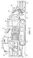
- FIG. 2 is a side elevational view of the present self-loading mobile crusher system;
- FIG. 3 is a sectional view taken generally along sectional lines 3-3 of FIG. 2 illustrating the present mold board;
- FIG. 4 is a front elevational view of the present self-loading mobile crusher system illustrating the mold board in a first position; and
- FIG. 5 is a front elevational view of the present self-loading mobile crusher system illustrating the mold board in a second position.
-
- Referring simultaneously to FIGS. 1-5, wherein like numerals are utilized for like and corresponding components, the present self-loading mobile crusher system is illustrated, and is generally identified by the
numeral 10.System 10 is utilized for reducing the size of debris disposed in a pile such as, for example, a spoil pile created as a result of excavation. FIG. 1 illustrates aspoil pile 12 includingrocks 14.System 10 is adapted to be positioned on asurface 16 ofspoil pile 12.Surface 16 is above aground surface 18 underlyingspoil pile 12. As used herein, "spoil" or "debris" shall include, for example, rocks and soil excavated from a trench, construction material resulting from demolition of a building, such as, brick, cement, wood, and wallboard, or vegetation, such as, for example, downed trees and tree limbs. - As will subsequently be described, an important aspect of the present invention is to create a
level surface 16 forsystem 10 assystem 10 moves oversurface 16 ofspoil pile 12. -
System 10 includes a self-propelled tracked vehicle, generally identified by thenumeral 20. Trackedvehicle 20 includes a pair ofendless track elements vehicle 20, respectively.Track elements vehicle 20 includes amainframe 26 and acab 28. - Mounted to tracked
vehicle 20 for movement with trackedvehicle 20 is a debris loading assembly, generally identified by thenumeral 30. Loadingassembly 30 is pivotally mounted tomainframe 26 utilizing a pair ofhydraulic cylinders 32. Loadingassembly 30 includes a pair ofauger assemblies numeral 40.Spoil transfer assembly 40 includes aconveyor 42 having first andsecond ends conveyor 44 havingends Conveyor 42 is mounted onloading assembly 30 and receives spoil fromspoil pile 12 atend 42a which is located betweenauger assemblies Conveyor 42 transports spoil fromend 42a toend 42b disposed adjacent tomainframe 26.Conveyor 44 is mounted tomainframe 26, and receives spoil atend 44a fromconveyor end 42b. Spoil is then transported toend 44b ofconveyor 44 to be deposited into ahopper 50 disposed onmainframe 26.Conveyors elements 52 for contacting and moving spoil fromloading assembly 30 to hopper 50. - Hopper 50 delivers spoil to a crushing
assembly 60 mounted tomainframe 26. Crushingassembly 60 may comprise, for example, a hammer mill having traveling breaker plates which is described in U.S. Patent No. 3,099,408, which description and drawings are incorporated herein by reference. Crushingassembly 60 functions to reducespoil pile 12 and rocks 14 to a fine material to be returned to the area surrounding a pipe in an excavated trench. The crushed material is returned to the excavation via aconveyor 62 connected tomainframe 26.Conveyor 62 may deposit crushed material ontoground surface 18 to a location out of the fonvard path ofvehicle 20 or into an excavated trench for pipeline padding purposes. -
Spoil transfer assembly 40,conveyors hopper 50 and crushingassembly 60 are all mounted for movement onvehicle 20 which provides vehicular support for the above-identified components ofsystem 10. As a result, theentire system 10 may be moved alongside an excavation at a site in order to quickly and efficiently pad a pipeline. Furthermore,system 10 can be moved over the top surface of a spoil pile, such as illustrated in FIGS. 1, 4, and 5 in order to crush debris from a top portion of thespoil pile 12. Since it is only necessary for fine grade material to be disposed around a pipe within an excavated trench, once the spoil has been crushed and the created fine grade material is deposited around the pipe, any remainingspoil having rocks 14 may be filled in the excavated trench on top of the fine grade material. As a result, theentire spoil pile 12 need not be crushed to a fine grade of material for pipeline padding. It is therefore desirable that trackedvehicle 20 move alongsurface 16 ofspoil pile 12, receive spoil androcks 14 fromspoil pile 12 for crushing and subsequent delivery to an excavated trench. - Since tracked
vehicle 20 is adapted to travel oversurface 16 ofspoil pile 12, it is essential that trackedvehicle 20 operate in a stable position and thattrack elements track elements vehicle 20 may tilt and slide off ofsurface 16. - In accordance with the present invention, a
mold board 70 is provided for creating alevel surface 16 for supportingvehicle 20.Mold board 70 is pivotally attached tospoil transfer assembly 40 and is positioned forward ofmainframe 26. Referring simultaneously to FIGS. 2 and 3,mold board 70 extends betweenauger assemblies conveyor 42.Mold board 70 is pivotally attached tospoil transfer assembly 40 utilizinghydraulic cylinders Hydraulic cylinders system 10 or automatically operated based upon an automatic level sensing system (not shown). Moldboard 70 pivots about ashaft 78.Mold board 70 includes anedge 80 and a spoilengaging surface 82. Spoilengaging surface 82 is disposed belowconveyor end 42a ofconveyor 42 betweenauger assemblies - As illustrated in FIG. 3,
mold board 70 includesslots Stops spoil transfer assembly 40 and are positioned withinslots Mold board 70 is pivotally mounted ontransfer assembly 40 to move between a horizontal position as illustrated in FIG. 3, to an extreme left position and to an extreme right position as illustrated in FIGS. 4 and 5, respectively. In the left position (FIG. 4),edge 80 ofmold board 70 adjacent to auger 38 engagesspoil pile 12 and edge 80 ofmold board 70 adjacent to auger 36 creates agap 100 betweenauger 36 andsurface 16 thereby allowing spoil androck 14 fromspoil pile 12 to pass beneathauger 36 to the area betweentransfer assembly 40 andmainframe 26 such that spoil androck 14 increase the height ofsurface 16 belowtrack element 22. Passage of spoil androck 14 to trackelement 22 enables trackedvehicle 20 to stabilize in the event thatmainframe 26 is tilting to the right. In the position ofmold board 70 illustrated in FIG. 4, stop 90 engages the lowermost portion of slot 86 (FIG. 3). - In order to allow spoil and
rocks 14 fromspoil pile 12 to pass undertrack element 24 in order to stabilize trackedvehicle 20,mold board 70 is pivoted to the position illustrated in FIG. 5 whereinedge 80 ofmold board 70 engagesspoil pile 12 belowauger 36 to thereby create agap 102 betweenauger 38 andsurface 16. In this manner, spoil androck 14 can pass from belowtransfer assembly 40 to increase the height ofsurface 16 belowtrack element 24 and thereby raise the left side of trackedvehicle 20, thereby stabilizing the position of trackedvehicle 20 onsurface 16.Mold board 70 in the position illustrated in FIG. 5 positions stop 92 to the bottom most position of slot 88 (FIG. 3). - It therefore can be seen that
mold board 70 provides for a self-leveling function in order to maintain trackedvehicle 20 in a stable position onsurface 16 ofspoil pile 12. The positioning ofmold board 70 controls the passage of spoil androck 14 to increase the height ofsurface 16 under eithertrack element 22 ortrack element 24 and controls the amount of material passing undertrack elements mold board 70 to either increase or decrease the size ofgaps -
System 10 is self-loading due to the operation ofaugers vehicle 20 moves alongsurface 16 ofspoil pile 12.Conveyors rocks 14 tocrusher assembly 60. The speed of eachconveyor hopper 50 is maintained to feedcrusher assembly 60 in a continuous manner. The use of traveling breaker plates incrusher assembly 60 allows for crushing of spoil which may be wet, or contain clay-like material which would otherwise jam a crushing device. - The size of
gaps vehicle 20 on approximately a 30 degree incline on thespoil pile 12.
Claims (18)
- A self-loading mobile crusher system for reducing the size of debris disposed in a pile having a surface, the system comprising: a vehicle having first and second sides and adapted for movement on the surface of the debris pile, said vehicle including first and second surface engaging devices disposed on said vehicle sides; means (60) for crushing debris (22, 24), said crushing means being connected to said vehicle for movement with said vehicle; means (30) for transferring debris from the debris pile to said crushing means (60), said transferring means (30) being connected to said vehicle for movement with said vehicle, characterized in that there are provided means (36, 38) disposed between said sides of said vehicle, adjacent said transferring means (30); and being connected to said vehicle for movement with said vehicle for controlling passage of debris from the debris pile forward of said surface engaging devices to a position under said surface engaging devices.
- The system of Claim 1 wherein said means for transferring debris includes a conveyor (42).
- The system of Claim 2 wherein said conveyor includes a plurality of spaced apart elements (52) for contacting and moving debris, said plurality of elements (52) being mounted for movement in an endless path.
- The system of Claim 1 and further including means (62) for returning crushed debris to a location out of the forward path of said vehicle.
- The system of Claim 1 wherein said means for transferring debris includes: a first conveyor (42) having first (42a) and second ends (42b), said first end (42a) thereof disposed for receiving debris from the debris pile; and a second conveyor (44) having first (44a) and second ends (44b), said first end (44a) thereof being adapted to receive debris from said second end (42b) of said First conveyor (42) for transporting debris to said second end (44b) of said second conveyor (44), said second end (44b) of said second conveyor being disposed adjacent to said means for crushing (60).
- The system of Claim 1 wherein said means for crushing debris includes traveling breaker plates.
- The system of Claim 1 wherein said vehicle comprises a self-propelled tracked vehicle.
- The system of Claim 1 wherein said means for controlling passage of debris includes a mold board (70).
- The system of Claim 8 wherein said mold board is pivotally-mounted to move between first and second positions for selectively allowing debris to pass below said first surface engaging device in said first position and debris to pass below said second surface engaging device in said second position to thereby selectively increase the height of the surface under either side of said vehicle on which said vehicle moves.
- A pipeline padding system for movement on a surface in a forward direction along the side of an excavated pipeline trough while crushing spoil excavated from the trough and piled on the underlying soil surface and placing crushed spoil in the pipeline trough, the padding system comprising: a vehicle having l'irst and second sides and adapted for movement on the surface along the pipeline trough, said vehicle including first and second surface engaging devices (22,24) disposed on said vehicle sides; means for crushing spoil, said crushing means (60) being connected to said vehicle for movement with said vehicle; means (30) for transferring spoil from the spoil pile to said crushing means, said transferring means being connected to said vehicle for movement with said vehicle, characterized in that there are provided means disposed between said sides of said vehicle, adjacent said transferring means (30), and being connected to said vehicle for movement with said vehicle for controlling passage of spoil from the spoil pile forward of said surface engaging devices to a position under said surface engaging devices.
- The system of Claim 10 wherein said means for transferring spoil includes a conveyor (42).
- The system of Claim 11 wherein said conveyor includes a plurality of spaced apart elements (52) for contacting and moving spoil, said plurality of elements (52) being mounted for movement in an endless path.
- The system of Claim 10 and further including means (62) for returning crushed spoil to a location out of the forward path of said vehicle and into the pipeline trough.
- The system of Claim 10 wherein said means for transferring spoil includes: a first conveyor (42) having first (42a) and second (42b) ends, said first end (42a) thereof disposed for receiving spoil from the spoil pile; and second conveyor (44) having first (44a) and second ends (44b), said first end (44a) thereof being adapted to receive spoil from said second end (42b) of said first conveyor (42) for transporting spoil to said second end (44b) of said second conveyor (44), said second end (44b) of said second conveyor being disposed adjacent to said means for crushing (60).
- The system of Claim 10 wherein said means for crushing spoil includes traveling breaker plates.
- The system of Claim 10 wherein said vehicle comprises a self-propelled tracked vehicle.
- The system of Claim 10 wherein said means for controlling - passage of spoil includes a mold board (70).
- The system of Claim 17 wherein said mold board is pivotally mounted to move between first and second positions for selectively allowing spoil to pass below said first surface engaging device in said first position and spoil to pass below said second surface engaging device in said second position to thereby selectively increase the height of the surface under either side of said vehicle on which said vehicle moves.
Applications Claiming Priority (2)
| Application Number | Priority Date | Filing Date | Title |
|---|---|---|---|
| US811422 | 1997-03-05 | ||
| US08/811,422 US5788168A (en) | 1997-03-05 | 1997-03-05 | Self-loading mobile crusher system |
Publications (2)
| Publication Number | Publication Date |
|---|---|
| EP0864698A1 EP0864698A1 (en) | 1998-09-16 |
| EP0864698B1 true EP0864698B1 (en) | 2000-08-02 |
Family
ID=25206511
Family Applications (1)
| Application Number | Title | Priority Date | Filing Date |
|---|---|---|---|
| EP98250078A Expired - Lifetime EP0864698B1 (en) | 1997-03-05 | 1998-03-04 | Self-loading mobile crusher system |
Country Status (4)
| Country | Link |
|---|---|
| US (2) | US5788168A (en) |
| EP (1) | EP0864698B1 (en) |
| DE (1) | DE69800236T2 (en) |
| ES (1) | ES2149629T3 (en) |
Families Citing this family (20)
| Publication number | Priority date | Publication date | Assignee | Title |
|---|---|---|---|---|
| US6318930B1 (en) * | 1995-07-20 | 2001-11-20 | Erik D. Scudder | Efficient method and pulverizer for pipeline trench padding |
| US5788168A (en) * | 1997-03-05 | 1998-08-04 | Trencor, Inc. | Self-loading mobile crusher system |
| US6138837A (en) * | 1998-05-01 | 2000-10-31 | Santa Cruz; Cathy D. | Combination screen/conveyor device removably attachable to a vehicle |
| US6139223A (en) * | 1998-11-20 | 2000-10-31 | Snyder; Robert Wayne | Trench filler |
| AUPP939899A0 (en) * | 1999-03-24 | 1999-04-15 | Cardiff, Darren | An apparatus for digging a trench |
| DE10019748C1 (en) * | 2000-04-20 | 2001-09-20 | Man Takraf Foerdertechnik Gmbh | Device, to test ability to cut and mine critical material, has two-track running gear, frame with drive assembly, control platform and horizontal cutting roller connected to conveyor |
| US7186059B2 (en) | 2003-04-22 | 2007-03-06 | Tommy Barnes | Padding machine and method of use |
| US7476733B2 (en) | 2005-03-25 | 2009-01-13 | The United States Of America As Represented By The Department Of Health And Human Services | Development of a real-time PCR assay for detection of pneumococcal DNA and diagnosis of pneumococccal disease |
| US7886463B2 (en) * | 2005-06-29 | 2011-02-15 | Worldwide Machinery Pipeline Division | Pipeline padding machine |
| US7927059B2 (en) * | 2006-10-11 | 2011-04-19 | Worldwide Machinery Pipeline Division | Pipeline padding machine with a debris-resistant escalator assembly |
| US20080092410A1 (en) * | 2006-10-19 | 2008-04-24 | Layh Ricky L | Pipeline padding machine |
| CA2696469C (en) | 2007-07-13 | 2015-11-24 | Leonardi Manufacturing Co. | Wood chip collection system |
| US20090090522A1 (en) * | 2007-10-04 | 2009-04-09 | Michael Platt | Material loader apparatus and method |
| AU2011210035B2 (en) * | 2010-01-26 | 2016-12-15 | Husqvarna Ab | A laying machine |
| US8789784B2 (en) | 2010-05-14 | 2014-07-29 | Ange Construction Co. | Mobile self-contained loading and crushing apparatus |
| US9103099B2 (en) | 2011-03-21 | 2015-08-11 | Vermeer Manufacturing Company | Surface excavation machine |
| US8985903B1 (en) | 2014-02-07 | 2015-03-24 | Trent W. Frith | Bell-hole pipeline protection system |
| USD740450S1 (en) | 2014-02-07 | 2015-10-06 | Trent W. Frith | Set of protective panels for a bell-hole |
| US10669692B2 (en) | 2017-11-27 | 2020-06-02 | Jared Lawson | Pipeline padding machine elevator self-cleaning system |
| CN114482178B (en) * | 2022-02-14 | 2023-06-16 | 深圳市森蓝建设集团有限公司 | Earth and stone excavation construction device and method |
Family Cites Families (43)
| Publication number | Priority date | Publication date | Assignee | Title |
|---|---|---|---|---|
| US3099408A (en) * | 1960-10-31 | 1963-07-30 | Williams Patent Crusher & Pulv | Hammer mill |
| US3465973A (en) * | 1967-06-30 | 1969-09-09 | Williams Patent Crusher & Pulv | Reversible cage bar and mounting for hammer mills |
| GB1427585A (en) * | 1973-04-18 | 1976-03-10 | Hally W W | Mobile stone crushing machine |
| ZA761635B (en) * | 1975-07-17 | 1977-04-27 | Unit Rig & Equip | Outside cupports for excavating wheels |
| ZA761637B (en) * | 1975-07-17 | 1977-04-27 | Unit Rig & Equip | Angularly disposed single wheel excavator |
| US4057917A (en) * | 1975-10-06 | 1977-11-15 | Burrows Norman B | Method of padding pipe |
| US4418872A (en) * | 1979-07-06 | 1983-12-06 | Baker Mine Services, Inc. | Feeder/crusher machine |
| US4338985A (en) * | 1979-10-19 | 1982-07-13 | Georgia-Pacific Corporation | Tree and brushwood harvester |
| US4377365A (en) * | 1980-10-27 | 1983-03-22 | Layh Ricky L | Pipeline padding machine and method |
| US4461428A (en) * | 1982-02-18 | 1984-07-24 | Williams Patent Crusher And Pulverizer Company | Apparatus for reducing fraible materials into coarse and fine fractions |
| US4529134A (en) * | 1983-02-03 | 1985-07-16 | Williams Patent Crusher And Pulverizer Company | Self-clearing shredding apparatus and method of operation thereof |
| AT378385B (en) * | 1983-11-04 | 1985-07-25 | Plasser Bahnbaumasch Franz | TRACK CONSTRUCTION MACHINE WITH SCREENING SYSTEM |
| GB8411591D0 (en) * | 1984-05-05 | 1984-06-13 | Davison G W | Pipe-laying apparatus |
| US4637753A (en) * | 1984-11-19 | 1987-01-20 | Cmi Corporation | Road planar having particle reducing means |
| GB2172322B (en) * | 1985-03-15 | 1988-12-14 | Kembla Coal & Coke | Excavating machine |
| US4633602A (en) * | 1985-09-03 | 1987-01-06 | Layh Ricky L | Method and apparatus for padding pipe |
| US4664791A (en) * | 1986-02-07 | 1987-05-12 | Mcclain Ray | Padding machines |
| FR2600689B1 (en) * | 1986-06-26 | 1992-03-13 | Rivard Ets | MECHANIZED ASSEMBLY FOR TRUNKING A TRUCK AND LAYING LONG OBJECTS |
| US4767066A (en) * | 1986-08-25 | 1988-08-30 | Williams Patent Crusher And Pulverizer Company | Downdraft reversible hammer mill |
| US4755001A (en) * | 1986-09-08 | 1988-07-05 | Gilbert Jerry F | Road planar |
| DE8624822U1 (en) * | 1986-09-17 | 1996-05-23 | Draka Spezialbaggerbetrieb GmbH, 82291 Mammendorf | Device for filling trenches |
| DE3809670A1 (en) * | 1988-03-23 | 1989-10-12 | Juergen Posch | DEVICE FOR SHREDDING MATERIAL, ESPECIALLY STONE, AND CONSTRUCTION AND ROAD CONSTRUCTION MATERIAL |
| US5120433A (en) * | 1988-10-11 | 1992-06-09 | Ozzie's Pipeline Padder, Inc. | Pipeline padding apparatus |
| US5195260A (en) * | 1988-10-11 | 1993-03-23 | Mark Osadchuk | Pipeline padding apparatus |
| US5363574A (en) * | 1988-10-11 | 1994-11-15 | Mark Osadchuk | Pipeline padding apparatus |
| US5430962A (en) * | 1988-10-11 | 1995-07-11 | Ozzie's Pipeline Padder, Inc. | Pipeline padding apparatus with rotary feeder |
| US5026205A (en) * | 1988-12-30 | 1991-06-25 | Gorski George L | Apparatus and method for continuously removing existing reinforced pavement and simultaneously replacing the same by a new pavement |
| US5028170A (en) * | 1988-12-30 | 1991-07-02 | George Gorski | Apparatus and method for continual removal of reinforced pavement with simultaneous separation and rendering of a bulk component from a reinforcement component thereof |
| US4912862A (en) * | 1989-01-09 | 1990-04-03 | Bishop William B | Backfill machine |
| US4948299A (en) * | 1989-05-09 | 1990-08-14 | Cronk Jr Thomas J | Padding machine |
| US5097610A (en) * | 1990-03-26 | 1992-03-24 | Bo-Ar Padding Co., Inc. | Compact padding machine |
| US5261171A (en) * | 1990-03-26 | 1993-11-16 | Bishop William B | Pipeline padding machine attachment for a vehicle |
| US5092657A (en) * | 1990-04-10 | 1992-03-03 | Bryan Jr John F | Stratum boundary sensor for continuous excavators |
| US5228220A (en) * | 1990-07-06 | 1993-07-20 | Bryan Jr John F | Bucket chain excavator |
| AU640881B2 (en) * | 1992-01-10 | 1993-09-02 | Noel William Fisher | Improvements to bulk loaders and spreaders |
| US5314267A (en) * | 1992-08-27 | 1994-05-24 | Mark Osadchuk | Horizontal pipeline boring apparatus and method |
| US5465511A (en) * | 1993-07-15 | 1995-11-14 | Capitol Trencher Corporation | Trenching machine |
| US5540003A (en) * | 1994-07-22 | 1996-07-30 | Osadchuk; Mark | Padding machine with shaker for separator |
| US5694709A (en) * | 1995-01-19 | 1997-12-09 | Cronk, Jr.; Thomas J. | Pipeline padding machine with crusher |
| US5938373A (en) * | 1995-07-20 | 1999-08-17 | Scudder; Erik D. | Apparatus for padding a trench including crusher for pulverizing excavated material into grades of material |
| ES1033996Y (en) * | 1996-05-17 | 1997-04-16 | Alastuey Gallizo Maria Pilar | GRAVES AND SIMILAR CRUSHER-SELECTOR MACHINE. |
| US5741087A (en) * | 1996-08-05 | 1998-04-21 | Osadchuk; Mark | Chain separator for padding machine |
| US5788168A (en) * | 1997-03-05 | 1998-08-04 | Trencor, Inc. | Self-loading mobile crusher system |
-
1997
- 1997-03-05 US US08/811,422 patent/US5788168A/en not_active Expired - Fee Related
-
1998
- 1998-03-04 DE DE69800236T patent/DE69800236T2/en not_active Expired - Fee Related
- 1998-03-04 ES ES98250078T patent/ES2149629T3/en not_active Expired - Lifetime
- 1998-03-04 EP EP98250078A patent/EP0864698B1/en not_active Expired - Lifetime
- 1998-05-21 US US09/082,441 patent/US5846026A/en not_active Expired - Fee Related
Also Published As
| Publication number | Publication date |
|---|---|
| DE69800236D1 (en) | 2000-09-07 |
| US5788168A (en) | 1998-08-04 |
| ES2149629T3 (en) | 2000-11-01 |
| US5846026A (en) | 1998-12-08 |
| EP0864698A1 (en) | 1998-09-16 |
| DE69800236T2 (en) | 2000-12-21 |
Similar Documents
| Publication | Publication Date | Title |
|---|---|---|
| US5788168A (en) | Self-loading mobile crusher system | |
| US5261171A (en) | Pipeline padding machine attachment for a vehicle | |
| US4912862A (en) | Backfill machine | |
| US5097610A (en) | Compact padding machine | |
| US5219380A (en) | Trenching apparatus | |
| US5762446A (en) | Methods & means for on-roadway recycling of pavement and recovering steels therefrom | |
| EP0626483B1 (en) | Pipeline padding apparatus with rotary feeder | |
| US4290651A (en) | Surface mining method | |
| US4150853A (en) | Method of strip mining | |
| US8366201B2 (en) | Method for open pit bench mining | |
| US4616880A (en) | Continuous excavating machine | |
| US4101019A (en) | Aerial conveyor system | |
| US3605419A (en) | Method and apparatus for laying pipe | |
| US5230587A (en) | Method and apparatus for depositing a layer of aggregate material | |
| US4453770A (en) | Mining method and system | |
| US4133581A (en) | Method of strip mining with cable supported conveyor | |
| KR20010071157A (en) | Method and pulverizer for pipeline trench padding | |
| CA2275067A1 (en) | Trench-filling method and device | |
| US6014825A (en) | Bucket wheel excavator | |
| EA006954B1 (en) | Trench forming and preparing apparatus | |
| US10017916B2 (en) | Earth working apparatus | |
| US3342035A (en) | Backfill machine | |
| US4095358A (en) | Apparatus for high-speed trench digging beside highways | |
| RU2077637C1 (en) | Method for opencast mining and bulldozer equipment | |
| CA2640018A1 (en) | Method and apparatus for processing a sized ore feed |
Legal Events
| Date | Code | Title | Description |
|---|---|---|---|
| PUAI | Public reference made under article 153(3) epc to a published international application that has entered the european phase |
Free format text: ORIGINAL CODE: 0009012 |
|
| AX | Request for extension of the european patent |
Free format text: AL;LT;LV;MK;RO;SI |
|
| 17P | Request for examination filed |
Effective date: 19981021 |
|
| AKX | Designation fees paid |
Free format text: DE ES FR IT |
|
| RBV | Designated contracting states (corrected) |
Designated state(s): DE ES FR IT |
|
| GRAG | Despatch of communication of intention to grant |
Free format text: ORIGINAL CODE: EPIDOS AGRA |
|
| 17Q | First examination report despatched |
Effective date: 19991209 |
|
| GRAG | Despatch of communication of intention to grant |
Free format text: ORIGINAL CODE: EPIDOS AGRA |
|
| GRAH | Despatch of communication of intention to grant a patent |
Free format text: ORIGINAL CODE: EPIDOS IGRA |
|
| GRAH | Despatch of communication of intention to grant a patent |
Free format text: ORIGINAL CODE: EPIDOS IGRA |
|
| GRAA | (expected) grant |
Free format text: ORIGINAL CODE: 0009210 |
|
| AK | Designated contracting states |
Kind code of ref document: B1 Designated state(s): DE ES FR IT |
|
| REF | Corresponds to: |
Ref document number: 69800236 Country of ref document: DE Date of ref document: 20000907 |
|
| ITF | It: translation for a ep patent filed | ||
| ET | Fr: translation filed | ||
| REG | Reference to a national code |
Ref country code: ES Ref legal event code: FG2A Ref document number: 2149629 Country of ref document: ES Kind code of ref document: T3 |
|
| PLBE | No opposition filed within time limit |
Free format text: ORIGINAL CODE: 0009261 |
|
| STAA | Information on the status of an ep patent application or granted ep patent |
Free format text: STATUS: NO OPPOSITION FILED WITHIN TIME LIMIT |
|
| 26N | No opposition filed | ||
| PGFP | Annual fee paid to national office [announced via postgrant information from national office to epo] |
Ref country code: ES Payment date: 20070426 Year of fee payment: 10 Ref country code: DE Payment date: 20070426 Year of fee payment: 10 |
|
| PGFP | Annual fee paid to national office [announced via postgrant information from national office to epo] |
Ref country code: IT Payment date: 20070524 Year of fee payment: 10 |
|
| PGFP | Annual fee paid to national office [announced via postgrant information from national office to epo] |
Ref country code: FR Payment date: 20070425 Year of fee payment: 10 |
|
| REG | Reference to a national code |
Ref country code: FR Ref legal event code: ST Effective date: 20081125 |
|
| PG25 | Lapsed in a contracting state [announced via postgrant information from national office to epo] |
Ref country code: DE Free format text: LAPSE BECAUSE OF NON-PAYMENT OF DUE FEES Effective date: 20081001 |
|
| PG25 | Lapsed in a contracting state [announced via postgrant information from national office to epo] |
Ref country code: FR Free format text: LAPSE BECAUSE OF NON-PAYMENT OF DUE FEES Effective date: 20080331 |
|
| REG | Reference to a national code |
Ref country code: ES Ref legal event code: FD2A Effective date: 20080305 |
|
| PG25 | Lapsed in a contracting state [announced via postgrant information from national office to epo] |
Ref country code: ES Free format text: LAPSE BECAUSE OF NON-PAYMENT OF DUE FEES Effective date: 20080305 |
|
| PG25 | Lapsed in a contracting state [announced via postgrant information from national office to epo] |
Ref country code: IT Free format text: LAPSE BECAUSE OF NON-PAYMENT OF DUE FEES Effective date: 20080304 |