EP0864450B1 - A bearing assembly with an integrated current generator - Google Patents
A bearing assembly with an integrated current generator Download PDFInfo
- Publication number
- EP0864450B1 EP0864450B1 EP19980103927 EP98103927A EP0864450B1 EP 0864450 B1 EP0864450 B1 EP 0864450B1 EP 19980103927 EP19980103927 EP 19980103927 EP 98103927 A EP98103927 A EP 98103927A EP 0864450 B1 EP0864450 B1 EP 0864450B1
- Authority
- EP
- European Patent Office
- Prior art keywords
- bearing assembly
- bearing
- stator
- transmitter
- ring
- Prior art date
- Legal status (The legal status is an assumption and is not a legal conclusion. Google has not performed a legal analysis and makes no representation as to the accuracy of the status listed.)
- Expired - Lifetime
Links
- 230000005540 biological transmission Effects 0.000 description 3
- 230000001133 acceleration Effects 0.000 description 2
- 230000007613 environmental effect Effects 0.000 description 2
- 238000004064 recycling Methods 0.000 description 1
- 239000000523 sample Substances 0.000 description 1
- 238000004804 winding Methods 0.000 description 1
Images

Classifications
-
- B—PERFORMING OPERATIONS; TRANSPORTING
- B60—VEHICLES IN GENERAL
- B60C—VEHICLE TYRES; TYRE INFLATION; TYRE CHANGING; CONNECTING VALVES TO INFLATABLE ELASTIC BODIES IN GENERAL; DEVICES OR ARRANGEMENTS RELATED TO TYRES
- B60C23/00—Devices for measuring, signalling, controlling, or distributing tyre pressure or temperature, specially adapted for mounting on vehicles; Arrangement of tyre inflating devices on vehicles, e.g. of pumps or of tanks; Tyre cooling arrangements
- B60C23/02—Signalling devices actuated by tyre pressure
- B60C23/04—Signalling devices actuated by tyre pressure mounted on the wheel or tyre
- B60C23/0408—Signalling devices actuated by tyre pressure mounted on the wheel or tyre transmitting the signals by non-mechanical means from the wheel or tyre to a vehicle body mounted receiver
- B60C23/041—Means for supplying power to the signal- transmitting means on the wheel
-
- F—MECHANICAL ENGINEERING; LIGHTING; HEATING; WEAPONS; BLASTING
- F16—ENGINEERING ELEMENTS AND UNITS; GENERAL MEASURES FOR PRODUCING AND MAINTAINING EFFECTIVE FUNCTIONING OF MACHINES OR INSTALLATIONS; THERMAL INSULATION IN GENERAL
- F16C—SHAFTS; FLEXIBLE SHAFTS; ELEMENTS OR CRANKSHAFT MECHANISMS; ROTARY BODIES OTHER THAN GEARING ELEMENTS; BEARINGS
- F16C41/00—Other accessories, e.g. devices integrated in the bearing not relating to the bearing function as such
- F16C41/004—Electro-dynamic machines, e.g. motors, generators, actuators
-
- F—MECHANICAL ENGINEERING; LIGHTING; HEATING; WEAPONS; BLASTING
- F16—ENGINEERING ELEMENTS AND UNITS; GENERAL MEASURES FOR PRODUCING AND MAINTAINING EFFECTIVE FUNCTIONING OF MACHINES OR INSTALLATIONS; THERMAL INSULATION IN GENERAL
- F16C—SHAFTS; FLEXIBLE SHAFTS; ELEMENTS OR CRANKSHAFT MECHANISMS; ROTARY BODIES OTHER THAN GEARING ELEMENTS; BEARINGS
- F16C41/00—Other accessories, e.g. devices integrated in the bearing not relating to the bearing function as such
- F16C41/008—Identification means, e.g. markings, RFID-tags; Data transfer means
-
- F—MECHANICAL ENGINEERING; LIGHTING; HEATING; WEAPONS; BLASTING
- F16—ENGINEERING ELEMENTS AND UNITS; GENERAL MEASURES FOR PRODUCING AND MAINTAINING EFFECTIVE FUNCTIONING OF MACHINES OR INSTALLATIONS; THERMAL INSULATION IN GENERAL
- F16C—SHAFTS; FLEXIBLE SHAFTS; ELEMENTS OR CRANKSHAFT MECHANISMS; ROTARY BODIES OTHER THAN GEARING ELEMENTS; BEARINGS
- F16C19/00—Bearings with rolling contact, for exclusively rotary movement
- F16C19/02—Bearings with rolling contact, for exclusively rotary movement with bearing balls essentially of the same size in one or more circular rows
- F16C19/14—Bearings with rolling contact, for exclusively rotary movement with bearing balls essentially of the same size in one or more circular rows for both radial and axial load
- F16C19/18—Bearings with rolling contact, for exclusively rotary movement with bearing balls essentially of the same size in one or more circular rows for both radial and axial load with two or more rows of balls
- F16C19/181—Bearings with rolling contact, for exclusively rotary movement with bearing balls essentially of the same size in one or more circular rows for both radial and axial load with two or more rows of balls with angular contact
- F16C19/183—Bearings with rolling contact, for exclusively rotary movement with bearing balls essentially of the same size in one or more circular rows for both radial and axial load with two or more rows of balls with angular contact with two rows at opposite angles
- F16C19/184—Bearings with rolling contact, for exclusively rotary movement with bearing balls essentially of the same size in one or more circular rows for both radial and axial load with two or more rows of balls with angular contact with two rows at opposite angles in O-arrangement
-
- F—MECHANICAL ENGINEERING; LIGHTING; HEATING; WEAPONS; BLASTING
- F16—ENGINEERING ELEMENTS AND UNITS; GENERAL MEASURES FOR PRODUCING AND MAINTAINING EFFECTIVE FUNCTIONING OF MACHINES OR INSTALLATIONS; THERMAL INSULATION IN GENERAL
- F16C—SHAFTS; FLEXIBLE SHAFTS; ELEMENTS OR CRANKSHAFT MECHANISMS; ROTARY BODIES OTHER THAN GEARING ELEMENTS; BEARINGS
- F16C2326/00—Articles relating to transporting
- F16C2326/01—Parts of vehicles in general
- F16C2326/02—Wheel hubs or castors
Definitions
- the present invention refers to a bearing assembly, in particular for a vehicle wheel hub, having an integrated current generator.
- the tyres of some vehicles have sensors for measuring tyre pressure or temperature. These sensors are coupled to a radiofrequency transmitter, also mounted on the wheel, for transmitting the detected data to a receiver fitted on board of the vehicle. Miniaturised batteries, integral with the transmitter or somehow connected thereto, power the rotating transmitter and the sensors.
- the power feeding by means of batteries causes disadvantages from technical, operational and environmental points of view.
- the batteries have a short lifetime since they are positioned in high temperature places; further, they are subjected to high vibration, which makes the system scarcely reliable.
- the present invention realises a system to locally generate a current to feed the rotating member of the transmitter and thus avoiding the use of batteries and eliminating the related disadvantages.
- US-A-5 440 184 discloses a rail car axle bearing with an integrated current generator; the generator comprises a stator with stator windings fast to the stationary part of the bearing, and a magnetised rotor mounted on the rotating part of the bearing.
- the present invention discloses the realisation of a current feeding system of a rotating transmitter, in particular mounted on the wheel or on the tyre of a vehicle, wherein an alternate current generator is integral with the bearing.
- the generator configuration is reversed in comparison with the traditional generators.
- the generator comprises a.stator fast to the rotating part of the bearing and facing, during operation, a rotor fixed to the stationary part of the bearing.
- the stator fast to the wheel, rotates and thus feeds the transmitter means, e.g. a radiofrequency transmitter, which transmits information concerning the rotating members to receiver means positioned on board of the vehicle or somehow fast to the non rotating part.
- the transmitter means e.g. a radiofrequency transmitter
- numerals 10 and 11 indicates respectively the stationary ring and rotating ring of a bearing, in particular the bearing of a vehicle wheel hub.
- An alternate current generator is fixed to the bearing, said generator comprises a rotor 12 mounted on the bearing stationary ring 10, or as an alternative on the bearing support, and a stator 13 fast to the rotating ring 11.
- the generator can have different configurations for its components: the stator comprises necessarily a coil, while the rotor has an element suitable to generate electric pulses in the stator coil.
- the pulse generating element might be either a multipolar magnetised ring, facing the stator coil, or a toothed (or with openings) metallic ring facing a stator comprising a coil and a magnetised ring.
- the rotor 12 comprises a toothed ring fixed to the stationary ring 10 of the bearing; the stator 13, comprising a coil 13a placed on the side of a magnetised ring 13b, is fixed to the change the magnetic flow through the magnetised ring 13b and coil 13a, and thus an alternate current is generated in the coil.
- an alternate current is generated at the coil 13 terminals having a frequency and an amplitude related to the rotating speed and to the generator features.
- the stator is connected to an AC/DC rectifier 14 which feeds direct current, through a feeding cable 15, to a transmitter 16, e.g. a radiofrequency transmitter, fast on tyre or on the tyre rim of the wheel.
- the transmitter is connected to one or more sensors 17, 18 which detect relevant data from the tyre, as for instance the pressure and/or the temperature, or the tread wear.
- the transmitter 16 transmits the data to a receiver (not shown) on board of the vehicle.
- a connector 19 is preferably provided on the feeding cable 15 to cut the connection when the bearing has to be disassembled from the wheel.
- the transmitter 16 is fitted in the bearing with the generator 12, 13 and with the rectifier 14, and it is connected through corresponding cables 20, 21 to the sensors 17, 18 positioned on the wheel or on the tyre.
- the connecting cables 20, 21 are used just for transmitting the signals and not used for feeding purposes; also in this case one or more connectors 19 will preferably be provided in order to be able to remove the wheel from the bearing.
- the sensor might comprise temperature probes or thermocouples mounted on the brakes to transmit, at the same time, information to the receiver through a single multichannel transmission system.
- the rectifier 14 positioned between the generator and the transmitter will be integral with the transmitter on the wheel instead of being integral with the bearing.
- Figure 4 shows an application alternative to that of Figure 3.
- the rotating ring 11 of the bearing is the outer ring;
- the stator, comprising a coil 13 is mounted on said outer ring and the coil faces the rotor comprising a multipolar magnetised ring 12 mounted on the stationary ring 10 of the bearing.
- the feeding cable 15 which reaches the transmitter (not shown) mounted on the wheel through an opening 22 obtained in the drum brake 23.
- the output signal from the generator before being rectified, is an alternate current electric signal which contains information relevant to the angular speed and acceleration of the wheel.
- the generated signal can be advantageously, directly transmitted to the transmitter through a separate cable 15a without being rectified, in order to transmit kinematic data to the receiver.
- the present invention eliminates all the cables currently provided on the ABS, ASR systems, therefore saving on weight, costs and achieving a better level of reliability.
- the configuration of the invention allows the transmission, at the same time, of multiple information to the receiver on board of the vehicle through a single system of multichannel transmission: e.g. data relevant to the tyre pressure and temperature, tread wear, brake temperature, lateral and longitudinal accelerations.
- the invention is not limited by the embodiments herein described and illustrated, since such embodiments have to be considered as realisation examples of the bearing assembly, which is subject to changes of shape and of configuration, of structural and operational details.
- the invention can be used in sectors other than the automotive, generally wherever it is useful to obtain information concerning the rotating elements in order to control and/or monitor their operation.
Landscapes
- Engineering & Computer Science (AREA)
- General Engineering & Computer Science (AREA)
- Mechanical Engineering (AREA)
- Permanent Magnet Type Synchronous Machine (AREA)
Description
- The present invention refers to a bearing assembly, in particular for a vehicle wheel hub, having an integrated current generator.
- The tyres of some vehicles have sensors for measuring tyre pressure or temperature. These sensors are coupled to a radiofrequency transmitter, also mounted on the wheel, for transmitting the detected data to a receiver fitted on board of the vehicle. Miniaturised batteries, integral with the transmitter or somehow connected thereto, power the rotating transmitter and the sensors.
- The power feeding by means of batteries causes disadvantages from technical, operational and environmental points of view. The batteries have a short lifetime since they are positioned in high temperature places; further, they are subjected to high vibration, which makes the system scarcely reliable.
- This solution is not too practical, since, to substitute a battery of the transmitting group, it is necessary to remove the tyre from the tyre rim. From the environmental point of view, there is the problem of collecting, eliminating and recycling the dead batteries.
- The present invention realises a system to locally generate a current to feed the rotating member of the transmitter and thus avoiding the use of batteries and eliminating the related disadvantages.
- US-A-5 440 184 discloses a rail car axle bearing with an integrated current generator; the generator comprises a stator with stator windings fast to the stationary part of the bearing, and a magnetised rotor mounted on the rotating part of the bearing.
- Attention is also drawn to the disclosure of DE-A-4125697, which shows a bearing assembly according to the preamble of claim 1.
- The present invention discloses the realisation of a current feeding system of a rotating transmitter, in particular mounted on the wheel or on the tyre of a vehicle, wherein an alternate current generator is integral with the bearing. The generator configuration is reversed in comparison with the traditional generators. In the present invention, the generator comprises a.stator fast to the rotating part of the bearing and facing, during operation, a rotor fixed to the stationary part of the bearing.
- The stator, fast to the wheel, rotates and thus feeds the transmitter means, e.g. a radiofrequency transmitter, which transmits information concerning the rotating members to receiver means positioned on board of the vehicle or somehow fast to the non rotating part.
- The structural and operational features of some preferred, non limiting embodiments of the bearing assembly according to the invention will be described hereinafter; in reference to the attached drawings, in which:
- Figures 1 and 2 show two possible schematic configurations of the bearing assembly according to the invention;
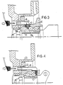
- Figures 3 and 4 are, respectively, schematic views in axial section of the bearing assembly of a vehicle wheel hub, said bearing having two alternative embodiments of an integrated current generator; and
- Figure 5 is a further schematic configuration of the bearing assembly according to the invention .
-
- Referring initially to the scheme of Figure 1,
numerals rotor 12 mounted on the bearingstationary ring 10, or as an alternative on the bearing support, and astator 13 fast to the rotatingring 11. - The generator can have different configurations for its components: the stator comprises necessarily a coil, while the rotor has an element suitable to generate electric pulses in the stator coil. As shown in the examples of Figures 3 and 4, the pulse generating element might be either a multipolar magnetised ring, facing the stator coil, or a toothed (or with openings) metallic ring facing a stator comprising a coil and a magnetised ring. In the example of Figure 3, the
rotor 12 comprises a toothed ring fixed to thestationary ring 10 of the bearing; thestator 13, comprising a coil 13a placed on the side of amagnetised ring 13b, is fixed to the change the magnetic flow through themagnetised ring 13b and coil 13a, and thus an alternate current is generated in the coil. - Referring again to the scheme of Figure 1, an alternate current is generated at the
coil 13 terminals having a frequency and an amplitude related to the rotating speed and to the generator features. The stator is connected to an AC/DC rectifier 14 which feeds direct current, through afeeding cable 15, to atransmitter 16, e.g. a radiofrequency transmitter, fast on tyre or on the tyre rim of the wheel. The transmitter is connected to one or more sensors 17, 18 which detect relevant data from the tyre, as for instance the pressure and/or the temperature, or the tread wear. Thetransmitter 16 transmits the data to a receiver (not shown) on board of the vehicle. - A connector 19 is preferably provided on the
feeding cable 15 to cut the connection when the bearing has to be disassembled from the wheel. - In the scheme of Figure 2, a configuration alternative to that of Figure 1. In said alternative, the
transmitter 16 is fitted in the bearing with thegenerator - The connecting cables 20, 21 are used just for transmitting the signals and not used for feeding purposes; also in this case one or more connectors 19 will preferably be provided in order to be able to remove the wheel from the bearing.
- The sensor might comprise temperature probes or thermocouples mounted on the brakes to transmit, at the same time, information to the receiver through a single multichannel transmission system.
- In a further alternative (not shown) of the schematic configuration of Figure 1, the rectifier 14 positioned between the generator and the transmitter will be integral with the transmitter on the wheel instead of being integral with the bearing.
- Figure 4 shows an application alternative to that of Figure 3. In Figure 4, the rotating
ring 11 of the bearing is the outer ring; the stator, comprising acoil 13, is mounted on said outer ring and the coil faces the rotor comprising a multipolarmagnetised ring 12 mounted on thestationary ring 10 of the bearing. In the lower part of the drawing there is thefeeding cable 15 which reaches the transmitter (not shown) mounted on the wheel through an opening 22 obtained in thedrum brake 23. - It should be noted that the output signal from the generator, before being rectified, is an alternate current electric signal which contains information relevant to the angular speed and acceleration of the wheel. As shown in a schematic way in Figure 5, the generated signal can be advantageously, directly transmitted to the transmitter through a separate cable 15a without being rectified, in order to transmit kinematic data to the receiver.
- Besides eliminating the disadvantages of the known art related to the use of batteries, the present invention eliminates all the cables currently provided on the ABS, ASR systems, therefore saving on weight, costs and achieving a better level of reliability.
- Further, the configuration of the invention allows the transmission, at the same time, of multiple information to the receiver on board of the vehicle through a single system of multichannel transmission: e.g. data relevant to the tyre pressure and temperature, tread wear, brake temperature, lateral and longitudinal accelerations.
- The invention is not limited by the embodiments herein described and illustrated, since such embodiments have to be considered as realisation examples of the bearing assembly, which is subject to changes of shape and of configuration, of structural and operational details. In particular, the invention can be used in sectors other than the automotive, generally wherever it is useful to obtain information concerning the rotating elements in order to control and/or monitor their operation.
Claims (16)
- A bearing assembly, particularly for a vehicle wheel hub, comprising a stationary part (10), a rotating part (11), and an integrated current generator (12, 13) in turn comprising a rotor (12) mounted on the stationary part (10) and a stator (13) .fixed to the rotating part (11) for loyally generating an electric current; the bearing assembly further comprising transmitter means (16) powered by said electric current and fast for rotation with said rotating part, and sensor means (17, 18) connected to the transmitter means and fitted to a member fixed for rotation with said rotating part (11); said transmitter means (16) transmitting information concerning the rotating parts. (11) to receiver means mounted to a non-rotating part, in particular fitted on board of the vehicle; the bearing assembly being characterised in that. the rotor (12) and the stator (13) are integral with the stationary part (10) and, respectively, with the rotating part (11.). of the bearing assembly.
- A bearing assembly as claimed in claim 1, characterised in that said transmitter means (16) are integral with said generator and are mounted onto the bearing.
- A bearing assembly as claimed in claim 1, characterised in that said transmitter means (16) are positioned on the vehicle wheel.
- A bearing assembly as claimed in claim 1,
characterised by comprising sensor means (17, 18) for detecting the pressure and temperature of the vehicle tyre, said sensor means being integrated with said transmitter means (16). - A bearing assembly as claimed in claim 1, characterised in that the generator generates a direct current for supplying said transmitter means (16) directly.
- A bearing assembly as claimed in claim 1, characterised in that the current generator (12, 13) is an alternate current generator connected to a current rectifier (14) positioned along the connection between the stator (13) and the transmitter means (16).
- A bearing assembly as claimed in claim 6, characterised in that the rectifier (14) is integral with the transmitter means and is mounted on the vehicle wheel.
- A bearing assembly as claimed in claim 1, characterised in that the rectifier (14) is integral with the stator which is mounted on the rotating part of the bearing.
- A bearing assembly as claimed in claim 1, characterised in that the sensor means comprise sensor means (17) of the temperature of the wheel tyre.
- A bearing assembly as claimed in claim 1, characterised in that the sensor means comprise sensor means (18) of the pressure of the wheel tyre.
- A bearing assembly as claimed in claim 1, characterised in that the sensor means comprise detecting means of the tread wear of the wheel tyre.
- A bearing assembly as claimed in claim 1, characterised in that the sensor means comprise sensor means of the temperature of the vehicle wheel brake.
- A bearing assembly as claimed in claim 1, characterised in that the output signal from the stator (13), besides being used to feed the transmitter means, is directly transmitted to the transmitter means (16) before being rectified, in order to transmit to the receiver means the kinematic data concerning the rotating parts.
- A bearing assembly as claimed in claim 1, characterised in that the rotor (12) comprises a toothed (or with openings) ring fixed to the stationary ring (10) of the bearing, and that the stator (13) comprises a coil (13a) placed on the side of a magnetised ring (13b) both fixed to the rotating ring (11) of the bearing.
- A bearing assembly as claimed in claim 1, characterised in that the rotor (12) comprises a multipolar magnetised ring mounted on the stationary ring (10) of the bearing, and that the stator comprises a coil (13) fixed to the rotating ring (11) of the bearing.
- A bearing assembly as claimed in claim 1, characterised in that the elements mounted on the vehicle wheel are electrically connected to the elements mounted on the bearing through one or more cables provided with one or more connectors (15).
Applications Claiming Priority (2)
| Application Number | Priority Date | Filing Date | Title |
|---|---|---|---|
| IT97TO000186 IT1291171B1 (en) | 1997-03-07 | 1997-03-07 | BEARING GROUP WITH INTEGRATED CURRENT GENERATOR. |
| ITTO970186 | 1997-03-07 |
Publications (2)
| Publication Number | Publication Date |
|---|---|
| EP0864450A1 EP0864450A1 (en) | 1998-09-16 |
| EP0864450B1 true EP0864450B1 (en) | 2003-05-28 |
Family
ID=11415483
Family Applications (1)
| Application Number | Title | Priority Date | Filing Date |
|---|---|---|---|
| EP19980103927 Expired - Lifetime EP0864450B1 (en) | 1997-03-07 | 1998-03-05 | A bearing assembly with an integrated current generator |
Country Status (3)
| Country | Link |
|---|---|
| EP (1) | EP0864450B1 (en) |
| DE (1) | DE69814951T2 (en) |
| IT (1) | IT1291171B1 (en) |
Families Citing this family (2)
| Publication number | Priority date | Publication date | Assignee | Title |
|---|---|---|---|---|
| DE202007017617U1 (en) * | 2007-12-14 | 2009-04-16 | PTG Pösges & Tigges GmbH | Tire pressure control system |
| CN109624618A (en) * | 2019-01-09 | 2019-04-16 | 湖北军缔悍隆科技发展有限公司 | A wired tire pressure transmission device |
Family Cites Families (9)
| Publication number | Priority date | Publication date | Assignee | Title |
|---|---|---|---|---|
| US4163208A (en) * | 1975-12-18 | 1979-07-31 | Merz Ernest J | Automatic wireless tire pressure monitoring system |
| US4300119A (en) * | 1979-09-06 | 1981-11-10 | Facet Enterprises, Inc. | Power generator for telemetry transmitter |
| FR2539679A1 (en) * | 1983-01-20 | 1984-07-27 | Renault Vehicules Ind | DEVICE FOR DETECTING THE UNDERFLANKING OF A TIRE AND MEASURING THE KINETIC CONDITION OF THE WHEEL OF A VEHICLE AND OF THE VEHICLE |
| DE3503347A1 (en) * | 1985-02-01 | 1986-08-14 | Dr.Ing.H.C. F. Porsche Ag, 7000 Stuttgart | DEVICE FOR WIRELESS MEASURING SIGNAL TRANSMISSION |
| FR2586622B2 (en) * | 1985-09-03 | 1987-11-13 | Labinal | DEFLATION DEVICE FOR VEHICLE TIRES |
| EP0365608A1 (en) * | 1988-02-26 | 1990-05-02 | Sondertechnik Gesellschaft m.b.H. | Device for controlling the air pressure in the tires of a vehicle |
| FR2669728B1 (en) * | 1990-11-28 | 1993-02-12 | Skf France | ACTIVE SENSOR DEVICE FOR MONITORING THE TIRE CONDITION OF A VEHICLE WHEEL AND MEASURING THE ROTATION CHARACTERISTICS OF THE WHEEL. |
| DE4125697A1 (en) * | 1991-08-02 | 1993-02-04 | Juergen Burghoff | Motor vehicle with contactless tyre air pressure monitoring device - has wheel mounted pressure sensor, and circuit for generating independent power source thus eliminating need for primary circuit frequency to be tuned to secondary circuit |
| FR2698421B1 (en) * | 1992-11-24 | 1995-06-02 | Skf France | Housing for radial fixing of a bearing. |
-
1997
- 1997-03-07 IT IT97TO000186 patent/IT1291171B1/en active IP Right Grant
-
1998
- 1998-03-05 EP EP19980103927 patent/EP0864450B1/en not_active Expired - Lifetime
- 1998-03-05 DE DE1998614951 patent/DE69814951T2/en not_active Expired - Lifetime
Also Published As
| Publication number | Publication date |
|---|---|
| DE69814951D1 (en) | 2003-07-03 |
| DE69814951T2 (en) | 2004-02-26 |
| ITTO970186A1 (en) | 1998-09-07 |
| EP0864450A1 (en) | 1998-09-16 |
| IT1291171B1 (en) | 1998-12-29 |
Similar Documents
| Publication | Publication Date | Title |
|---|---|---|
| US5583482A (en) | Device for monitoring tires with transmission of electric signals through the wheel disks | |
| CN100428285C (en) | Wireless sensor system and bearing unit with wireless sensors | |
| EP1308321B1 (en) | Brake device for vehicle | |
| EP1342633B1 (en) | Rotation detecting device and anti-skid braking system using the same | |
| JP4963006B2 (en) | Wireless sensor system and wheel bearing device with wireless sensor | |
| US6615954B2 (en) | Monitoring system and method for brake disks | |
| CN112278247B (en) | Aircraft wheel and brake assembly | |
| JP2010504247A (en) | In-tire multi-element piezoelectric sensor | |
| US7316159B2 (en) | Tire information detecting device | |
| EP0864450A1 (en) | A bearing assembly with an integrated current generator | |
| JP2006005978A (en) | Wireless sensor system and bearing device with wireless sensor | |
| JP2005100164A (en) | Wireless sensor system and bearing device with wireless sensor | |
| JP2001151090A (en) | Antilock braking system | |
| EP0235237A1 (en) | Electric power generator for supplying an electronic circuit | |
| JP2003157485A (en) | Signal transmission device indicating the state of the wheel support | |
| KR20180023862A (en) | Power supplying system for sensor mounted on the wheels of a vehicle using wireless power transfer | |
| WO2005029436A1 (en) | Wireless sensor system and wireless sensor-equipped bearing device | |
| JP3687385B2 (en) | Power generation device and tire internal pressure detection device using the same | |
| WO2019004062A1 (en) | In-wheel motor system and electric automobile | |
| JP2003148502A (en) | Remote control monitor system for wheel bearing device | |
| JP2003262646A (en) | Wireless rotation detector and radio switching device | |
| JP2003227843A (en) | Signal transmission device indicating the state of the vicinity of the wheel | |
| JP2005092555A (en) | Wireless sensor system and bearing device with wireless sensor | |
| JP2005304154A (en) | Rectenna and bearing device fitted with rectenna | |
| JPH05133962A (en) | Trouble shooting apparatus for wheel speed sensor signal system |
Legal Events
| Date | Code | Title | Description |
|---|---|---|---|
| PUAI | Public reference made under article 153(3) epc to a published international application that has entered the european phase |
Free format text: ORIGINAL CODE: 0009012 |
|
| AK | Designated contracting states |
Kind code of ref document: A1 Designated state(s): DE FR GB IT SE |
|
| AX | Request for extension of the european patent |
Free format text: AL;LT;LV;MK;RO;SI |
|
| 17P | Request for examination filed |
Effective date: 19981007 |
|
| AKX | Designation fees paid |
Free format text: DE FR GB IT SE |
|
| RBV | Designated contracting states (corrected) |
Designated state(s): DE FR GB IT SE |
|
| 17Q | First examination report despatched |
Effective date: 20020304 |
|
| GRAH | Despatch of communication of intention to grant a patent |
Free format text: ORIGINAL CODE: EPIDOS IGRA |
|
| GRAH | Despatch of communication of intention to grant a patent |
Free format text: ORIGINAL CODE: EPIDOS IGRA |
|
| GRAA | (expected) grant |
Free format text: ORIGINAL CODE: 0009210 |
|
| AK | Designated contracting states |
Designated state(s): DE FR GB IT SE |
|
| REG | Reference to a national code |
Ref country code: GB Ref legal event code: FG4D |
|
| REF | Corresponds to: |
Ref document number: 69814951 Country of ref document: DE Date of ref document: 20030703 Kind code of ref document: P |
|
| REG | Reference to a national code |
Ref country code: SE Ref legal event code: TRGR |
|
| ET | Fr: translation filed | ||
| PLBE | No opposition filed within time limit |
Free format text: ORIGINAL CODE: 0009261 |
|
| STAA | Information on the status of an ep patent application or granted ep patent |
Free format text: STATUS: NO OPPOSITION FILED WITHIN TIME LIMIT |
|
| 26N | No opposition filed |
Effective date: 20040302 |
|
| PGFP | Annual fee paid to national office [announced via postgrant information from national office to epo] |
Ref country code: GB Payment date: 20050302 Year of fee payment: 8 |
|
| PGFP | Annual fee paid to national office [announced via postgrant information from national office to epo] |
Ref country code: SE Payment date: 20050321 Year of fee payment: 8 Ref country code: FR Payment date: 20050321 Year of fee payment: 8 |
|
| PG25 | Lapsed in a contracting state [announced via postgrant information from national office to epo] |
Ref country code: GB Free format text: LAPSE BECAUSE OF NON-PAYMENT OF DUE FEES Effective date: 20060305 |
|
| PG25 | Lapsed in a contracting state [announced via postgrant information from national office to epo] |
Ref country code: SE Free format text: LAPSE BECAUSE OF NON-PAYMENT OF DUE FEES Effective date: 20060306 |
|
| EUG | Se: european patent has lapsed | ||
| GBPC | Gb: european patent ceased through non-payment of renewal fee |
Effective date: 20060305 |
|
| REG | Reference to a national code |
Ref country code: FR Ref legal event code: ST Effective date: 20061130 |
|
| PG25 | Lapsed in a contracting state [announced via postgrant information from national office to epo] |
Ref country code: FR Free format text: LAPSE BECAUSE OF NON-PAYMENT OF DUE FEES Effective date: 20060331 |
|
| PGFP | Annual fee paid to national office [announced via postgrant information from national office to epo] |
Ref country code: IT Payment date: 20150326 Year of fee payment: 18 |
|
| PGFP | Annual fee paid to national office [announced via postgrant information from national office to epo] |
Ref country code: DE Payment date: 20150601 Year of fee payment: 18 |
|
| REG | Reference to a national code |
Ref country code: DE Ref legal event code: R119 Ref document number: 69814951 Country of ref document: DE |
|
| PG25 | Lapsed in a contracting state [announced via postgrant information from national office to epo] |
Ref country code: DE Free format text: LAPSE BECAUSE OF NON-PAYMENT OF DUE FEES Effective date: 20161001 |
|
| PG25 | Lapsed in a contracting state [announced via postgrant information from national office to epo] |
Ref country code: IT Free format text: LAPSE BECAUSE OF NON-PAYMENT OF DUE FEES Effective date: 20160305 |