EP0863560A2 - Method of bonding plastic hydrophobic film to metallic sheet and a bipolar rechargeable battery - Google Patents
Method of bonding plastic hydrophobic film to metallic sheet and a bipolar rechargeable battery Download PDFInfo
- Publication number
- EP0863560A2 EP0863560A2 EP98301543A EP98301543A EP0863560A2 EP 0863560 A2 EP0863560 A2 EP 0863560A2 EP 98301543 A EP98301543 A EP 98301543A EP 98301543 A EP98301543 A EP 98301543A EP 0863560 A2 EP0863560 A2 EP 0863560A2
- Authority
- EP
- European Patent Office
- Prior art keywords
- sheet member
- metallic sheet
- films
- gas
- bipolar
- Prior art date
- Legal status (The legal status is an assumption and is not a legal conclusion. Google has not performed a legal analysis and makes no representation as to the accuracy of the status listed.)
- Withdrawn
Links
Images


Classifications
-
- B—PERFORMING OPERATIONS; TRANSPORTING
- B29—WORKING OF PLASTICS; WORKING OF SUBSTANCES IN A PLASTIC STATE IN GENERAL
- B29C—SHAPING OR JOINING OF PLASTICS; SHAPING OF MATERIAL IN A PLASTIC STATE, NOT OTHERWISE PROVIDED FOR; AFTER-TREATMENT OF THE SHAPED PRODUCTS, e.g. REPAIRING
- B29C66/00—General aspects of processes or apparatus for joining preformed parts
- B29C66/70—General aspects of processes or apparatus for joining preformed parts characterised by the composition, physical properties or the structure of the material of the parts to be joined; Joining with non-plastics material
- B29C66/74—Joining plastics material to non-plastics material
- B29C66/742—Joining plastics material to non-plastics material to metals or their alloys
-
- B—PERFORMING OPERATIONS; TRANSPORTING
- B29—WORKING OF PLASTICS; WORKING OF SUBSTANCES IN A PLASTIC STATE IN GENERAL
- B29C—SHAPING OR JOINING OF PLASTICS; SHAPING OF MATERIAL IN A PLASTIC STATE, NOT OTHERWISE PROVIDED FOR; AFTER-TREATMENT OF THE SHAPED PRODUCTS, e.g. REPAIRING
- B29C37/00—Component parts, details, accessories or auxiliary operations, not covered by group B29C33/00 or B29C35/00
- B29C37/0078—Measures or configurations for obtaining anchoring effects in the contact areas between layers
- B29C37/0082—Mechanical anchoring
- B29C37/0085—Mechanical anchoring by means of openings in the layers
-
- B—PERFORMING OPERATIONS; TRANSPORTING
- B29—WORKING OF PLASTICS; WORKING OF SUBSTANCES IN A PLASTIC STATE IN GENERAL
- B29C—SHAPING OR JOINING OF PLASTICS; SHAPING OF MATERIAL IN A PLASTIC STATE, NOT OTHERWISE PROVIDED FOR; AFTER-TREATMENT OF THE SHAPED PRODUCTS, e.g. REPAIRING
- B29C63/00—Lining or sheathing, i.e. applying preformed layers or sheathings of plastics; Apparatus therefor
- B29C63/0026—Lining or sheathing, i.e. applying preformed layers or sheathings of plastics; Apparatus therefor an edge face with strip material, e.g. a panel edge
-
- B—PERFORMING OPERATIONS; TRANSPORTING
- B29—WORKING OF PLASTICS; WORKING OF SUBSTANCES IN A PLASTIC STATE IN GENERAL
- B29C—SHAPING OR JOINING OF PLASTICS; SHAPING OF MATERIAL IN A PLASTIC STATE, NOT OTHERWISE PROVIDED FOR; AFTER-TREATMENT OF THE SHAPED PRODUCTS, e.g. REPAIRING
- B29C65/00—Joining or sealing of preformed parts, e.g. welding of plastics materials; Apparatus therefor
- B29C65/02—Joining or sealing of preformed parts, e.g. welding of plastics materials; Apparatus therefor by heating, with or without pressure
-
- B—PERFORMING OPERATIONS; TRANSPORTING
- B29—WORKING OF PLASTICS; WORKING OF SUBSTANCES IN A PLASTIC STATE IN GENERAL
- B29C—SHAPING OR JOINING OF PLASTICS; SHAPING OF MATERIAL IN A PLASTIC STATE, NOT OTHERWISE PROVIDED FOR; AFTER-TREATMENT OF THE SHAPED PRODUCTS, e.g. REPAIRING
- B29C66/00—General aspects of processes or apparatus for joining preformed parts
- B29C66/01—General aspects dealing with the joint area or with the area to be joined
- B29C66/05—Particular design of joint configurations
- B29C66/10—Particular design of joint configurations particular design of the joint cross-sections
- B29C66/11—Joint cross-sections comprising a single joint-segment, i.e. one of the parts to be joined comprising a single joint-segment in the joint cross-section
- B29C66/112—Single lapped joints
- B29C66/1122—Single lap to lap joints, i.e. overlap joints
-
- B—PERFORMING OPERATIONS; TRANSPORTING
- B29—WORKING OF PLASTICS; WORKING OF SUBSTANCES IN A PLASTIC STATE IN GENERAL
- B29C—SHAPING OR JOINING OF PLASTICS; SHAPING OF MATERIAL IN A PLASTIC STATE, NOT OTHERWISE PROVIDED FOR; AFTER-TREATMENT OF THE SHAPED PRODUCTS, e.g. REPAIRING
- B29C66/00—General aspects of processes or apparatus for joining preformed parts
- B29C66/01—General aspects dealing with the joint area or with the area to be joined
- B29C66/05—Particular design of joint configurations
- B29C66/304—Joining through openings in an intermediate part of the article
-
- B—PERFORMING OPERATIONS; TRANSPORTING
- B29—WORKING OF PLASTICS; WORKING OF SUBSTANCES IN A PLASTIC STATE IN GENERAL
- B29C—SHAPING OR JOINING OF PLASTICS; SHAPING OF MATERIAL IN A PLASTIC STATE, NOT OTHERWISE PROVIDED FOR; AFTER-TREATMENT OF THE SHAPED PRODUCTS, e.g. REPAIRING
- B29C66/00—General aspects of processes or apparatus for joining preformed parts
- B29C66/40—General aspects of joining substantially flat articles, e.g. plates, sheets or web-like materials; Making flat seams in tubular or hollow articles; Joining single elements to substantially flat surfaces
- B29C66/41—Joining substantially flat articles ; Making flat seams in tubular or hollow articles
- B29C66/43—Joining a relatively small portion of the surface of said articles
- B29C66/433—Casing-in, i.e. enclosing an element between two sheets by an outlined seam
-
- B—PERFORMING OPERATIONS; TRANSPORTING
- B29—WORKING OF PLASTICS; WORKING OF SUBSTANCES IN A PLASTIC STATE IN GENERAL
- B29C—SHAPING OR JOINING OF PLASTICS; SHAPING OF MATERIAL IN A PLASTIC STATE, NOT OTHERWISE PROVIDED FOR; AFTER-TREATMENT OF THE SHAPED PRODUCTS, e.g. REPAIRING
- B29C66/00—General aspects of processes or apparatus for joining preformed parts
- B29C66/50—General aspects of joining tubular articles; General aspects of joining long products, i.e. bars or profiled elements; General aspects of joining single elements to tubular articles, hollow articles or bars; General aspects of joining several hollow-preforms to form hollow or tubular articles
- B29C66/51—Joining tubular articles, profiled elements or bars; Joining single elements to tubular articles, hollow articles or bars; Joining several hollow-preforms to form hollow or tubular articles
- B29C66/53—Joining single elements to tubular articles, hollow articles or bars
- B29C66/532—Joining single elements to the wall of tubular articles, hollow articles or bars
- B29C66/5326—Joining single elements to the wall of tubular articles, hollow articles or bars said single elements being substantially flat
-
- B—PERFORMING OPERATIONS; TRANSPORTING
- B29—WORKING OF PLASTICS; WORKING OF SUBSTANCES IN A PLASTIC STATE IN GENERAL
- B29C—SHAPING OR JOINING OF PLASTICS; SHAPING OF MATERIAL IN A PLASTIC STATE, NOT OTHERWISE PROVIDED FOR; AFTER-TREATMENT OF THE SHAPED PRODUCTS, e.g. REPAIRING
- B29C66/00—General aspects of processes or apparatus for joining preformed parts
- B29C66/50—General aspects of joining tubular articles; General aspects of joining long products, i.e. bars or profiled elements; General aspects of joining single elements to tubular articles, hollow articles or bars; General aspects of joining several hollow-preforms to form hollow or tubular articles
- B29C66/61—Joining from or joining on the inside
-
- B—PERFORMING OPERATIONS; TRANSPORTING
- B29—WORKING OF PLASTICS; WORKING OF SUBSTANCES IN A PLASTIC STATE IN GENERAL
- B29C—SHAPING OR JOINING OF PLASTICS; SHAPING OF MATERIAL IN A PLASTIC STATE, NOT OTHERWISE PROVIDED FOR; AFTER-TREATMENT OF THE SHAPED PRODUCTS, e.g. REPAIRING
- B29C66/00—General aspects of processes or apparatus for joining preformed parts
- B29C66/70—General aspects of processes or apparatus for joining preformed parts characterised by the composition, physical properties or the structure of the material of the parts to be joined; Joining with non-plastics material
- B29C66/71—General aspects of processes or apparatus for joining preformed parts characterised by the composition, physical properties or the structure of the material of the parts to be joined; Joining with non-plastics material characterised by the composition of the plastics material of the parts to be joined
-
- B—PERFORMING OPERATIONS; TRANSPORTING
- B29—WORKING OF PLASTICS; WORKING OF SUBSTANCES IN A PLASTIC STATE IN GENERAL
- B29C—SHAPING OR JOINING OF PLASTICS; SHAPING OF MATERIAL IN A PLASTIC STATE, NOT OTHERWISE PROVIDED FOR; AFTER-TREATMENT OF THE SHAPED PRODUCTS, e.g. REPAIRING
- B29C66/00—General aspects of processes or apparatus for joining preformed parts
- B29C66/70—General aspects of processes or apparatus for joining preformed parts characterised by the composition, physical properties or the structure of the material of the parts to be joined; Joining with non-plastics material
- B29C66/73—General aspects of processes or apparatus for joining preformed parts characterised by the composition, physical properties or the structure of the material of the parts to be joined; Joining with non-plastics material characterised by the intensive physical properties of the material of the parts to be joined, by the optical properties of the material of the parts to be joined, by the extensive physical properties of the parts to be joined, by the state of the material of the parts to be joined or by the material of the parts to be joined being a thermoplastic or a thermoset
- B29C66/731—General aspects of processes or apparatus for joining preformed parts characterised by the composition, physical properties or the structure of the material of the parts to be joined; Joining with non-plastics material characterised by the intensive physical properties of the material of the parts to be joined, by the optical properties of the material of the parts to be joined, by the extensive physical properties of the parts to be joined, by the state of the material of the parts to be joined or by the material of the parts to be joined being a thermoplastic or a thermoset characterised by the intensive physical properties of the material of the parts to be joined
- B29C66/7311—Thermal properties
- B29C66/73111—Thermal expansion coefficient
- B29C66/73112—Thermal expansion coefficient of different thermal expansion coefficient, i.e. the thermal expansion coefficient of one of the parts to be joined being different from the thermal expansion coefficient of the other part
-
- H—ELECTRICITY
- H01—ELECTRIC ELEMENTS
- H01M—PROCESSES OR MEANS, e.g. BATTERIES, FOR THE DIRECT CONVERSION OF CHEMICAL ENERGY INTO ELECTRICAL ENERGY
- H01M10/00—Secondary cells; Manufacture thereof
- H01M10/04—Construction or manufacture in general
- H01M10/0413—Large-sized flat cells or batteries for motive or stationary systems with plate-like electrodes
- H01M10/0418—Large-sized flat cells or batteries for motive or stationary systems with plate-like electrodes with bipolar electrodes
-
- H—ELECTRICITY
- H01—ELECTRIC ELEMENTS
- H01M—PROCESSES OR MEANS, e.g. BATTERIES, FOR THE DIRECT CONVERSION OF CHEMICAL ENERGY INTO ELECTRICAL ENERGY
- H01M10/00—Secondary cells; Manufacture thereof
- H01M10/34—Gastight accumulators
- H01M10/345—Gastight metal hydride accumulators
-
- H—ELECTRICITY
- H01—ELECTRIC ELEMENTS
- H01M—PROCESSES OR MEANS, e.g. BATTERIES, FOR THE DIRECT CONVERSION OF CHEMICAL ENERGY INTO ELECTRICAL ENERGY
- H01M4/00—Electrodes
- H01M4/02—Electrodes composed of, or comprising, active material
-
- B—PERFORMING OPERATIONS; TRANSPORTING
- B29—WORKING OF PLASTICS; WORKING OF SUBSTANCES IN A PLASTIC STATE IN GENERAL
- B29K—INDEXING SCHEME ASSOCIATED WITH SUBCLASSES B29B, B29C OR B29D, RELATING TO MOULDING MATERIALS OR TO MATERIALS FOR MOULDS, REINFORCEMENTS, FILLERS OR PREFORMED PARTS, e.g. INSERTS
- B29K2027/00—Use of polyvinylhalogenides or derivatives thereof as moulding material
- B29K2027/12—Use of polyvinylhalogenides or derivatives thereof as moulding material containing fluorine
- B29K2027/18—PTFE, i.e. polytetrafluorethene, e.g. ePTFE, i.e. expanded polytetrafluorethene
-
- B—PERFORMING OPERATIONS; TRANSPORTING
- B29—WORKING OF PLASTICS; WORKING OF SUBSTANCES IN A PLASTIC STATE IN GENERAL
- B29L—INDEXING SCHEME ASSOCIATED WITH SUBCLASS B29C, RELATING TO PARTICULAR ARTICLES
- B29L2031/00—Other particular articles
- B29L2031/34—Electrical apparatus, e.g. sparking plugs or parts thereof
- B29L2031/3468—Batteries, accumulators or fuel cells
-
- B—PERFORMING OPERATIONS; TRANSPORTING
- B29—WORKING OF PLASTICS; WORKING OF SUBSTANCES IN A PLASTIC STATE IN GENERAL
- B29L—INDEXING SCHEME ASSOCIATED WITH SUBCLASS B29C, RELATING TO PARTICULAR ARTICLES
- B29L2031/00—Other particular articles
- B29L2031/737—Articles provided with holes, e.g. grids, sieves
-
- H—ELECTRICITY
- H01—ELECTRIC ELEMENTS
- H01M—PROCESSES OR MEANS, e.g. BATTERIES, FOR THE DIRECT CONVERSION OF CHEMICAL ENERGY INTO ELECTRICAL ENERGY
- H01M12/00—Hybrid cells; Manufacture thereof
- H01M12/08—Hybrid cells; Manufacture thereof composed of a half-cell of a fuel-cell type and a half-cell of the secondary-cell type
-
- H—ELECTRICITY
- H01—ELECTRIC ELEMENTS
- H01M—PROCESSES OR MEANS, e.g. BATTERIES, FOR THE DIRECT CONVERSION OF CHEMICAL ENERGY INTO ELECTRICAL ENERGY
- H01M8/00—Fuel cells; Manufacture thereof
- H01M8/02—Details
- H01M8/0271—Sealing or supporting means around electrodes, matrices or membranes
-
- Y—GENERAL TAGGING OF NEW TECHNOLOGICAL DEVELOPMENTS; GENERAL TAGGING OF CROSS-SECTIONAL TECHNOLOGIES SPANNING OVER SEVERAL SECTIONS OF THE IPC; TECHNICAL SUBJECTS COVERED BY FORMER USPC CROSS-REFERENCE ART COLLECTIONS [XRACs] AND DIGESTS
- Y02—TECHNOLOGIES OR APPLICATIONS FOR MITIGATION OR ADAPTATION AGAINST CLIMATE CHANGE
- Y02E—REDUCTION OF GREENHOUSE GAS [GHG] EMISSIONS, RELATED TO ENERGY GENERATION, TRANSMISSION OR DISTRIBUTION
- Y02E60/00—Enabling technologies; Technologies with a potential or indirect contribution to GHG emissions mitigation
- Y02E60/10—Energy storage using batteries
-
- Y—GENERAL TAGGING OF NEW TECHNOLOGICAL DEVELOPMENTS; GENERAL TAGGING OF CROSS-SECTIONAL TECHNOLOGIES SPANNING OVER SEVERAL SECTIONS OF THE IPC; TECHNICAL SUBJECTS COVERED BY FORMER USPC CROSS-REFERENCE ART COLLECTIONS [XRACs] AND DIGESTS
- Y02—TECHNOLOGIES OR APPLICATIONS FOR MITIGATION OR ADAPTATION AGAINST CLIMATE CHANGE
- Y02E—REDUCTION OF GREENHOUSE GAS [GHG] EMISSIONS, RELATED TO ENERGY GENERATION, TRANSMISSION OR DISTRIBUTION
- Y02E60/00—Enabling technologies; Technologies with a potential or indirect contribution to GHG emissions mitigation
- Y02E60/30—Hydrogen technology
- Y02E60/50—Fuel cells
-
- Y—GENERAL TAGGING OF NEW TECHNOLOGICAL DEVELOPMENTS; GENERAL TAGGING OF CROSS-SECTIONAL TECHNOLOGIES SPANNING OVER SEVERAL SECTIONS OF THE IPC; TECHNICAL SUBJECTS COVERED BY FORMER USPC CROSS-REFERENCE ART COLLECTIONS [XRACs] AND DIGESTS
- Y02—TECHNOLOGIES OR APPLICATIONS FOR MITIGATION OR ADAPTATION AGAINST CLIMATE CHANGE
- Y02P—CLIMATE CHANGE MITIGATION TECHNOLOGIES IN THE PRODUCTION OR PROCESSING OF GOODS
- Y02P70/00—Climate change mitigation technologies in the production process for final industrial or consumer products
- Y02P70/50—Manufacturing or production processes characterised by the final manufactured product
Definitions
- the present invention relates to a method of bonding a plastic hydrophobic film to a metallic sheet member and to an article so produced.
- the invention is of particular benefit for a bipolar cell for gas depolarized rechargeable batteries such as nickel hydrogen and zinc oxygen the construction of which is within the ambit of this invention.
- Bipolar batteries require a conductive planar layer between series connected cells which replaces external bus bars employed in monopolar batteries. Bipolar batteries also require a means for restricting electrolyte communication between series connected cells as this completes an intrinsic short circuit when combined with the bipolar plate.
- this restriction is accomplished by applying an inert hydrophobic electrically insulating layer to the periphery of the bipolar plate to contain liquid electrolyte solution within the confines of the individual cell.
- a preferred material for this purpose is polytetrafluoroethylene, for example, available under the trademark Teflon®, manufactured by E.I. duPont de Nemours Company of Wilmington, DE.
- the hydrophobic film must be bonded to the metal in order to prevent electrolyte from creeping under the layer and thereby bridging to the next series cell.
- the bonding between the Teflon® material and the bipolar plate must be stable in the cell environment as an unstable bond will eventually delaminate leading to an intercell electrolyte solution bridge.
- traditional Teflon® coating processes such as those with carbon and chromic oxide primers have not been found to be stable in the cell environment. Chemically applied coatings typically fail due to attack on the bonding interface between the Teflon® material and the metallic bipolar plate in the cell electrochemical environment.
- a method of bonding a plastic hydrophobic film to a metallic sheet member comprising the steps of:
- the invention may be carried out in that plastic hydrophobic material is bonded to a metallic sheet member such that the resulting sandwich structure is impervious to electrochemical delamination.
- First and second films of the plastic hydrophobic material are applied to opposed surfaces of the metallic sheet member and extend beyond a peripheral edge of the metallic sheet member to form contiguous border portions.
- a plurality of perforations are formed through the metallic sheet member at locations spaced from its peripheral edge.
- a resulting sandwich structure of the metallic sheet member and the first and second films are compressed and simultaneously the temperature is raised to the sintering temperature of the hydrophobic film material.
- the first and second films are caused to melt sufficiently at their interfaces to cause an intermixing of the juxtaposed material thereof throughout the region of the border portions and throughout the regions of the perforations.
- the films When the resulting sandwich structure is cooled to room temperature and the films return to the hardened state, they are firmly bonded together in the region of the border to form an integral fringe which seals the peripheral edge of the metallic sheet member from ambient conditions and throughout the regions of the perforations such that the first and second films, respectively, are drawn firmly into engagement with the metallic sheet member by reason of the differential coefficient of thermal expansion between the metallic sheet member and the hydrophobic film material.
- films of the plastic hydrophobic material, Teflon®, for example, on opposite sides of a conductive bipolar plate, nickel, for example, are thermally welded to each other through perforations at the edge of the bipolar plate.
- the films are riveted to the bipolar plate.
- the welding may be carried out by compressing a sandwich of the two films and the bipolar plate in a heating press and raising the temperature to the sintering point of the film material (typically less than approximately 400°C) which must be less then the melting point of the bipolar plate (for example, 1455°C for nickel).
- the films are truncated conical surfaces which are bonded to the inner and outer perforated conical surface of a metallic bipolar dish as taught in the aforementioned U.S. Application Serial No. 08/626,992.
- the differential coefficient of thermal expansion of the Teflon® material causes the outer layer to compress against the metallic surface.
- the inner Teflon® layer is prevented from pulling away from the metallic dish by the numerous rivet points through the dish to the outer Teflon® layer.
- the invention provides a method in which inert plastic hydrophobic film material is bonded to a metallic sheet member such that the resulting sandwich structure is impervious to electrochemical delamination and an article produced by such a method.
- the metallic sheet member may comprise nickel and the plastic hydrophobic film may comprise polytetrafluoroethylene.
- a bipolar rechargeable battery comprising a metallic bipolar cup having a base and an integral upstanding side wall encompassing the base, the upstanding sidewall having first and second opposed surfaces and a peripheral edge and a plurality of perforations therethrough at locations spaced from the peripheral edge, an insulating material covering the upstanding side wall including a first film of plastic hydrophobic material contiguous with the first surface thereof and extending beyond the peripheral edge of the upstanding sidewall to form a first border portion and including a second film of plastic hydrophobic material contiguous with the second surface of the metallic sheet member and extending beyond the peripheral edge of the upstanding sidewall to form a second border portion contiguous with the first border portion, the first and second films being bonded together under heat and pressure at the first and second border portions to form a solid fringe sealing the edge from ambient conditions, the first and second films being firmly bonded together throughout the regions of the perforations such that the first and second films, respectively, are drawn firmly into engagement with the side wall by reason of
- the battery may comprise a vessel having an inner surface defining an interior region for bulk gas storage, a plurality of cells mounted within said vessel in a nested relationship, each cell containing a metered predetermined quantity of electrolyte, each of the cells including a condensed phase electrode proximate the base, a gas electrode including a condensed current collector for a gaseous active material, and a dielectric separator between the condensed phase electrode and said gas electrode, the upstanding side wall of each of the plurality of cells being oriented to enable gas passage from each of the cells to the bulk gas region within the battery.
- the invention enables the provision of an improved bipolar cell for gas depolarized rechargeable batteries such as nickel hydrogen and zinc oxygen wherein the bipolar plate is constructed in accordance with the foregoing.
- a bipolar electrode structure based on a conductive cup with insulated hydrophobic conical side walls may be provided, as described above, which act to insulate the cup from adjacent cups to impede the exchange of electrolyte solution between cells.
- Such a bipolar battery with conical or cup-shaped electrodes may be assembled in a nested fashion.
- the metallic cup is preferably nickel although titanium may be used, and the insulator is, for example, a hydrophobic insulator such as Teflon®.
- Fig. 1 illustrates a conventional monopolar battery 120 with adjoining cells 122, 124, each with a positive electrode 126 and a negative electrode 128.
- an external bus bar 130 connects the negative electrode 128 of the cell 122 and the positive electrode 126 of the cell 124.
- a conductive planar layer 134 replaces the bus bar 130 and is positioned between adjoining cells 136, 138 and is so constructed in the manner taught in the aforementioned application, Serial No. 08/626,992 to contain liquid electrolyte solution within the confines of each individual cell.
- the present invention is an improvement on the construction of that earlier construction of battery.
- Fig. 3 illustrates a bipolar rechargeable battery 20 embodying the invention disclosed in the aforementioned application, likely of the bipolar nickel hydrogen variety.
- a vessel for the battery is defined by a central cylinder 22 which may be coated with a Teflon® liner 24.
- a plurality of cells 36 are suitably mounted within the central cylinder 22 in a nested relationship.
- Each cell 36 contains a metered predetermined quantity of electrolyte and includes a metallic bipolar cup 38 having a base 40 and an integral upstanding side wall 42 encompassing the base.
- the upstanding side wall is of truncated conical shape diverging with increased distance from the base (see Fig. 4), although other shapes are within the scope of the present invention including the side wall 42 being substantially coplanar with the base 40.
- An insulating material 44 covers the upstanding side wall 42.
- the metallic bipolar cup 38 may be fabricated from a variety of materials including nickel, aluminum plated with nickel, stainless steel, metallic coated graphite composite and titanium.
- a preferred side wall coating is a hydrophobic fluorocarbon such as polytetrafluoroethylene, most notably, that material sold under the trademark Teflon® by E.I. duPont de Nemours Company of Wilmington, DE.
- a condensed phase electrode 46 is positioned proximate the base.
- the condensed phase electrodes used for the purposes of the present invention are typically 84% porous 0.1 cm thick sintered nickel supported on a nickel screen and electrochemically loaded to between 1.0 and 2.5 g/cm 3 of void volume with active Ni(OH) 2 .
- This is a standard aerospace positive electrode although it is understood that a variety of nickel positive electrodes could be employed.
- a sintered nickel electrode without a support screen would be preferred as the screen is not needed for current conduction in a bipolar battery.
- a gas electrode 48 including a condensed current collector for a gaseous active material.
- the gas electrode is typically platinum powder or platinized carbon powder bonded with Teflon® and supported on carbon cloth or expanded metal.
- the gas electrode must be conductive through its thickness and, to this end, has no hydrophobic wet proofing porous Teflon® layer. Back side hydrophobicity is still required in order that the electrolyte does not flood and block a gas screen 50, to be described. This is achieved by the vendor of the gas electrode 48 using a proprietary hydrophobic carbon coating on the gas side of the electrode.
- the gas electrode 48 is a solid current collector for a gaseous active material and is sized to fittingly engage the side wall 42 such that any gas generated at the condensed phase electrode 46 must pass through the gas electrode to escape the cell 36 to thereby recombine the generated gas with the active material gas within the cell.
- a dielectric separator 50 Intermediate the gas electrode 48 and the condensed phase electrode 46 is a dielectric separator 50.
- One form of the separator employed for purposes of the invention is ZrO 2 woven cloth approximately 80% porous and 0.05 cm thick. However, other suitable materials could be used to achieve a similar result.
- the separator acts to electrically insulate the opposing electrodes but allows ionic conduction between the electrodes via the liquid electrolyte which fills the pores of the separator.
- the upstanding side walls 42 of adjacent cells 36 are oriented such that they mutually define a gap 52 enabling gas communication between the adjacent cells and between each of the cells and the interior bulk gas region 34 within the battery 20.
- an insulating liner 24 is provided on the inner surface of the vessel for assuring its fluid integrity.
- the gas screen 54 may be any porous conductive inert material such as nickel screen, porous nickel felt, nickel coated plastic screen, and the like. It serves the purpose of allowing shared H 2 access to the entire face of the gas electrode and provides electrical conductivity between adjacent cells.
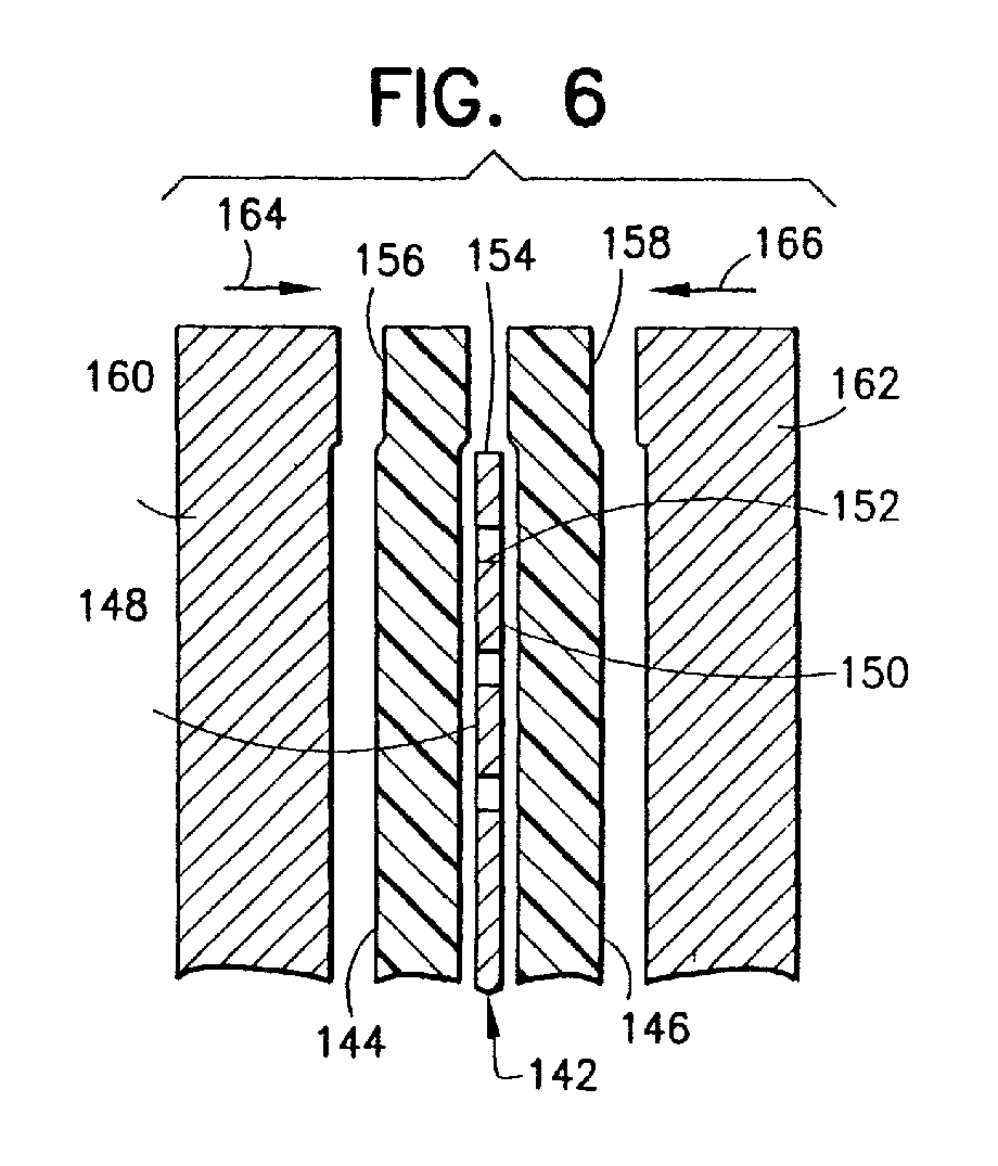
- the present invention has particular application in the manufacture of the bipolar cup 38 and, more specifically, of the upstanding wall 42 thereof. Still more specifically, the invention relates to the manner of bonding an inert plastic hydrophobic film material represented by first and second films 144, 146 to opposed surfaces 148, 150 of a metallic sheet member 142.
- the plastic hydrophobic films 144, 146 are of a hydrophobic fluorocarbon such as polytetrafluoroethylene, most notably, that material sold under the trademark Teflon® by E.I. duPont de Nemours Company of Wilmington, DE.
- the metallic sheet member 142 may be of any suitable metal but if for use in a bipolar rechargeable battery, nickel would be preferred. In keeping with the invention, the metallic sheet member 142 is formed with a plurality of perforations 152 through the metallic sheet member at locations spaced from a peripheral edge 154 thereof.
- the first film 144 is positioned contiguous with the first surface 148 of the metallic sheet member 142 such that a first border portion 156 extends beyond the peripheral edge 154 of the metallic sheet member.
- the second film 146 is positioned contiguous with the second surface 150 of the metallic sheet member 142 such that a second border portion 158 extends beyond the peripheral edge 154 of the metallic sheet member contiguous with the first border portion.
- opposed dies 160, 162 which are suitably formed are advanced, respectively, in the directions of arrows 164, 166 and compressed onto a resulting sandwich structure of the metallic sheet member 142 and the first and second films 144, 146 of the plastic hydrophobic material.
- the temperature of the resulting sandwich structure is raised to the sintering temperature of the plastic hydrophobic material until the first and second films 144, 146 are caused to melt sufficiently at their interfaces to cause an intermixing of the juxtaposed material thereof throughout the region of the border portions 156, 158 and throughout the regions of the perforations 152.
- the sintering temperature is typically less than 400°C and much less than the melting point of the metallic sheet member which, for nickel, would be 1455 c .
- the resulting sandwich structure is cooled to room temperature at which the first and second films 144, 146 return to a hardened state such that in the region of the border portions 156, 158 are firmly bonded together to form an integral fringe 168 which seals the peripheral edge 154 of the metallic sheet member 142 from ambient conditions. Additionally, throughout the regions of the perforations 152, the first and second films 144, 146 are firmly bonded together such that the first and second films, respectively, are drawn firmly into engagement with the metallic sheet member by reason of the differential coefficient of thermal expansion between the metallic sheet member and the plastic hydrophobic material.
- the resulting sandwich structure is impervious to electrochemical delamination.
- a chemically bonded Teflon® layer is usually found to be delaminated during post test examination. Such delamination is never found on batteries built with the above approach.
- battery BPNH50 a 4 cell 5" diameter battery was assembled with Ni(OH) 2 electrodes, ZrO 2 felt separators, PT catalyzed negative electrode, carbon cloth gas screens and a 38% KOH, 1.5% LiOH in water electrolyte solution.
- the bipolar plates for this battery are composed of 0.001" thick nickel metallic cups with three rows of 0.05" diameter perforations on 0.100" centers etched in the side walls of the nickel disk.
- 0.005" thick Teflon® films are welded to the inner and outer conical surfaces as described in this disclosure. The resultant battery has operated through 18 cycles without any evidence of intercell electrolyte leakage.
Landscapes
- Engineering & Computer Science (AREA)
- Mechanical Engineering (AREA)
- Chemical Kinetics & Catalysis (AREA)
- Chemical & Material Sciences (AREA)
- Electrochemistry (AREA)
- General Chemical & Material Sciences (AREA)
- Manufacturing & Machinery (AREA)
- Physics & Mathematics (AREA)
- Thermal Sciences (AREA)
- Secondary Cells (AREA)
- Sealing Battery Cases Or Jackets (AREA)
- Hybrid Cells (AREA)
- Cell Electrode Carriers And Collectors (AREA)
- Laminated Bodies (AREA)
- Battery Electrode And Active Subsutance (AREA)
Abstract
Description
whereby the resulting sandwich structure is impervious to electrochemical delamination.
Claims (10)
- A method of bonding a plastic hydrophobic film to a metallic sheet member comprising the steps of:(a) forming a plurality of perforations through the metallic sheet member at locations spaced from a peripheral edge thereof, the metallic sheet member having first and second opposed surfaces;(b) applying a first film of plastic hydrophobic material contiguous with the first surface of the metallic sheet member and extending beyond the peripheral page of the metallic sheet member to form a first border portion;(c) applying a second film of plastic hydrophobic material contiguous with the second surface of the metallic sheet member and extending beyond the peripheral edge of the metallic sheet member to form a second border portion contiguous with the first border portion;(d) compressing together a resulting sandwich structure of the metallic sheet member and the first and second layers of the plastic hydrophobic material; and(e) simultaneously with step (d), raising the temperature of the resulting sandwich structure to the sintering temperature of the plastic hydrophobic material until the first and second films are caused to melt sufficiently at their interfaces to cause an intermixing of the juxtaposed material thereof throughout the region of the border portions and throughout the regions of the perforations; and(f) cooling the resulting sandwich structure to room temperature at which the first and second films of the plastic hydrophobic material return to a hardened state such that the first and second films in the region of the border portions are firmly bonded together to form an integral fringe which seals the peripheral edge of the metallic sheet member from ambient conditions and such that throughout the regions of the perforations the first and second films are firmly bonded together and such that the first and second films, respectively, are drawn firmly into engagement with the metallic sheet member by reason of She differential coefficient of thermal expansion between the metallic sheet member and the plastic hydrophobic material;
whereby the resulting sandwich structure is impervious to electrochemical delamination. - A method as claimed in claim 1 wherein the metallic sheet member comprises nickel and the plastic hydrophobic film comprises polytetrafluoroethylene.
- A bipolar rechargeable battery comprising a metallic bipolar cup (38) having a base (40) and an integral upstanding side wall (42) encompassing the base, the upstanding sidewall having first and second opposed surfaces (248, 150) and a peripheral edge (154) and a plurality of perforations (152) therethrough at locations spaced from the peripheral edge (154), an insulating material (44) covering the upstanding side wall (42) including a first film (144) of plastic hydrophobic material contiguous with the first surface (148) thereof and extending beyond the peripheral edge (154) of the upstanding sidewall (42) to form a first border portion (156) and including a second film (146) of plastic hydrophobic material contiguous with the second surface (150) of the metallic sheet member (38) and extending beyond the peripheral edge of the upstanding sidewall (42) to form a second border portion (158) contiguous with the first border portion (156), the first and second films (144, 146) being bonded together under heat and pressure at the first and second border portions (156, 158) to form a solid fringe (168) sealing the edge from ambient conditions, the first and second films (144, 146) being firmly bonded together throughout the regions of the perforations (152) such that the first and second films, respectively, are drawn firmly into engagement with the side wall by reason of the differential coefficient of thermal expansion between the side wall and the plastic hydrophobic material.
- A bipolar rechargeable battery as claimed in claim 3, comprising a vessel (22) having an inner surface (24) defining an interior region for bulk gas storage, a plurality of cells (36) mounted within said vessel in a nested relationship, each cell containing a metered predetermined quantity of electrolyte, each of the cells including a condensed phase electrode (46) proximate the base, a gas electrode (46) including a condensed current collector for a gaseous active material, and a dielectric separator (50) between the condensed phase electrode (46) and said gas electrode (46), the upstanding side wall (42) of each of the plurality of cells (36) being oriented to enable gas passage from each of the cells to the bulk gas region (34) within the battery.
- A bipolar rechargeable battery as claimed in claim 4, wherein each of the upstanding side walls (42) is of truncated conical shape diverging with increased distance from the base (40), whereby the upstanding side walls (42) of adjacent ones of the cells (36) mutually define a gap (52) enabling gas communication between the adjacent cells (36) and between each of the cells (36) and the interior region of the vessel (22).
- A bipolar rechargeable battery as claimed in claim 4 or 5, including a gas screen (54) of porous conductive inert material proximate the gas electrode (48) for providing an interface between the cell (36) and an adjoining cell (36) in the battery and for providing gas access to the gas electrode (48).
- A bipolar rechargeable battery as claimed in anyone of claims 4 to 6, wherein the insulating material covering the upstanding side walls (42) is hydrophobic.
- A bipolar rechargeable battery as claimed in any one of claims 4 to 7, wherein the battery is a nickel hydrogen battery and wherein the vessel (22) is a pressure vessel.
- A bipolar rechargeable battery as claimed in anyone of claims 4 to 7, wherein the gas electrode (48) is a solid current collector for a gaseous active material and is sized to fittingly engage the side wall (42) such that any gas generated at the condensed phase electrode (46) must pass through the gas electrode (48) to escape the cell to thereby recombine the generated gas with the active within the cell.
- A bipolar rechargeable battery as claimed in claims 3 to 9, wherein the metallic bipolar cup comprises nickel and said plastic hydrophobic film comprises polytetrafluoroethylene.
Applications Claiming Priority (2)
| Application Number | Priority Date | Filing Date | Title |
|---|---|---|---|
| US808009 | 1997-03-03 | ||
| US08/808,009 US5882817A (en) | 1997-03-03 | 1997-03-03 | Battery cell design for a bipolar rechargeable battery |
Publications (2)
| Publication Number | Publication Date |
|---|---|
| EP0863560A2 true EP0863560A2 (en) | 1998-09-09 |
| EP0863560A3 EP0863560A3 (en) | 2000-02-02 |
Family
ID=25197647
Family Applications (1)
| Application Number | Title | Priority Date | Filing Date |
|---|---|---|---|
| EP98301543A Withdrawn EP0863560A3 (en) | 1997-03-03 | 1998-03-03 | Method of bonding plastic hydrophobic film to metallic sheet and a bipolar rechargeable battery |
Country Status (3)
| Country | Link |
|---|---|
| US (1) | US5882817A (en) |
| EP (1) | EP0863560A3 (en) |
| JP (1) | JPH11165373A (en) |
Cited By (3)
| Publication number | Priority date | Publication date | Assignee | Title |
|---|---|---|---|---|
| US7794877B2 (en) | 2005-05-03 | 2010-09-14 | Randy Ogg | Bi-polar rechargeable electrochemical battery |
| US8632901B2 (en) | 2007-10-26 | 2014-01-21 | G4 Synergetics, Inc. | Dish shaped and pressure equalizing electrodes for electrochemical batteries |
| US8859132B2 (en) | 2009-01-27 | 2014-10-14 | G4 Synergetics, Inc. | Variable volume containment for energy storage devices |
Families Citing this family (8)
| Publication number | Priority date | Publication date | Assignee | Title |
|---|---|---|---|---|
| AUPR194400A0 (en) * | 2000-12-06 | 2001-01-04 | Energy Storage Systems Pty Ltd | An energy storage device |
| TW535178B (en) | 2001-12-31 | 2003-06-01 | Luxon Energy Devices Corp | Cylindrical high-voltage super capacitor and its manufacturing method |
| US20050232824A1 (en) * | 2004-04-14 | 2005-10-20 | Pangrcic Robert A | High temperature electrolyte testing container |
| DK2518790T3 (en) * | 2007-02-12 | 2015-03-23 | Randy Ogg | Stacked structures for electrochemical batteries |
| JP2012524980A (en) * | 2009-04-24 | 2012-10-18 | ジー4 シナジェティクス, インコーポレイテッド | Energy storage device with unipolar and bipolar cells electrically coupled in series and parallel |
| KR101481354B1 (en) * | 2013-12-30 | 2015-01-09 | 현대자동차주식회사 | Mea for fuel cell |
| JP7033098B2 (en) * | 2019-03-18 | 2022-03-09 | 本田技研工業株式会社 | Fuel cell stack |
| JP7481621B2 (en) * | 2020-05-19 | 2024-05-13 | スターライト工業株式会社 | Resin-metal laminate and valve plate including same |
Citations (7)
| Publication number | Priority date | Publication date | Assignee | Title |
|---|---|---|---|---|
| US4159367A (en) * | 1978-06-29 | 1979-06-26 | Yardney Electric Corporation | Hydrogen electrochemical cell and rechargeable metal-hydrogen battery |
| US4164068A (en) * | 1977-08-18 | 1979-08-14 | Exxon Research & Engineering Co. | Method of making bipolar carbon-plastic electrode structure-containing multicell electrochemical device |
| US4203202A (en) * | 1978-02-23 | 1980-05-20 | Akimov Boris V | Method of making standby primary current sources |
| CH644411A5 (en) * | 1979-01-19 | 1984-07-31 | Josef Boeck | Process for the margin reinforcement, cut-edge reinforcement, cut-edge protection and marginal connection of sheet-like material webs |
| EP0352608A2 (en) * | 1988-07-26 | 1990-01-31 | Garlock Inc. | Fabrication of reinforced PTFE gasketing materials |
| GB2278713A (en) * | 1993-06-02 | 1994-12-07 | Gnb Battery Tech Inc | Method of assembling a bipolar lead-acid battery |
| EP0726611A1 (en) * | 1994-12-30 | 1996-08-14 | EDISON TERMOELETTRICA S.p.A. | A method of forming a lead acid bipolar battery electrode having a peripheral sealing frame and relevant product |
Family Cites Families (3)
| Publication number | Priority date | Publication date | Assignee | Title |
|---|---|---|---|---|
| US5395708A (en) * | 1994-01-14 | 1995-03-07 | Space Systems/Loral, Inc. | Bimodal electric vehicle battery system |
| US5395706A (en) * | 1994-01-14 | 1995-03-07 | Space Systems/Loral, Inc. | Satellite battery thermal/capacity design |
| US5652073A (en) * | 1996-04-03 | 1997-07-29 | Space Systems/Loral, Inc. | Bipolar cell design for a gas depolarized battery |
-
1997
- 1997-03-03 US US08/808,009 patent/US5882817A/en not_active Expired - Fee Related
-
1998
- 1998-03-03 EP EP98301543A patent/EP0863560A3/en not_active Withdrawn
- 1998-03-03 JP JP10050353A patent/JPH11165373A/en active Pending
Patent Citations (7)
| Publication number | Priority date | Publication date | Assignee | Title |
|---|---|---|---|---|
| US4164068A (en) * | 1977-08-18 | 1979-08-14 | Exxon Research & Engineering Co. | Method of making bipolar carbon-plastic electrode structure-containing multicell electrochemical device |
| US4203202A (en) * | 1978-02-23 | 1980-05-20 | Akimov Boris V | Method of making standby primary current sources |
| US4159367A (en) * | 1978-06-29 | 1979-06-26 | Yardney Electric Corporation | Hydrogen electrochemical cell and rechargeable metal-hydrogen battery |
| CH644411A5 (en) * | 1979-01-19 | 1984-07-31 | Josef Boeck | Process for the margin reinforcement, cut-edge reinforcement, cut-edge protection and marginal connection of sheet-like material webs |
| EP0352608A2 (en) * | 1988-07-26 | 1990-01-31 | Garlock Inc. | Fabrication of reinforced PTFE gasketing materials |
| GB2278713A (en) * | 1993-06-02 | 1994-12-07 | Gnb Battery Tech Inc | Method of assembling a bipolar lead-acid battery |
| EP0726611A1 (en) * | 1994-12-30 | 1996-08-14 | EDISON TERMOELETTRICA S.p.A. | A method of forming a lead acid bipolar battery electrode having a peripheral sealing frame and relevant product |
Cited By (3)
| Publication number | Priority date | Publication date | Assignee | Title |
|---|---|---|---|---|
| US7794877B2 (en) | 2005-05-03 | 2010-09-14 | Randy Ogg | Bi-polar rechargeable electrochemical battery |
| US8632901B2 (en) | 2007-10-26 | 2014-01-21 | G4 Synergetics, Inc. | Dish shaped and pressure equalizing electrodes for electrochemical batteries |
| US8859132B2 (en) | 2009-01-27 | 2014-10-14 | G4 Synergetics, Inc. | Variable volume containment for energy storage devices |
Also Published As
| Publication number | Publication date |
|---|---|
| EP0863560A3 (en) | 2000-02-02 |
| JPH11165373A (en) | 1999-06-22 |
| US5882817A (en) | 1999-03-16 |
Similar Documents
| Publication | Publication Date | Title |
|---|---|---|
| EP0523840B1 (en) | Battery utilizing ceramic membranes | |
| US5652070A (en) | Thin profile battery | |
| US6806001B1 (en) | Battery in bipolar stacked configuration and method for the production thereof | |
| CN111630704B (en) | Electrolyte element and battery incorporating the same | |
| US4637970A (en) | Lead-titanium, bipolar electrode in a lead-acid battery | |
| US5807644A (en) | Thin profile battery | |
| US5882817A (en) | Battery cell design for a bipolar rechargeable battery | |
| KR19980071683A (en) | Thin battery | |
| JPS60107267A (en) | Wet seal of high temperature fuel battery and method of suppressing corrosion thereof | |
| WO1995025354A1 (en) | Standard uniform electrode and method of configuring | |
| EP3041082B1 (en) | Air battery and battery pack | |
| US5652073A (en) | Bipolar cell design for a gas depolarized battery | |
| US5821009A (en) | Fault tolerant bipolar gas electrode design for a rechargeable battery | |
| JPH0495341A (en) | Sealed battery | |
| US4683648A (en) | Lead-titanium, bipolar electrode in a lead-acid battery | |
| JPH0261101B2 (en) | ||
| US5858574A (en) | Cells and gas depolarized batteries and method for producing same | |
| Nathan et al. | Recent advances in three dimensional thin film microbatteries | |
| JPS6276261A (en) | Fused carbonate type fuel cell | |
| WO2023209359A1 (en) | Electrochemical cell | |
| GB2278229A (en) | Negative electrode in gas-tight maintenance-free cell or battery | |
| KR20230063167A (en) | Lithium-thionyl chloride battery | |
| US20070015021A1 (en) | Canless bi-cell | |
| KR100308692B1 (en) | Electrochemical cell and manufacturing method thereof | |
| WO2023285795A1 (en) | Electrochemical cell |
Legal Events
| Date | Code | Title | Description |
|---|---|---|---|
| PUAI | Public reference made under article 153(3) epc to a published international application that has entered the european phase |
Free format text: ORIGINAL CODE: 0009012 |
|
| AK | Designated contracting states |
Kind code of ref document: A2 Designated state(s): DE FR GB IT |
|
| AX | Request for extension of the european patent |
Free format text: AL;LT;LV;MK;RO;SI |
|
| PUAL | Search report despatched |
Free format text: ORIGINAL CODE: 0009013 |
|
| AK | Designated contracting states |
Kind code of ref document: A3 Designated state(s): AT BE CH DE DK ES FI FR GB GR IE IT LI LU MC NL PT |
|
| AX | Request for extension of the european patent |
Free format text: AL;LT;LV;MK;RO;SI |
|
| RIC1 | Information provided on ipc code assigned before grant |
Free format text: 7H 01M 4/02 A, 7H 01M 10/04 B, 7H 01M 10/34 B, 7H 01M 12/08 B, 7B 29C 37/00 B, 7B 32B 15/08 B |
|
| RAP3 | Party data changed (applicant data changed or rights of an application transferred) |
Owner name: SPACE SYSTEMS / LORAL, INC. |
|
| 17P | Request for examination filed |
Effective date: 20000719 |
|
| AKX | Designation fees paid |
Free format text: DE FR GB IT |
|
| 17Q | First examination report despatched |
Effective date: 20020604 |
|
| GRAH | Despatch of communication of intention to grant a patent |
Free format text: ORIGINAL CODE: EPIDOS IGRA |
|
| RTI1 | Title (correction) |
Free format text: BIPOLAR RECHARGEABLE BATTERY |
|
| STAA | Information on the status of an ep patent application or granted ep patent |
Free format text: STATUS: THE APPLICATION HAS BEEN WITHDRAWN |
|
| 18W | Application withdrawn |
Effective date: 20030710 |