EP0863502A2 - An optical pickup and an optical pickup objective lens assembling method - Google Patents
An optical pickup and an optical pickup objective lens assembling method Download PDFInfo
- Publication number
- EP0863502A2 EP0863502A2 EP98400536A EP98400536A EP0863502A2 EP 0863502 A2 EP0863502 A2 EP 0863502A2 EP 98400536 A EP98400536 A EP 98400536A EP 98400536 A EP98400536 A EP 98400536A EP 0863502 A2 EP0863502 A2 EP 0863502A2
- Authority
- EP
- European Patent Office
- Prior art keywords
- lens
- lens system
- optical pickup
- thickness
- optical
- Prior art date
- Legal status (The legal status is an assumption and is not a legal conclusion. Google has not performed a legal analysis and makes no representation as to the accuracy of the status listed.)
- Granted
Links
Images


Classifications
-
- G—PHYSICS
- G11—INFORMATION STORAGE
- G11B—INFORMATION STORAGE BASED ON RELATIVE MOVEMENT BETWEEN RECORD CARRIER AND TRANSDUCER
- G11B7/00—Recording or reproducing by optical means, e.g. recording using a thermal beam of optical radiation by modifying optical properties or the physical structure, reproducing using an optical beam at lower power by sensing optical properties; Record carriers therefor
- G11B7/12—Heads, e.g. forming of the optical beam spot or modulation of the optical beam
- G11B7/22—Apparatus or processes for the manufacture of optical heads, e.g. assembly
-
- G—PHYSICS
- G11—INFORMATION STORAGE
- G11B—INFORMATION STORAGE BASED ON RELATIVE MOVEMENT BETWEEN RECORD CARRIER AND TRANSDUCER
- G11B7/00—Recording or reproducing by optical means, e.g. recording using a thermal beam of optical radiation by modifying optical properties or the physical structure, reproducing using an optical beam at lower power by sensing optical properties; Record carriers therefor
- G11B7/12—Heads, e.g. forming of the optical beam spot or modulation of the optical beam
- G11B7/13—Optical detectors therefor
-
- G—PHYSICS
- G11—INFORMATION STORAGE
- G11B—INFORMATION STORAGE BASED ON RELATIVE MOVEMENT BETWEEN RECORD CARRIER AND TRANSDUCER
- G11B7/00—Recording or reproducing by optical means, e.g. recording using a thermal beam of optical radiation by modifying optical properties or the physical structure, reproducing using an optical beam at lower power by sensing optical properties; Record carriers therefor
- G11B7/12—Heads, e.g. forming of the optical beam spot or modulation of the optical beam
- G11B7/135—Means for guiding the beam from the source to the record carrier or from the record carrier to the detector
- G11B7/1372—Lenses
- G11B7/1374—Objective lenses
-
- G—PHYSICS
- G11—INFORMATION STORAGE
- G11B—INFORMATION STORAGE BASED ON RELATIVE MOVEMENT BETWEEN RECORD CARRIER AND TRANSDUCER
- G11B7/00—Recording or reproducing by optical means, e.g. recording using a thermal beam of optical radiation by modifying optical properties or the physical structure, reproducing using an optical beam at lower power by sensing optical properties; Record carriers therefor
- G11B7/12—Heads, e.g. forming of the optical beam spot or modulation of the optical beam
- G11B7/135—Means for guiding the beam from the source to the record carrier or from the record carrier to the detector
- G11B7/1372—Lenses
- G11B7/1378—Separate aberration correction lenses; Cylindrical lenses to generate astigmatism; Beam expanders
-
- G—PHYSICS
- G11—INFORMATION STORAGE
- G11B—INFORMATION STORAGE BASED ON RELATIVE MOVEMENT BETWEEN RECORD CARRIER AND TRANSDUCER
- G11B7/00—Recording or reproducing by optical means, e.g. recording using a thermal beam of optical radiation by modifying optical properties or the physical structure, reproducing using an optical beam at lower power by sensing optical properties; Record carriers therefor
- G11B7/12—Heads, e.g. forming of the optical beam spot or modulation of the optical beam
- G11B7/135—Means for guiding the beam from the source to the record carrier or from the record carrier to the detector
- G11B7/1372—Lenses
- G11B2007/13727—Compound lenses, i.e. two or more lenses co-operating to perform a function, e.g. compound objective lens including a solid immersion lens, positive and negative lenses either bonded together or with adjustable spacing
Definitions
- This invention relates to an optical pickup which, consisting of a two-lens system, reads and writes information signals from and onto an optical recording medium such as an optical disc, magneto-optical disc or optical card, and to an assembling method for assembling objective lenses as the two-lens system for the optical pickup.
- vanous optical recording media such as optical disks, magnetooptical disks or optical cards have been proposed as a recording medium for information signals.
- the optical pickup has also been proposed to wnte and read information signals onto and from such an optical recording medium by radiating a beam from a source onto the optical recording medium.
- the objective lens can reduce the diameter of spot of a light beam converged on such an optical recording medium by enlarging its numerical aperture (NA), and thus increase the density of information signals inscribed on the optical recording medium.
- NA numerical aperture
- the conventional objective lens has an NA of about 0.6 at its limit.
- a two-lens system 105 has been proposed as shown in Fig. 1 which consists of a first lens 102 upon which a light flux 101 from a diaphragm 100 is converged, and a second lens 104 which converges the light flux transmitted from the first lens 102 onto the recording surface 103a of an optical recording medium 103.
- the two-lens system 105 described above consists of the first lens 102 which has a first surface 106 upon which a light flux 101 from a source is incident and a second surface 107 which sends the light flux transmitted from the first surface towards the second lens 104, and the second lens 104 which has a third surface 108 upon which is incident the light flux sent from the second surface 107 of the first lens 102 and a fourth surface 109 which directs the light flux transmitted from the third surface 108 onto the optical recording medium 103 placed opposite to it. It is possible for the two-lens system 105 with above composition to have an NA of 0.8 or more.
- the two-lens system 105 is designed in such a manner that the first lens 102 may give a most appropriate thickness, i.e., an interval L 1 between the first and second surfaces 106 and 107, and the second lens 104 may give a most appropriate thickness or an interval L 2 between the third and fourth surfaces 108 and 109.
- the first and second lenses 102 and 104 are produced through glass-moulding based on the use of die.
- the two-lens system 105 requires precise assembling of involved lenses in contrast with an objective lens which is composed of a single lens, or an accurate positioning, for example, of the first and second lenses. This is because otherwise the resulting aberration would exceed a tolerable range.
- the above-described positioning is carried out, for example, by selecting two surfaces how the first, second, third and fourth surfaces 106, 107, 108 and 109.
- positioning is carried out, for example, using a spacer for the interval L 3 between the second surface 107 of first lens 102 and the third surface 108 of second lens 104 as a reference, regardless of how much error is involved in the lens thickness, and the resulting assembly is installed in an optical pickup.
- the thickness of the first and second lenses 102 and 104 is adjusted by the weight of glass material used for glass moulding.
- the thickness of lens produced through glass moulding has an error of ⁇ 10 ⁇ m.
- the total length of two-lens system 105 or the interval between the first and fourth surfaces 106 and 109 may differ from a specified length by that error. If such system were put to use without being properly corrected, the aberration of two-lens system might exceed a tolerable range.
- first and second lenses can be put within a range of several micrometers.
- the two-lens system 105 will develop an intolerably large error owing to its large refractive activity.
- this invention intends to provide an optical pickup in which it is possible to limit aberrations within a tolerable range without resorting to some special device even though errors are produced in the thickness of two-lens system, and a method of assembling objective lenses for such an optical pickup.
- the optical pickup according to this invention to solve above problem, has a lens tube which has been so designed as to have a reference value, to provide a distance between a reference surface of the first surface mounting and a reference surface of the fourth surface mounting. Accordingly, with this optical pickup, the interval between the first and the fourth surfaces of the two-lens system serves as the reference value.
- the pickup according to this invention to solve the above problem, has a lens tube which has been so designed as to have a reference value, to provide a distance between a reference surface mounting reference surface of the second surface and a reference surface mounting reference surface of the fourth surface. Accordingly, with this optical pickup, the interval between the second and the fourth surfaces of the two-lens system serves as a reference value.
- the method according to this invention of assembling objective lenses for an optical pickup consists of assembling the two-lens system such that the interval between the first and the second lens surfaces may correspond with the reference value.
- the method according to this invention of assembling objective lenses for an optical pickup consists of assembling the two-lens system such that the interval between the second and the fourth lens surfaces may correspond with the reference value.
- Fig. 1 gives a frontal view of a two-lens system used for illustration of the conventional two-lens system.
- Fig. 2 gives a frontal view of a two-lens system in which a second lens is inclined or displaced with respect to a first lens.
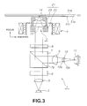
- Fig. 3 illustrates the composition of an optical pickup constituting the first example of this invention.
- Fig. 4 gives a frontal view of a two-lens system installed in the optical pickup constituting the first example of this invention.
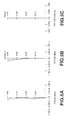
- Fig. 5 gives the optical characteristics of the two-lens system including spherical aberration, astigmatism and distortion.
- Fig. 6 gives the optical characteristic or coma in tangential and sagittal directions when the incident light beam has an angle of 0.000° or in the direction of optical axis.
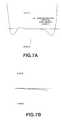
- Fig. 7 gives the optical characteristic or coma in tangential and sagittal directions when the incident light beam has an angle of 0.500°.
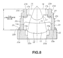
- Fig. 8 gives a sectional view of the lens tube incorporating the two-lens system.
- Fig. 9 gives a frontal view of the two-lens system where the second lens has an error of +10 ⁇ m in thickness.
- Fig. 10 gives the optical characteristics indicating wavefront aberrations when the two-lens system has the second lens with an error of +10 ⁇ m in thickness.
- Fig. 11 gives a frontal view of a two-lens system serving as a comparative example which has a second lens with an error of +10 ⁇ m in thickness.
- Fig. 12 gives the optical characteristics indicating wavefront aberrations of the comparative two-lens system which has the second lens with an error of +10 ⁇ m in thickness.
- Fig. 13 gives a frontal view of the two-lens system which has the second lens with an error of -10 ⁇ m in thickness.
- Fig. 14 gives the optical characteristics indicating wavefront aberrations of the two-lens system which has the second lens with an error of -10 ⁇ m in thickness.
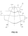
- Fig. 15 gives a frontal view of the comparative two-lens system which has the second lens with an error of -10 ⁇ m in thickness.
- Fig. 16 gives the optical charactenstics indicating wavefront aberrations of the comparative two-lens system which has the second lens with an error of -10 mm in thickness.
- Fig. 17 gives the optical characteristics indicating the relationship between errors in thickness of the second lens and RMS values of wavefront aberrations.
- Fig. 18 gives a frontal view of the two-lens system which has the first lens with an error of +10 ⁇ m in thickness.
- Fig. 19 gives the optical characteristics indicating wavefront aberrations when the two-lens system has the first lens with an error of +10 ⁇ m in thickness.
- Fig. 20 gives a frontal view of the comparative two-lens system which has the first lens with an error of +10 ⁇ m in thickness.
- Fig. 21 gives the optical characteristics indicating wavefront aberrations of the comparative two-lens system which has the first lens with an error of +10 ⁇ m in thickness.
- Fig. 22 gives the optical characteristics indicating the relationship between errors in thickness of the first lens and RMS values of wavefront aberrations.
- Fig. 23 gives a frontal view of the two-lens system in which each of the first and second lenses has an error of +10 ⁇ m in thickness.
- Fig. 24 gives the optical charactenstics indicating wavefront aberrations of the two-lens system which has the first and second lenses with an error of +10 ⁇ m each.
- Fig. 25 illustrates the composition of an optical pickup constituting the second example of this invention.
- Fig. 26 gives a frontal view of a two-lens system installed in the optical pickup constituting the second example of this invention.
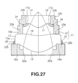
- Fig. 27 gives a sectional view of the lens tube incorporating the two-lens system.
- Fig. 28 gives a frontal view of the two-lens system incorporated in the optical pickup constituting the second example of this invention which has first and second lenses with an error of +10 ⁇ m in thickness each.
- Fig. 29 gives the optical characteristics indicating wavefront aberrations of two-lens system incorporated in the pickup constituting the second example of this invention, which has the first and second lenses with an error of +10 ⁇ m in thickness each.
- the first embodiment is an optical pickup which converges a laser beam from a semiconductor laser through a two-lens system including first and second lenses onto the signal recording surface of an optical disc.
- the two-lens system constitutes an objective lens.
- the two-lens system consists, as shown in Fig. 4, of a first lens 13 which has a first surface 15 upon which a laser beam from a semiconductor laser is incident and a second surface 16 which sends the laser beam transmitted from the first surface 15 towards a second lens 14, and a second lens 14 which has a third surface upon which the light flux sent from the second surface 16 is incident and a fourth surface 18 which directs the light flux transmitted from the third surface 17 onto an optical disc placed opposite thereto.
- the two-lens system 3 is so installed in an optical pickup as to allow the interval between the first and fourth surfaces 15 and 18 to correspond with a reference value.
- the optical disc has, as shown in Fig. 3, a transparent base plate 51a with a thickness of 0.1 mm on the surface to receive light.
- the optical disc 51 has a glass substrate 51b of 1.2 mm thick to support the transparent base plate 51a. Then, the optical disc 51 has a signal recording layer 51c inserted between the transparent base plate 51a and glass substrate 51b, and a light beam from a semiconductor laser 2 is converged by the two-lens system 3 onto that recording layer 51c.
- the optical pickup has, as shown in Fig. 3, a semiconductor laser 2 for emitting a laser beam and the two-lens system 3 whose optical axis is aligned with the semiconductor laser 2 for converging the laser beam onto the recording surface 51c of optical disc 51.
- the optical pickup 1 is further provided with a biaxial actuator 4 to support the two-lens system 3.
- the optical pickup 1 is still further provided with a collimator lens 5 arranged between the semiconductor laser 2 and the two-lens system 3 so as to have an optical axis matched, a diffraction grating 6, a polarized beam splitter 7 and a ⁇ /4 wavelength plate 8 when enumerated in order from the side of the semiconductor laser 2.
- a collimator lens 5 arranged between the semiconductor laser 2 and the two-lens system 3 so as to have an optical axis matched, a diffraction grating 6, a polarized beam splitter 7 and a ⁇ /4 wavelength plate 8 when enumerated in order from the side of the semiconductor laser 2.
- the optical pickup 1 is still further provided with a converging lens 9, a multi-lens 10 and a photodetector 11 at a place upon which a beam coming from an optical disc 51 and reflected from the reflective surface 7a of polanzed beam splitter 7 is incident.
- the semiconductor laser generates a laser beam with a wavelength of 635 nm. This laser beam is incident on the collimator lens 5.
- the collimator lens 5 turns the incident laser beam into a parallel light flux and directs it towards the diffraction grating 6.
- the diffraction grating 6 is a plate with parallel planes which has a diffraction grating inscribed on one of its main surfaces, and divides the incident light flux at least into three light fluxes including 0th order flux and ⁇ first order fluxes.
- the individual light fluxes produced by the diffraction grating 6 will serve as a main beam and sub-beams respectively when a three-beam method is put into practice, a method by which to detect signals suffering from tracking errors.
- the light fluxes produced as a result of splitting by the diffraction grating 6 is incident on the polarized beam splitter 7.
- the polarized beam splitter 7 has a reflective surface 7a which is so constructed as to transmit a light flux from the diffraction grating 6.
- the reflective surface 7a has, as will be described later, an optical characteristic to reflect a beam reflected from the optical disc 51.
- a light flux from the diffraction grating 6, without being reflected by the reflective surface 7a of polarized beam splitter 7, passes through it towards the ⁇ /4 wavelength plate 8.
- the ⁇ /4 wavelength plate 8 is a plate with approximately parallel planes, and allows a light flux from the polarized beam splitter 7 to pass through.
- the ⁇ /4 wavelength plate 8 has an optical characteristic to polarise by 90 degree beam reflected from the recording surface 51c of optical disc 51. A light beam passing through this ⁇ /4 wavelength plate 8 is incident on the two-lens system 3.
- the two-lens system 3 is composed of first and second lenses 13 and 14 having aspherical surfaces with a specified interval between them, as shown in Figs. 3 and 4.
- the first lens 13 has a first surface 15 upon which a light flux from the ⁇ /4 wavelength plate 8 is incident, and a second surface 16 which directs outward the light flux transmitted from the first surface 15.
- the first surface 15 is so constructed as to direct its aspherical convex surface towards the ⁇ /4 wavelength plate 8, and to have a flat surface 15a at periphery.
- the second surface 16 is so constructed as to direct its aspherical convex surface in the direction towards which light advances, and to have a flat surface 16a at periphery.
- the first lens 13 has two aspherical surfaces which are transformed into flat plates at periphery.
- the second lens 14 has a third surface 17 upon which a light flux from the second surface 16 of first lens 13 is incident, and a fourth surface 18 which directs the light flux transmitted from the third surface 17 towards an optical disc 51.
- the third surface 17 is so constructed as to direct its aspherical convex surface towards the first lens 13 placed opposite to it, and to have a flat surface 17a at periphery.
- the fourth surface 18 is, as described above, a surface opposite to an optical disc 51, and is made flat.
- the two-lens system 3 is so designed as to give a reference interval L 14 between the first surface 15 of first lens 13 and the fourth surface 18 of second lens 14, and to have the second lens 14 placed apart from the first lens 13.
- an optical lens having optical characteristics with a refractive index of 1.493009 and Abbe number of 86. l is made into the first lens 13.
- An optical lens having optical characteristics with a refractive index of 1.187007 and Abbe number of 61.3 is made into the second lens 14.
- a lens material called "FCD1" (trade name) provided by Hoya Co. can be made into the first lens 13
- a lens material called "BACD5" (trade name) provided by Hoya Co. can be made into the second lens 14.
- Table 1 also gives the data regarding radius of curvature (RDY) and thickness (THI) of the first, second, third and fourth surfaces.
- K in Table 1 represents a cone coefficient.
- A, B, C, D, E and F represent the fourth, sixth, eighth, tenth, twelfth and fourteenth order coefficients of non-sphericity respectively.
- first, second, third and fourth surfaces can be derived after above values have been put into the non-sphericity equation (1).
- X (Y 2 /R)/(1 + (1 - (1+K) (Y/R) 2 )) 1/2 + A ⁇ Y 4 + B ⁇ Y 6 + C ⁇ Y 8 + D ⁇ Y 10 + E ⁇ Y 12 + F ⁇ Y 14
- X represents a depth from the vertex of surface
- Y represents a height from optical axis
- R represents a radius of curvature of proximal axis.
- Table 1 further gives, with regard to the transparent substrate 51a, the data regarding radius of curvature and thickness of the surface (CG or cover glass) upon which light is incident, signal recording surface 51c and image surface (IMG). As shown in Table 2, the exit pupil diameter (EPD) and wavelength (WL) of laser beam are 4.500 mm and 635 nm, respectively.
- the object is at an infinitely distant position, and the rim of diaphragm 22a (STO) depicted in Fig. 4 is placed just in front of the first surface 15.
- the two-lens system 3 has an aperture number of 0.7 to 0.95.
- Aberrations inherent to the two-lens system 3 are as shown in Figs. 5-7.
- Figs 5A to 5C indicate the spherical aberration, astigmatism and distortion of two-lens system.
- the spherical aberration of two-lens system 3 is small and nearly constant regardless of height from the optical axis at which the measurement is performed as seen from Fig. 5A.
- the astigmatism or a difference in focal length between a tangential direction and a sagittal direction is small regardless of angle with which incident light impinges.
- coma which is experienced by an incident light beam with the height from optical axis of 1.00 and incident angle of 0.5 degree increases when the height is altered in a tangential direction.
- Coma which is experienced by an incident light beam with the height from optical axis of 1.00 and incident angle of 0.5 degree is only slight even when the height is altered in a sagittal direction as shown in Fig. 7B.
- the two-lens system 3 has the second lens 14 placed apart from the first lens 13 such that the interval between the first and the fourth surfaces 15 and 18 may take a constant length of L 14 .
- the two-lens system can be said to contain, so to say, another refractive lens (third lens) made of air between the first and the second lenses 13 and 14.
- the third lens is forcibly altered of its thickness by the same absolute value of that error.
- first lens 13 or second lens 14 causes the responsible lens to produce an aberration. It also causes the third lens to produce an aberration of opposite polarity to that caused by the first or second lens as the case may be.
- the two-lens system 3 is composed of the first and the second lenses 13 and 14 placed in a lens tube 21.
- the lens tube 21 is composed of a lens supporting section 22 to support the first lens 13 and a lens storing section 14 cylindrical in shape to store the second lens 14.
- the lens tube 21 has first and second mounting reference surfaces 23a and 23b in the lens storing section 23.
- the first and the second mounting reference surfaces 23a and 23b are designed such that their interval corresponds with a reference value, and will serve as references when positioning of the first and the second lenses 13 and 14 is carried out.
- the lens supporting section 22 of lens tube 21 has a cylindrical shape.
- the lens supporting section 22 has a diaphragm 22a to adjust the intensity of incoming light flux and a supporting surface 22b to support the first surface 15 of the first lens 13 at its one end.
- the first lens 13 is stabilized by attaching the periphery 15a of first surface 15 to the supporting surface 22b. Namely, the lens supporting section adjusts the flux of light incident on the first lens supported by the lens supporting surface 22b with the diaphragm 22a.
- the lens storing section 23 of lens tube 21 has, on one end, a first mounting reference surface 23a which joins with the lens supporting surface 22b of lens supporting section 22, and has, on the other end, a second mounting reference surface 23b.
- the lens storing section 23 has, on one end, a first storing segment 23c which is so prepared as to surround the periphery 13a of first lens 13, and has, on the other end, a second storing segment 23d which is so prepared as to accommodate the second lens 14.
- the second lens 14 is stored in the second storing segment 23a in such a way as to make the fourth surface 18 flush with the second mounting reference surface 23b.
- the second lens 14 is fixed to the inner surface of second storing segment 23d through an adhesive 24.
- the lens storing section 23a has the first mounting reference surface 23a jointed with the supporting surface 22b of lens supporting section 22.
- the lens storing segment 23 is jointed with the lens supporting section 22 through an adhesive 25.
- the first surface 15 becomes flush with the supporting surface 22b of lens supporting section 22, and the fourth surface 18 becomes flush with the second reference surface 23b of lens storing section 23, thereby putting the interval L 14 between the first and the fourth surfaces 15 and 17 in agreement with a reference value.
- the two-lens system 3 is supported, as shown in Fig. 3, with a biaxial actuator 4 by way of the lens tube 21.
- the biaxial actuator 4 adjusts the movement of two-lens system 3 in focusing and tracking directions, based on focusing and tracking error signals.
- the two-lens system 3 supported by the biaxial actuator 4 converges a light beam on the signal recording surface 51c of an optical disc 51.
- the converged beam is reflected from the signal recording surface 51c, to become a reflected beam incident on the fourth surface 18 of two-lens system 3.
- the two-lens system 3 transmits the reflected beam, and directs it towards the ⁇ /4 wavelength plate 8.
- the ⁇ /4 wavelength plate 8 polarises the incident beam by 90° and directs it towards a polarized beam splitter 7.
- the polarized beam splitter 7 reflects the reflected beam which has undergone polarisation through passage of the ⁇ /4 wavelength plate 8 at the reflective surface 7a.
- the light flux reflected from the reflective surface 7a is directed towards a converging lens 9.
- the converging lens 9 converges the reflected beam reflected from the reflective surface 7a of polarized beam splitter 7, and directs it towards a multi-lens 10.
- the multi-lens 10 is composed of a cylindrical lens 10a and a concave lens combined into unity. This multi-lens 10, while causing the incoming reflected beam to produce an astigmatism, converges it onto a light detector 11.
- the light detector 11 has a light sensitive surface composed of six plates. This light sensitive detector 11 receives the light flux converged by the multi-lens 10, and generates an electric signal in accordance with the intensity of that light flux.
- the optical pickup 1 based on the electric signal from the light detector 11, detects a focusing error signal by means of a focusing error detection circuit working on astigmatism detection, and a tracking error signal by means of a tracking error detection circuit working on a three-beam principle. Then, the optical pickup 1, based on the focusing error and tracking error signals, makes a servo-treatment which consists of adjusting the position of two-lens system 3 by properly activating the biaxial actuator 4. In addition, the optical pickup 1 writes and reads information signals onto and from the signal recording surface 51c of optical disc 51.
- the optical pickup 1 as long as it is provided with a two-lens system 3 where the interval L 14 between first and fourth lenses 15 and 18 corresponds with a reference value, can be free from any aberrations caused by errors in thickness of lenses constituting the two-lens system.
- the optical pickup I can write and read less degraded information signals onto and from the signal recording surface 51c of optical disc 51, even if there are errors in thickness of the lenses constituting the two-lens system 3.
- the resulting wavefront aberrations and their RMS values are as shown in Fig. 10.
- the magnitude of wavefront aberrations is expressed relative to that of one wavelength.
- the RMS value of wavefront aberrations was 0.017 rms, or a sufficiently tolerable value.
- the comparative example consisted of, as shown in Fig. 11, a two-lens system 61 which had been constructed such that the interval L 23 between the second and third surfaces 65 and 66 became constant.
- the interval between the first and the fourth surfaces 64 and 67 of this comparative example was longer by 10 ⁇ m than the corresponding interval of the two-lens system of this invention or L 14 shown in Fig. 9.
- the wavefront aberrations obtained from the two-lens system 61 of comparative example are as shown in Fig. 12, and larger than the corresponding results of this invention shown in Fig. 10.
- the RMS value obtained from the comparative example was 0.064 rms or close to the upper tolerable limit.
- the resulting wavefront aberrations and their RMS values are as shown in Fig. 14.
- the RMS value of wavefront aberrations was 0.021 rms, or a sufficiently tolerable value.
- the comparative example consisted of, as shown in Fig. 15, a two-lens system 61 which had been constructed such that the interval L 23 between the second and the third surfaces 65 and 66 became constant.
- the interval between the first and the fourth surfaces 64 and 67 of this comparative example was shorter by 10 mm than the corresponding interval of two-lens system of this invention or L 14 shown in Fig. 13.
- the wavefront aberrations obtained from the two-lens system 61 of comparative example are as shown in Fig. 16, and larger than the corresponding results of this invention shown in Fig. 14.
- the RMS value of wavefront aberrations obtained from the comparative example was 0.064 rms or close to the upper tolerable limit.
- Fig. 17 gives RMS values of wavefront aberrations as a function of errors in thickness of the second lens of the two-lens system.
- Solid circles ( ⁇ ) plot the results obtained from the two-lens system 3 where the interval L14 of the first and the fourth surfaces 15 and 18 corresponds with a reference value, or the two-lens system of this invention, while open circles (O) plot the results obtained from the two-lens system 61 where the interval L 23 between the second and third surfaces 65 and 66 is constant, or the two-lens system of the comparative example.
- the resulting RMS values of wavefront aberrations are obviously smaller for the two-lens system 3 where the interval L 14 between the first and the fourth surfaces 15 and 18 corresponds with a reference value, or the two-lens system of this invention than for the comparative two-lens system.
- the resulting wavefront aberrations and their RMS values are as shown in Fig. 19.
- the RMS value of wavefront aberrations was 0.017 rms, or a sufficiently tolerable value.
- the comparative example consisted of, as shown in Fig. 20, a two-lens system 61 which had been constructed such that the interval L 23 between the second and the third surfaces 65 and 66 became constant.
- the interval between the first and the fourth surfaces 64 and 67 of this comparative example was longer by 10 ⁇ m than the corresponding interval of two-lens system of this invention or L 14 shown in Fig. 18.
- the wavefront aberrations obtained from the two-lens system 61 of comparative example are as shown in Fig. 21, and larger than the corresponding results of this invention shown in Fig. 19.
- the RMS value obtained from the comparative example was 0.023 rms.
- Fig. 22 gives RMS values of wavefront aberrations as a function of errors in thickness of the first lens of the two-lens system.
- Solid circles ( ⁇ ) plot the results obtained from the two-lens system 3 where the interval L 14 of the first and the fourth surfaces 15 and 18 corresponds with a reference value, or the two-lens system of this invention, while open circles (O) plot the results obtained from the two-lens system 61 where the interval L 23 between the second and the third surfaces 65 and 66 is constant, or the two-lens system of the comparative example.
- the resulting RMS values of wavefront aberrations are smaller for the two-lens system 3 where the interval L 14 between the first and the fourth surfaces 15 and 18 corresponds with a reference value, or the two-lens system of this invention than for the comparative two-lens system.
- each of the first and the second lenses 13 and 14 it is possible for each of the first and the second lenses 13 and 14 to have an error of +10 ⁇ m in thickness as shown in Fig. 23.
- the resulting two-lens system will give practically no wavefront aberrations as seen from Fig. 24
- the RMS value of wavefront aberrations will be 0.013 rms as shown in Fig. 24, or a sufficiently tolerable value.
- the second embodiment like the first one, is an optical pickup which converges a laser beam from a semiconductor laser through a two-lens system consisting of first and second lenses onto the signal recording surface of an optical disc.
- the two-lens system consists, as shown in Fig. 26, of: a first lens 13 having a first surface 15 upon which a laser beam from a semiconductor laser is incident and a second surface 16 which sends the laser beam transmitted from the first surface 15 towards a second lens 14; and a second lens 14 having a third surface upon which the light flux sent from the second surface 16 is incident and a fourth surface 18 which directs the light flux transmitted from the third surface 17 onto an optical disc placed opposite thereto.
- the two-lens system 30 is so installed in an optical pickup 29 as to allow the interval L 24 between the second and the fourth surfaces 16 and 18 to correspond with a reference value.
- optical pickup 29 representing the second embodiment
- the same elements with those constituting the optical pickup 1 of the first embodiment will be represented by the same numerals, and their explanation will be omitted.
- the optical pickup 29 has, as shown in Fig. 25, a semiconductor laser 2 for emitting a laser beam and the two-lens system 30 which is aligned with the optical axis of the semiconductor laser 2 to converges the laser beam onto the recording surface 51c of optical disc 51.
- the optical pickup 29 is further provided with a biaxial actuator 4 to support the two-lens system 30.
- the optical pickup 29 still further has a collimator lens 5 inserted between the semiconductor laser 2 and two-lens system 30 with its optical axis aligned, a diffraction grating 6, a polarized beam splitter 7 and a ⁇ /4 wavelength plate 8 when enumerated in order from the side of the semiconductor laser 2.
- the optical pickup 29 is still further provided with a converging lens 9, a multi-lens 10 and a photodetector 11 at a place upon which a beam reflected from an optical disc 51 and further reflected from the reflective surface 7a of polarized beam splitter 7 is incident.
- the first and the second lenses 13 and 14 are constructed in the same way as with the corresponding lenses of the first embodiment described earlier.
- the two-lens system 30 is designed to place the second lens 14 apart from the first lens 13 so much as to give a reference value interval L 24 between the second and the fourth surfaces 16 and 18.
- the two-lens system 30 can be said to contain, so to say, another refractive lens (third lens) made of air between the first and the second lenses 13 and 14.
- the second lens 14 has a larger aperture number against incoming light flux than does the first lens 13, transformations due to wall thickness are less with the second lens 14 than with the first lens 13. Accordingly, if errors in thickness of the second lens 14 can be corrected properly, aberrations of the lens system in question can be limited within a sufficiently tolerable level.
- the second lens 14 has an error in thickness which causes it to develop an aberration. However, it also causes the third lens to produce an aberration of opposite polarity to that caused by the second lens, to cancel out the latter.
- the two-lens system 30 is composed of the first and the second lenses 13 and 14 placed in a lens tube 31.
- the lens tube 31 is composed of lens supporting section 32 to support the first lens 13 and a lens storing section 33 to store the second lens 14.
- the lens tube 21 has first and second mounting reference surfaces 33a and 33b in the lens storing section 33.
- the first and second mounting reference surfaces 33a and 33b are designed such that their interval corresponds with a reference value, and will serve as references when positioning of the first and the second lenses 13 and 14 is carried out.
- the lens supporting section 32 of lens tube 31 has a cylindrical shape.
- the lens supporting section 32 has a diaphragm 32a to adjust the intensity of incoming light flux and a supporting surface 32b to support the first lens 13 at its one end.
- the first lens 13 is stabilized by attaching the periphery 15a of first surface 15 to the supporting surface 32b. Namely, the lens supporting section adjusts the flux of light incident on the first lens 13 supported by the lens supporting surface 32b using the diaphragm 32a.
- the lens storing section 33 of lens tube 31 has an internal diameter slightly larger than the extenial diameter of first lens 13, and has an approximately cylindrical shape.
- the lens storing section 33 has, on one end, a first mounting reference surface 33a which joins with the first lens 13, and has, on the other end, a second mounting reference surface 33b.
- the lens storing section 33 has, in addition, a lens holder 32c which has an internal diameter nearly the same with the external diameter of second lens 14.
- the second lens 14 is stored in the second storing segment 33c in such a way as to make the fourth surface 18 flush with the second mounting reference surface 33b.
- the second lens 14 is fixed to the lens storing section 33 through an adhesive 34.
- the lens storing section 33 has the first mounting reference surface 33a jointed with the periphery 16a of second surface 16 of first lens 13.
- the first lens 13 is jointed with the lens supporting section 32b through an adhesive 35.
- the fourth surface 18 becomes flush with the second mounting reference surface 33b, and the first reference surface 33a of lens storing section 33 comes into contact with the second surface 16.
- This arrangement ensures the interval L 24 between the second and the fourth surfaces 16 and 18 to correspond with a reference value.
- the optical pickup 29, as long as it is provided with a two-lens system 3 where the interval L 24 between second and fourth lenses 16 and 18 corresponds with a reference value, can reduce wavefront aberrations. In other words, as long as above requirement is met, the optical pickup 29 can write and read less degraded information signals onto and from the signal recording surface of an optical disc, even if there are errors in thickness of the lenses constituting the two-lens system 30.
- the first and the second lenses 13 and 14 were allowed to have an en-or of +10 ⁇ m in thickness each, and the resulting wavefront aberrations are shown in Fig. 29.
- the experimental condition was as represented by Fig. 28: the first and the second lenses had an error of +10 ⁇ m in thickness each. In this case, however, as the interval. L 24 between second and fourth surfaces 16 and 18 corresponded with a reference value, the resulting two-lens system gave wavefront aberrations as seen from Fig. 29
- the RMS value of wavefront aberrations was 0.048 nns or a sufficiently tolerable value.
- the first lens of two-lens system was exclusively exposed to incident light with parallel fluxes, but the above description can be applied to the two-lens system whose first lens is exposed to light emanating from a source at a finite distance.
- the optical pickup of this invention being provided with the lens tube wherein reference surfaces for mounting of first and fourth lens surfaces of the two-lens system are provided to allow those lens surfaces to be positioned with an interval of a reference value between them, can limit aberrations within a tolerable range without resorting to a special device even if errors are produced in the lens thickness of two-lens system.
- the optical pickup of this invention being provided with the lens tube wherein reference surfaces for mounting of second and fourth lens surfaces of the two-lens system are provided to allow those lens surfaces to be positioned with an interval of a reference value between them, can limit aberrations within a tolerable range without resorting to a special device even if errors are produced in the lens thickness of two-lens system.
- the method of this invention for assembling objective lenses of an optical pickup consists of assembling the two-lens system such that the second and fourth surfaces may have an interval of a reference value, thereby limiting aberrations within a tolerable range without resorting to a special device even if errors are produced in the lens thickness of two-lens system.
- the method of this invention for assembling objective lenses of an optical pickup consists of assembling the two-lens system such that the second and fourth surfaces have an interval of a reference value, thereby limiting aberrations within a tolerable range without resorting to a special device even if errors are produced in the lens thickness of two-lens system.
Abstract
Description
| RDY (radius of curvature) | THI (thickness) | GLA (name of glass) | |
| OBJ | Infinite distance | Infinite distance | |
| STO | Infinite distance | 0.0 | |
| First surface | 2.43644 | 2.297518 | First lens |
| K:-0.530603 A:0.462792E-03 B:-0.131930E-03 C:-0.216921E-04 D:-0.526207E-06 E:0.0 F:0.0 | |||
| Second surface | 19.29810 | 1.042695 | |
| K:-26.403411 A:-0.838023E-03 B:0.455037E-03 C:0.502887E-04 D:0.0 E:0.0 F:0.0 | |||
| Third surface | 1.50881 | 1.500 | Second lens |
| K:-0.198463 A:-0.999579E-03 B:-0.127468E-03 C:0.579594E-04 D:-0.317005E-02 E:0.0 F:0.0 | |||
| Fourth surface | Infinite | 0.3 | |
| distance | |||
| K:0.0 A:0.0 B:0.0 C:0.0 D:0.0 E:0.0 F:0.0 | |||
| Surface upon which light is incident | Infinite distance | 0.1 | CG |
| Signal bearing surface | Infinite distance | 0.0 | |
| IMG | Infinite distance | 0.0 |
| EPD (exit pupil diameter (mm)) | 4.500 |
| WL (wavelength (nm)) | 635 |
| Name of glass | Refractive index /Abbe number |
| First lens | 1.493009/86.1 |
| Second lens | 1.587007/61.3 |
| CG (cover glass) | 1.533 |
Claims (8)
- An optical pickup comprising a two-lens system having at least one aspheric surface, wherein a lens tube is provided in such a manner that a reference value is a design length between a mounting reference surface of a first surface (15) of said two-lens system and a mounting reference surface of a fourth surface (18) of said two-lens system.
- An optical pickup comprising a two-lens system having at least one aspheric surface, wherein a lens tube is provided in such a manner that a reference value is a design length between a mounting reference surface of a second surface (16) of said two-lens system and a mounting reference surface of a fourth surface (18) of said two-lens system.
- An optical pickup as claimed in claim 1 or claim 2, wherein said fourth surface (18) is arranged to face an optical recording medium.
- An optical pickup objective lens assembling method for assembling a two-lens system having at least one aspheric surface for an optical pickup, wherein said two-lens system is assembled so that a distance between a first surface (15) and a fourth surface (18) is a reference value.
- An optical pickup objective lens assembling method as claimed in claim 4, wherein a lens tube is provided so as to have a mounting reference surface with an identical distance as said reference value, and said first surface (15) and said fourth surface (18) are mounted on the same surface as said mounting reference surface.
- An optical pickup objective lens assembling method for assembling a two-lens system having at least one aspheric surface for an optical pickup, wherein said two-lens system is assembled so that a distance between a second surface (16) and a fourth surface (18) is a reference value.
- An optical pickup objective lens assembling method as claimed in claim 6, wherein a lens tube is provided so as to have a mounting reference surface with an identical distance as said reference value, and said second surface (16) and said fourth surface (18) are mounted on the same surface as said mounting reference surface.
- An optical pickup objective lens assembling method as claimed in claim 6, wherein said fourth surface (18) is arranged so as to face an optical recording medium.
Applications Claiming Priority (2)
| Application Number | Priority Date | Filing Date | Title |
|---|---|---|---|
| JP05216097A JP3608333B2 (en) | 1997-03-06 | 1997-03-06 | Optical pickup and method of assembling objective lens for optical pickup |
| JP52160/97 | 1997-03-06 |
Publications (3)
| Publication Number | Publication Date |
|---|---|
| EP0863502A2 true EP0863502A2 (en) | 1998-09-09 |
| EP0863502A3 EP0863502A3 (en) | 1998-12-16 |
| EP0863502B1 EP0863502B1 (en) | 2006-08-30 |
Family
ID=12907099
Family Applications (1)
| Application Number | Title | Priority Date | Filing Date |
|---|---|---|---|
| EP98400536A Expired - Lifetime EP0863502B1 (en) | 1997-03-06 | 1998-03-06 | An optical pickup and an optical pickup objective lens assembling method |
Country Status (7)
| Country | Link |
|---|---|
| US (1) | US6055113A (en) |
| EP (1) | EP0863502B1 (en) |
| JP (1) | JP3608333B2 (en) |
| KR (1) | KR100486134B1 (en) |
| CN (1) | CN1126084C (en) |
| DE (1) | DE69835712T2 (en) |
| ID (1) | ID20342A (en) |
Cited By (9)
| Publication number | Priority date | Publication date | Assignee | Title |
|---|---|---|---|---|
| US6487026B2 (en) | 2000-03-27 | 2002-11-26 | Koninklijke Philips Electronics N.V. | Optical lens system comprising two more than half-spherical lenses |
| US6510011B2 (en) | 2000-03-27 | 2003-01-21 | Koninklijke Philips Electronics N.V. | Optical scanning device |
| WO2003094159A1 (en) * | 2002-05-02 | 2003-11-13 | Dataplay, Inc. | Method of assembling optical components for an optical pick up |
| US6665132B2 (en) | 2001-04-25 | 2003-12-16 | Koninklijke Philips Electronics N.V. | Optical lens system comprising at least one lens of a synthetic material |
| EP1376186A1 (en) * | 2002-06-25 | 2004-01-02 | Konica Corporation | Objective lens for optical pickup apparatus and recording/reproducing apparatus |
| EP1406105A1 (en) * | 2001-07-09 | 2004-04-07 | Sony Corporation | Objective lens, and optical pickup device using the objective lens |
| US6829210B2 (en) * | 2000-09-14 | 2004-12-07 | Sony Corporation | Optical head and optical pickup |
| US6873580B2 (en) | 2001-05-01 | 2005-03-29 | Dphi Acquisitions, Inc. | Objective lens alignment in optical pickup unit assembly |
| NL1015455C2 (en) * | 1999-06-22 | 2007-03-27 | Sharp Kk | Optical recording device and optical recording medium. |
Families Citing this family (8)
| Publication number | Priority date | Publication date | Assignee | Title |
|---|---|---|---|---|
| US6392819B1 (en) * | 1999-05-11 | 2002-05-21 | Sharp Kabushiki Kaisha | Objective lens and fabrication method thereof |
| JP3809047B2 (en) * | 2000-05-10 | 2006-08-16 | シャープ株式会社 | Objective lens barrel driving apparatus and optical information recording / reproducing apparatus |
| KR100442905B1 (en) * | 2000-10-17 | 2004-08-02 | 마쯔시다덴기산교 가부시키가이샤 | An objective lens assembly, an apparatus for assembling/adjusting an objective lens assembly, an optical head, and an optical recording/reproduction apparatus |
| US6567223B2 (en) * | 2001-06-01 | 2003-05-20 | Eastman Kodak Company | Molded lens element having a two-dimensional reference molded therein |
| JP2006085837A (en) * | 2004-09-16 | 2006-03-30 | Konica Minolta Opto Inc | Objective lens unit and optical pickup device using the same |
| WO2012108052A1 (en) * | 2011-02-10 | 2012-08-16 | 信越ポリマー株式会社 | Monocrystalline substrate production method and monocrystalline member with modified layer formed therein |
| IL267976B (en) * | 2017-01-25 | 2022-08-01 | Nexa3D Inc | Method and apparatus using light engines for photo-curing of liquid polymers to form three-dimensional objects |
| EP3794392A4 (en) | 2018-05-14 | 2021-05-19 | Sharp Kabushiki Kaisha | Two-lens optical system, beam combining module, projector, and method for assembling two-lens optical system |
Citations (2)
| Publication number | Priority date | Publication date | Assignee | Title |
|---|---|---|---|---|
| US4953959A (en) * | 1988-05-12 | 1990-09-04 | Olympus Optical Co., Ltd. | Objective lens for optical disks |
| US5467225A (en) * | 1991-10-11 | 1995-11-14 | Nikon Corporation | Objective lens for an optical disk drive |
Family Cites Families (2)
| Publication number | Priority date | Publication date | Assignee | Title |
|---|---|---|---|---|
| US2161368A (en) * | 1937-07-16 | 1939-06-06 | Eastman Kodak Co | Lens mount |
| DE3405789C2 (en) * | 1983-02-19 | 1986-01-02 | Olympus Optical Co., Ltd., Tokio/Tokyo | Lens member |
-
1997
- 1997-03-06 JP JP05216097A patent/JP3608333B2/en not_active Expired - Fee Related
-
1998
- 1998-03-03 KR KR10-1998-0006884A patent/KR100486134B1/en not_active IP Right Cessation
- 1998-03-05 ID IDP980328A patent/ID20342A/en unknown
- 1998-03-05 US US09/035,138 patent/US6055113A/en not_active Expired - Fee Related
- 1998-03-06 DE DE69835712T patent/DE69835712T2/en not_active Expired - Fee Related
- 1998-03-06 CN CN98106641A patent/CN1126084C/en not_active Expired - Fee Related
- 1998-03-06 EP EP98400536A patent/EP0863502B1/en not_active Expired - Lifetime
Patent Citations (2)
| Publication number | Priority date | Publication date | Assignee | Title |
|---|---|---|---|---|
| US4953959A (en) * | 1988-05-12 | 1990-09-04 | Olympus Optical Co., Ltd. | Objective lens for optical disks |
| US5467225A (en) * | 1991-10-11 | 1995-11-14 | Nikon Corporation | Objective lens for an optical disk drive |
Cited By (12)
| Publication number | Priority date | Publication date | Assignee | Title |
|---|---|---|---|---|
| NL1015455C2 (en) * | 1999-06-22 | 2007-03-27 | Sharp Kk | Optical recording device and optical recording medium. |
| US6487026B2 (en) | 2000-03-27 | 2002-11-26 | Koninklijke Philips Electronics N.V. | Optical lens system comprising two more than half-spherical lenses |
| US6510011B2 (en) | 2000-03-27 | 2003-01-21 | Koninklijke Philips Electronics N.V. | Optical scanning device |
| US6829210B2 (en) * | 2000-09-14 | 2004-12-07 | Sony Corporation | Optical head and optical pickup |
| US6665132B2 (en) | 2001-04-25 | 2003-12-16 | Koninklijke Philips Electronics N.V. | Optical lens system comprising at least one lens of a synthetic material |
| US6873580B2 (en) | 2001-05-01 | 2005-03-29 | Dphi Acquisitions, Inc. | Objective lens alignment in optical pickup unit assembly |
| EP1406105A1 (en) * | 2001-07-09 | 2004-04-07 | Sony Corporation | Objective lens, and optical pickup device using the objective lens |
| US7170693B2 (en) | 2001-07-09 | 2007-01-30 | Sony Corporation | Objective lens, and optical pickup device using the objective lens |
| EP1406105A4 (en) * | 2001-07-09 | 2007-05-30 | Sony Corp | Objective lens, and optical pickup device using the objective lens |
| WO2003094159A1 (en) * | 2002-05-02 | 2003-11-13 | Dataplay, Inc. | Method of assembling optical components for an optical pick up |
| EP1376186A1 (en) * | 2002-06-25 | 2004-01-02 | Konica Corporation | Objective lens for optical pickup apparatus and recording/reproducing apparatus |
| US7079473B2 (en) | 2002-06-25 | 2006-07-18 | Konica Corporation | Objective lens, optical pickup apparatus and recording reproducing apparatus |
Also Published As
| Publication number | Publication date |
|---|---|
| JPH10255303A (en) | 1998-09-25 |
| EP0863502A3 (en) | 1998-12-16 |
| DE69835712T2 (en) | 2007-09-06 |
| JP3608333B2 (en) | 2005-01-12 |
| KR100486134B1 (en) | 2005-09-02 |
| CN1203414A (en) | 1998-12-30 |
| KR19980079820A (en) | 1998-11-25 |
| ID20342A (en) | 1998-12-03 |
| CN1126084C (en) | 2003-10-29 |
| DE69835712D1 (en) | 2006-10-12 |
| US6055113A (en) | 2000-04-25 |
| EP0863502B1 (en) | 2006-08-30 |
Similar Documents
| Publication | Publication Date | Title |
|---|---|---|
| US6055113A (en) | Optical pickup and an optical pickup objective lense assembling method | |
| KR100388515B1 (en) | Optical pickup apparatus | |
| EP1986189B1 (en) | Optical pickup apparatus | |
| KR100653289B1 (en) | Optical head and recording/reproducing device | |
| CA2345788C (en) | Objective lens inclinable to correct for a third-order coma aberration and an optical head device including the same | |
| JPWO2002027715A1 (en) | Optical system for optical disk, optical head device for optical disk, and optical drive device | |
| KR100765741B1 (en) | Objective lens having single lens and optical pickup apparatus employing it | |
| EP1271495A2 (en) | Objective lens, optical pickup apparatus, and recording and/or reproducing apparatus | |
| US20040257667A1 (en) | Objective optical system employing grin lens | |
| US5818809A (en) | Optical system for recording and/or reproducing an optical information recording medium | |
| EP1329881A2 (en) | Light converging optical system, optical pickup apparatus, aberration correcting element and objective lens | |
| KR100560573B1 (en) | Catadioptric lens, optical head, and optical recording/reproducing apparatus | |
| US20050232121A1 (en) | Refracting objective optical system and optical recording/reproducing device using the same | |
| CN100446097C (en) | Objective lens and scanning device using such an objective lens | |
| JPH05303766A (en) | Optical element for optical disk and optical head using the same | |
| US6151174A (en) | Device for optically scanning a record carrier | |
| US6898024B2 (en) | Optical system for optical pickup employing coma compensating element | |
| US6741539B2 (en) | Optical system for optical head | |
| JP3462997B2 (en) | Method of adjusting objective lens for optical pickup, objective lens for optical pickup, objective lens barrel, and method of adjusting the same | |
| US5015078A (en) | Aspherical single lens | |
| KR100535341B1 (en) | Optical pickup apparatus | |
| US20050047310A1 (en) | Spherical aberration corrector plate comprising two wedge-shaped plates enabled to relatively shift | |
| EP1376186B1 (en) | Objective lens for optical pickup apparatus and recording/reproducing apparatus | |
| KR100562338B1 (en) | Optical pickup apparatus | |
| JPH05342619A (en) | Optical pickup device |
Legal Events
| Date | Code | Title | Description |
|---|---|---|---|
| PUAI | Public reference made under article 153(3) epc to a published international application that has entered the european phase |
Free format text: ORIGINAL CODE: 0009012 |
|
| AK | Designated contracting states |
Kind code of ref document: A2 Designated state(s): AT BE CH DE DK ES FI FR GB GR IE IT LI LU MC NL PT SE |
|
| AX | Request for extension of the european patent |
Free format text: AL;LT;LV;MK;RO;SI |
|
| PUAL | Search report despatched |
Free format text: ORIGINAL CODE: 0009013 |
|
| AK | Designated contracting states |
Kind code of ref document: A3 Designated state(s): AT BE CH DE DK ES FI FR GB GR IE IT LI LU MC NL PT SE |
|
| AX | Request for extension of the european patent |
Free format text: AL;LT;LV;MK;RO;SI |
|
| 17P | Request for examination filed |
Effective date: 19990616 |
|
| AKX | Designation fees paid |
Free format text: DE FR GB |
|
| 17Q | First examination report despatched |
Effective date: 19991020 |
|
| GRAP | Despatch of communication of intention to grant a patent |
Free format text: ORIGINAL CODE: EPIDOSNIGR1 |
|
| GRAS | Grant fee paid |
Free format text: ORIGINAL CODE: EPIDOSNIGR3 |
|
| GRAA | (expected) grant |
Free format text: ORIGINAL CODE: 0009210 |
|
| AK | Designated contracting states |
Kind code of ref document: B1 Designated state(s): DE FR GB |
|
| REG | Reference to a national code |
Ref country code: GB Ref legal event code: FG4D |
|
| REF | Corresponds to: |
Ref document number: 69835712 Country of ref document: DE Date of ref document: 20061012 Kind code of ref document: P |
|
| ET | Fr: translation filed | ||
| PLBE | No opposition filed within time limit |
Free format text: ORIGINAL CODE: 0009261 |
|
| STAA | Information on the status of an ep patent application or granted ep patent |
Free format text: STATUS: NO OPPOSITION FILED WITHIN TIME LIMIT |
|
| 26N | No opposition filed |
Effective date: 20070531 |
|
| PGFP | Annual fee paid to national office [announced via postgrant information from national office to epo] |
Ref country code: GB Payment date: 20090304 Year of fee payment: 12 |
|
| PGFP | Annual fee paid to national office [announced via postgrant information from national office to epo] |
Ref country code: DE Payment date: 20090226 Year of fee payment: 12 |
|
| PGFP | Annual fee paid to national office [announced via postgrant information from national office to epo] |
Ref country code: FR Payment date: 20090316 Year of fee payment: 12 |
|
| GBPC | Gb: european patent ceased through non-payment of renewal fee |
Effective date: 20100306 |
|
| REG | Reference to a national code |
Ref country code: FR Ref legal event code: ST Effective date: 20101130 |
|
| PG25 | Lapsed in a contracting state [announced via postgrant information from national office to epo] |
Ref country code: FR Free format text: LAPSE BECAUSE OF NON-PAYMENT OF DUE FEES Effective date: 20100331 |
|
| PG25 | Lapsed in a contracting state [announced via postgrant information from national office to epo] |
Ref country code: DE Free format text: LAPSE BECAUSE OF NON-PAYMENT OF DUE FEES Effective date: 20101001 |
|
| PG25 | Lapsed in a contracting state [announced via postgrant information from national office to epo] |
Ref country code: GB Free format text: LAPSE BECAUSE OF NON-PAYMENT OF DUE FEES Effective date: 20100306 |