EP0862688B1 - Controlled temperature rocket nozzle - Google Patents
Controlled temperature rocket nozzle Download PDFInfo
- Publication number
- EP0862688B1 EP0862688B1 EP96937608A EP96937608A EP0862688B1 EP 0862688 B1 EP0862688 B1 EP 0862688B1 EP 96937608 A EP96937608 A EP 96937608A EP 96937608 A EP96937608 A EP 96937608A EP 0862688 B1 EP0862688 B1 EP 0862688B1
- Authority
- EP
- European Patent Office
- Prior art keywords
- nozzle
- wall
- inflection point
- location
- bell
- Prior art date
- Legal status (The legal status is an assumption and is not a legal conclusion. Google has not performed a legal analysis and makes no representation as to the accuracy of the status listed.)
- Expired - Lifetime
Links
- 238000001816 cooling Methods 0.000 claims description 8
- 230000009977 dual effect Effects 0.000 claims description 8
- 239000000463 material Substances 0.000 description 6
- 238000000576 coating method Methods 0.000 description 3
- 230000000694 effects Effects 0.000 description 3
- 230000001133 acceleration Effects 0.000 description 2
- 230000004323 axial length Effects 0.000 description 1
- 239000011153 ceramic matrix composite Substances 0.000 description 1
- 239000011248 coating agent Substances 0.000 description 1
- 230000001419 dependent effect Effects 0.000 description 1
- 238000005516 engineering process Methods 0.000 description 1
- 239000007769 metal material Substances 0.000 description 1
- 238000000034 method Methods 0.000 description 1
- 238000010079 rubber tapping Methods 0.000 description 1
- 238000000926 separation method Methods 0.000 description 1
Images

Classifications
-
- F—MECHANICAL ENGINEERING; LIGHTING; HEATING; WEAPONS; BLASTING
- F02—COMBUSTION ENGINES; HOT-GAS OR COMBUSTION-PRODUCT ENGINE PLANTS
- F02K—JET-PROPULSION PLANTS
- F02K9/00—Rocket-engine plants, i.e. plants carrying both fuel and oxidant therefor; Control thereof
- F02K9/97—Rocket nozzles
-
- F—MECHANICAL ENGINEERING; LIGHTING; HEATING; WEAPONS; BLASTING
- F05—INDEXING SCHEMES RELATING TO ENGINES OR PUMPS IN VARIOUS SUBCLASSES OF CLASSES F01-F04
- F05D—INDEXING SCHEME FOR ASPECTS RELATING TO NON-POSITIVE-DISPLACEMENT MACHINES OR ENGINES, GAS-TURBINES OR JET-PROPULSION PLANTS
- F05D2250/00—Geometry
- F05D2250/70—Shape
- F05D2250/71—Shape curved
- F05D2250/713—Shape curved inflexed
Definitions
- the invention refers to a rocket nozzle having axially double bell shape, i.e. of so-called “Dual Bell” type, and having an outwardly directed change of curvature of the contour line or generatrix at the inflection point between the two bell shapes.
- the Dual Bell shape of rocket nozzles is known from (cf. US 3394 549 A) the early 60's for providing an altitude compensation.
- sea level operation mode such a Dual Bell nozzle the inflection point will force the flow to separate from the nozzle wall at the desired location, thus increasing sea level thrust.
- altitude operation mode the plume gradually expands until it finally attaches to the nozzle wall downstream of the inflection point.
- the Dual Bell nozzle concept has several inherent inefficiencies which reduce its performance from the theoretical optimum.
- the function of the rocket nozzle is to expand and accelerate the gas to high velocity and thereby give thrust efficiency and payload capacity.
- the thrust efficiency is especially important to upper rocket stages.
- High thrust performance means high wall temperatures and as a consequence leads to exotic and expensive technologies.
- the temperature of the walls of a rocket nozzle is dependent on the pressure at the wall and the speed of the flow at the wall.
- coatings add cost and the potential to lower the steady state temperature is limited.
- a coating also means reduced reliability due to increased complexity.
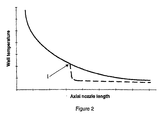
- Fig. 2 shows the curve of the relation between wall temperature and axial length of the nozzle according to the invention.
- Fig. 1 it is thus illustrated a rocket nozzle 1 of so-called “Dual Bell” type, i.e. having an axially double bell shape.
- a rocket nozzle 1 of so-called “Dual Bell” type i.e. having an axially double bell shape.
- the inflection point might be located at any suitable location between the two stipulated limits stated above.
- the sudden acceleration of the film flow along the wall caused by the change of curvature of the wall contour line provides for an improved cooling effect starting immediately downstream said inflection point and maintaining said effect to such an extent that the rest of the wall downstream said inflection point will be kept almost constant. Said reduced wall temperature thus allows the use of a wall material not at all as temperature resistant as requested in prior art and consequently a cheaper structure.
Landscapes
- Engineering & Computer Science (AREA)
- Chemical & Material Sciences (AREA)
- Combustion & Propulsion (AREA)
- Mechanical Engineering (AREA)
- General Engineering & Computer Science (AREA)
- Nozzles (AREA)
- Aerodynamic Tests, Hydrodynamic Tests, Wind Tunnels, And Water Tanks (AREA)
- Inorganic Compounds Of Heavy Metals (AREA)
Description
Claims (1)
- A rocket nozzle having axially double bell shape, i.e. of so-called "Dual Bell" type, and having an outwardly directed change of curvature of the contour line or generatrix at the inflection point between the two bell shapes, the change of curvature amounts to between 2° and 7°, characterized in that for obtaining an improved cooling action on the nozzle wall said inflection point (I) being located between a location at the area ratio ε = 10 and a location at the area ratio ε = 0,85 x εmax of the nozzle.
Applications Claiming Priority (1)
| Application Number | Priority Date | Filing Date | Title |
|---|---|---|---|
| PCT/SE1996/001178 WO1998012429A1 (en) | 1996-09-23 | 1996-09-23 | Controlled temperature rocket nozzle |
Publications (2)
| Publication Number | Publication Date |
|---|---|
| EP0862688A1 EP0862688A1 (en) | 1998-09-09 |
| EP0862688B1 true EP0862688B1 (en) | 2002-06-05 |
Family
ID=20401972
Family Applications (1)
| Application Number | Title | Priority Date | Filing Date |
|---|---|---|---|
| EP96937608A Expired - Lifetime EP0862688B1 (en) | 1996-09-23 | 1996-09-23 | Controlled temperature rocket nozzle |
Country Status (5)
| Country | Link |
|---|---|
| US (1) | US6318071B2 (en) |
| EP (1) | EP0862688B1 (en) |
| JP (1) | JP3924326B2 (en) |
| DE (1) | DE69621638T2 (en) |
| WO (1) | WO1998012429A1 (en) |
Cited By (1)
| Publication number | Priority date | Publication date | Assignee | Title |
|---|---|---|---|---|
| DE102012013399A1 (en) | 2011-08-03 | 2013-02-07 | Hoerbiger Kompressortechnik Holding Gmbh | fluid mixers |
Families Citing this family (7)
| Publication number | Priority date | Publication date | Assignee | Title |
|---|---|---|---|---|
| RU2209333C2 (en) * | 1998-12-04 | 2003-07-27 | Вольво Аэро Корпорэйшн | Conour of rocket nozzle to control division of flow and reduct side load |
| RU2196917C1 (en) * | 2002-02-06 | 2003-01-20 | Федеральное государственное унитарное предприятие "Исследовательский Центр им. М.В. Келдыша" | Liquid-propellant rocket engine chamber |
| US20080264372A1 (en) * | 2007-03-19 | 2008-10-30 | Sisk David B | Two-stage ignition system |
| JP4672747B2 (en) | 2008-03-18 | 2011-04-20 | 三菱重工業株式会社 | Rocket nozzle and rocket engine combustion gas flow control method |
| DE102009025873A1 (en) * | 2009-05-27 | 2010-12-02 | Saar-Metallwerke Gmbh | Use of a height compensating nozzle |
| CN105179109B (en) * | 2015-06-08 | 2017-05-17 | 北京航天动力研究所 | Spraying pipe extending and unfolding mechanism adopting air blowing principle |
| DE102015011958B4 (en) * | 2015-09-18 | 2024-02-01 | Arianegroup Gmbh | Thruster |
Family Cites Families (6)
| Publication number | Priority date | Publication date | Assignee | Title |
|---|---|---|---|---|
| DE897568C (en) * | 1948-01-26 | 1953-11-23 | Condenseurs Delas Soc D | Nozzle for expanding a gas or vapor medium |
| US3423942A (en) * | 1963-09-20 | 1969-01-28 | Us Navy | Standing detonation wave rocket engine |
| US3394549A (en) | 1965-07-06 | 1968-07-30 | North American Rockwell | Step nozzle |
| US3925982A (en) * | 1973-09-11 | 1975-12-16 | Martin Marietta Corp | Fluid-dynamic shock ring for controlled flow separation in a rocket engine exhaust nozzle |
| FR2503794B1 (en) * | 1981-04-13 | 1986-04-25 | Europ Propulsion | MULTIPLE DIVERGENT ROCKET COMBUSTION CHAMBER |
| FR2618488B1 (en) | 1987-07-20 | 1989-12-15 | Europ Propulsion | DIVERGENT WITH BREAKING GALBE FOR NOZZLE OF MOTOR-ROCKET |
-
1996
- 1996-09-23 JP JP51456298A patent/JP3924326B2/en not_active Expired - Fee Related
- 1996-09-23 EP EP96937608A patent/EP0862688B1/en not_active Expired - Lifetime
- 1996-09-23 WO PCT/SE1996/001178 patent/WO1998012429A1/en not_active Ceased
- 1996-09-23 US US09/066,331 patent/US6318071B2/en not_active Expired - Fee Related
- 1996-09-23 DE DE69621638T patent/DE69621638T2/en not_active Expired - Lifetime
Cited By (2)
| Publication number | Priority date | Publication date | Assignee | Title |
|---|---|---|---|---|
| DE102012013399A1 (en) | 2011-08-03 | 2013-02-07 | Hoerbiger Kompressortechnik Holding Gmbh | fluid mixers |
| DE102012013399B4 (en) | 2011-08-03 | 2023-06-29 | Hoerbiger Wien Gmbh | fluid mixer |
Also Published As
| Publication number | Publication date |
|---|---|
| JP3924326B2 (en) | 2007-06-06 |
| DE69621638D1 (en) | 2002-07-11 |
| US6318071B2 (en) | 2001-11-20 |
| EP0862688A1 (en) | 1998-09-09 |
| DE69621638T2 (en) | 2002-11-07 |
| WO1998012429A1 (en) | 1998-03-26 |
| US20010023583A1 (en) | 2001-09-27 |
Similar Documents
| Publication | Publication Date | Title |
|---|---|---|
| US6460807B1 (en) | Missile components made of fiber-reinforced ceramics | |
| US6354074B1 (en) | Hybrid injection thrust vector control | |
| US20030005701A1 (en) | Rocket vehicle thrust augmentation within divergent section of nozzle | |
| US8215097B2 (en) | Rocket thruster assembly comprising load-balanced pintle valve | |
| US6318071B2 (en) | Controlled temperature rocket nozzle | |
| EP1184560B1 (en) | Rocket nozzle assembly having rotatable thrust control cylinders | |
| RU2007607C1 (en) | Annular nozzle of solid-propellant rocket engine | |
| JP2000501475A (en) | Controlled temperature rocket nozzle | |
| Berdoyes | Snecma Propulsion Solide Advanced Technology SRM Nozzles. History and Future. | |
| US7406821B2 (en) | Adapter device for a rocket engine nozzle having a movable diverging portion | |
| US3394549A (en) | Step nozzle | |
| RU2133368C1 (en) | Solid-propellant rocket engine | |
| US4648567A (en) | Directional control of rockets using elastic deformation of structural members | |
| US5154050A (en) | Thrust vector control using internal airfoils | |
| EP0880645B1 (en) | Rocket engine nozzle | |
| RU2156875C2 (en) | Rocket nozzle at adjustable temperature | |
| US6543717B1 (en) | Compact optimal and modulatable thrust device for controlling aerospace vehicles | |
| CN1080823C (en) | Temperature-controlled rocket nozzle | |
| Schoyer | Thrust vector control for (clustered modules) plug nozzles: Some considerations | |
| Berdoyes | SRM nozzle design breakthroughs with advanced composite materials | |
| Dahl et al. | Demonstration of solid propellant pulse motor technologies | |
| US6308514B2 (en) | Rocket engine nozzle | |
| US3285519A (en) | Free expanding displaceable throat insert for a nozzle assembly of a solid propellant rocket motor | |
| RU2159862C2 (en) | Aircraft power unit | |
| RU2145671C1 (en) | Rocket engine nozzle unit |
Legal Events
| Date | Code | Title | Description |
|---|---|---|---|
| PUAI | Public reference made under article 153(3) epc to a published international application that has entered the european phase |
Free format text: ORIGINAL CODE: 0009012 |
|
| 17P | Request for examination filed |
Effective date: 19980508 |
|
| AK | Designated contracting states |
Kind code of ref document: A1 Designated state(s): DE FR GB IT SE |
|
| GRAG | Despatch of communication of intention to grant |
Free format text: ORIGINAL CODE: EPIDOS AGRA |
|
| 17Q | First examination report despatched |
Effective date: 20010801 |
|
| GRAG | Despatch of communication of intention to grant |
Free format text: ORIGINAL CODE: EPIDOS AGRA |
|
| GRAH | Despatch of communication of intention to grant a patent |
Free format text: ORIGINAL CODE: EPIDOS IGRA |
|
| GRAH | Despatch of communication of intention to grant a patent |
Free format text: ORIGINAL CODE: EPIDOS IGRA |
|
| GRAA | (expected) grant |
Free format text: ORIGINAL CODE: 0009210 |
|
| AK | Designated contracting states |
Kind code of ref document: B1 Designated state(s): DE FR GB IT SE |
|
| REG | Reference to a national code |
Ref country code: GB Ref legal event code: FG4D |
|
| RIN1 | Information on inventor provided before grant (corrected) |
Inventor name: PEKKARI, LARS-OLOF Inventor name: HAEGGANDER, JAN |
|
| REF | Corresponds to: |
Ref document number: 69621638 Country of ref document: DE Date of ref document: 20020711 |
|
| ET | Fr: translation filed | ||
| PLBE | No opposition filed within time limit |
Free format text: ORIGINAL CODE: 0009261 |
|
| STAA | Information on the status of an ep patent application or granted ep patent |
Free format text: STATUS: NO OPPOSITION FILED WITHIN TIME LIMIT |
|
| 26N | No opposition filed |
Effective date: 20030306 |
|
| PGFP | Annual fee paid to national office [announced via postgrant information from national office to epo] |
Ref country code: GB Payment date: 20120919 Year of fee payment: 17 Ref country code: SE Payment date: 20120911 Year of fee payment: 17 |
|
| PGFP | Annual fee paid to national office [announced via postgrant information from national office to epo] |
Ref country code: IT Payment date: 20120919 Year of fee payment: 17 Ref country code: DE Payment date: 20120919 Year of fee payment: 17 Ref country code: FR Payment date: 20120926 Year of fee payment: 17 |
|
| REG | Reference to a national code |
Ref country code: SE Ref legal event code: EUG |
|
| PG25 | Lapsed in a contracting state [announced via postgrant information from national office to epo] |
Ref country code: SE Free format text: LAPSE BECAUSE OF NON-PAYMENT OF DUE FEES Effective date: 20130924 |
|
| GBPC | Gb: european patent ceased through non-payment of renewal fee |
Effective date: 20130923 |
|
| REG | Reference to a national code |
Ref country code: DE Ref legal event code: R119 Ref document number: 69621638 Country of ref document: DE Effective date: 20140401 |
|
| REG | Reference to a national code |
Ref country code: FR Ref legal event code: ST Effective date: 20140530 |
|
| PG25 | Lapsed in a contracting state [announced via postgrant information from national office to epo] |
Ref country code: GB Free format text: LAPSE BECAUSE OF NON-PAYMENT OF DUE FEES Effective date: 20130923 |
|
| PG25 | Lapsed in a contracting state [announced via postgrant information from national office to epo] |
Ref country code: DE Free format text: LAPSE BECAUSE OF NON-PAYMENT OF DUE FEES Effective date: 20140401 Ref country code: IT Free format text: LAPSE BECAUSE OF NON-PAYMENT OF DUE FEES Effective date: 20130923 Ref country code: FR Free format text: LAPSE BECAUSE OF NON-PAYMENT OF DUE FEES Effective date: 20130930 |