EP0862501B1 - High entrainment venturi for random orbital sander dust collection - Google Patents
High entrainment venturi for random orbital sander dust collection Download PDFInfo
- Publication number
- EP0862501B1 EP0862501B1 EP95940836A EP95940836A EP0862501B1 EP 0862501 B1 EP0862501 B1 EP 0862501B1 EP 95940836 A EP95940836 A EP 95940836A EP 95940836 A EP95940836 A EP 95940836A EP 0862501 B1 EP0862501 B1 EP 0862501B1
- Authority
- EP
- European Patent Office
- Prior art keywords
- entrainment
- nozzle
- flow
- air
- venturi
- Prior art date
- Legal status (The legal status is an assumption and is not a legal conclusion. Google has not performed a legal analysis and makes no representation as to the accuracy of the status listed.)
- Expired - Lifetime
Links
- 239000000428 dust Substances 0.000 title claims description 7
- 230000007704 transition Effects 0.000 claims description 7
- 238000007599 discharging Methods 0.000 claims description 3
- 230000001939 inductive effect Effects 0.000 claims 1
- 230000000694 effects Effects 0.000 description 7
- 230000002860 competitive effect Effects 0.000 description 4
- 239000012530 fluid Substances 0.000 description 3
- 230000007246 mechanism Effects 0.000 description 2
- 239000002245 particle Substances 0.000 description 2
- 230000003247 decreasing effect Effects 0.000 description 1
- 238000005516 engineering process Methods 0.000 description 1
- 238000011835 investigation Methods 0.000 description 1
- 238000004519 manufacturing process Methods 0.000 description 1
- 239000000463 material Substances 0.000 description 1
- 238000000034 method Methods 0.000 description 1
- 238000000926 separation method Methods 0.000 description 1
- 230000032258 transport Effects 0.000 description 1
- 238000011144 upstream manufacturing Methods 0.000 description 1
Images


Classifications
-
- A—HUMAN NECESSITIES
- A47—FURNITURE; DOMESTIC ARTICLES OR APPLIANCES; COFFEE MILLS; SPICE MILLS; SUCTION CLEANERS IN GENERAL
- A47L—DOMESTIC WASHING OR CLEANING; SUCTION CLEANERS IN GENERAL
- A47L9/00—Details or accessories of suction cleaners, e.g. mechanical means for controlling the suction or for effecting pulsating action; Storing devices specially adapted to suction cleaners or parts thereof; Carrying-vehicles specially adapted for suction cleaners
- A47L9/02—Nozzles
-
- B—PERFORMING OPERATIONS; TRANSPORTING
- B23—MACHINE TOOLS; METAL-WORKING NOT OTHERWISE PROVIDED FOR
- B23Q—DETAILS, COMPONENTS, OR ACCESSORIES FOR MACHINE TOOLS, e.g. ARRANGEMENTS FOR COPYING OR CONTROLLING; MACHINE TOOLS IN GENERAL CHARACTERISED BY THE CONSTRUCTION OF PARTICULAR DETAILS OR COMPONENTS; COMBINATIONS OR ASSOCIATIONS OF METAL-WORKING MACHINES, NOT DIRECTED TO A PARTICULAR RESULT
- B23Q11/00—Accessories fitted to machine tools for keeping tools or parts of the machine in good working condition or for cooling work; Safety devices specially combined with or arranged in, or specially adapted for use in connection with, machine tools
- B23Q11/0042—Devices for removing chips
- B23Q11/0046—Devices for removing chips by sucking
-
- B—PERFORMING OPERATIONS; TRANSPORTING
- B24—GRINDING; POLISHING
- B24B—MACHINES, DEVICES, OR PROCESSES FOR GRINDING OR POLISHING; DRESSING OR CONDITIONING OF ABRADING SURFACES; FEEDING OF GRINDING, POLISHING, OR LAPPING AGENTS
- B24B55/00—Safety devices for grinding or polishing machines; Accessories fitted to grinding or polishing machines for keeping tools or parts of the machine in good working condition
- B24B55/06—Dust extraction equipment on grinding or polishing machines
- B24B55/10—Dust extraction equipment on grinding or polishing machines specially designed for portable grinding machines, e.g. hand-guided
Definitions
- Venturi type vacuum sources commonly used with pneumatic random orbital sanders for dust collection purposes typically provide poor performance.
- SCFM standard cubic feet per minute
- the entrainment ratio is defined as the entrained air flow divided by the supply air flow and is a measure of the efficiency of venturi device. Using this definition, the entrainment ratio of current competitive product is less than 1.
- the required flow rate for full dust evacuation with the random orbital sanders has been determined to be 20 to 25 SCFM (566.4-708 1/min) of vacuum flow.
- US-A-2 789 404 discloses a typical grinding wheel dust collector incorporating a venturi nozzle, according to the preamble of claim 1.
- a high entrainment venturi for dust collection comprising a nozzle having a convergence inlet for discharging a flow of air, an entrainment area adjacent said nozzle, and a diffuser having a throat area for receiving said discharged flow of air and air from said entrainment air; characterised in that said nozzle has a means for reducing the viscous shear layer comprising said shallow convergence inlet followed by a short straight section, said shallow convergence inlet having an arcuate transition from an air supply to a convergence cone formed about a flow axis, and said short straight section having a second arcuate transition from said convergence cone to a constant diameter section of short length.
- a typical venturi consists of three parts; a nozzle 1, a throat area 2, and a diffuser area 3, as shown in Fig. 1.
- the nozzle serves to accelerate the exhaust air of the tool into a high velocity stream of air or a jet.
- the jet then entrains air from the surroundings 4 by means of the "venturi” effect.
- the combined air streams are contained by the throat and are decelerated efficiently by the diffuser 3 to reduce head losses.
- the so called "venturi effect” must be maximized.
- the venturi effect results from forces applied on the surrounding fluid by the jet 10. These forces consist primarily of two types; viscous shear forces and pressure gradients.
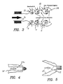
- the viscous shear force is transferred from the jet 10 to the surrounding fluid through the shear layer 6 of the jet as shown in Fig. 2. This shear force is proportional to the gradient of the velocity profile 7 and can thus be increased by thinning the shear layer which increases the velocity gradient.
- the second mechanism driving entrainment or the venturi effect is pressure gradients which drive the surrounding air into the jet 10.
- These pressure gradients arise through the hydrodynamic instability of the jet.
- At the center of the vortical structures exists a low pressure region 12 due to the swirling flow and it is this low pressure region which presents the pressure gradient in relation to the surrounding ambient conditions.
- This phenomena is shown in Fig. 3 and is the topic of much research today by those investigating the nature of turbulence.
- a common finding resulting from these investigations is that the instability and hence the initial strength of the vortical structures can be increased by thinning the shear layer.
- the venturi nozzle 1 Since thinning the shear layer increases both mechanisms that contribute to the venturi effect, the venturi nozzle 1 must be designed to thin the shear layer 6 at the exit in order to maximize entrainment.
- a typical venturi nozzle contains sharp edges at the entrance 21 and long straight sections 22 which increase the thickness of the shear layer at the exit of the nozzle.
- the nozzle design according to the present invention is shown in Fig. 5 and detailed in Fig. 7. Since the velocities upstream of the nozzle are subsonic, the nozzle was shaped with continually decreasing cross sectional area 15 in order to accelerate the fluid and produce the thinnest shear layer possible with minimum back pressure. This is achieved with a conical section 15 followed by a radius 16 and a short section 17 for manufacturing ease.
- Fig. 6 shows a high entrainment venturi nozzle assembly for random orbital sanders designed according to the present invention.
- the nozzle assembly generally designated by the reference numeral 50 comprises a generally offset Y shaped housing constructed of a thermal plastic material or the like.
- the housing is provided with generally circular internal passageways as follows: a vacuum flow passage 51, a venturi nozzle 52, and an exit throat passage 53.
- the vacuum flow passage 51 receives air and entrained particles from the work surface and transports the vacuum flow as smoothly as possible into the venturi nozzle area. Exhaust air from the air motor of the sander is exhausted through the venturi nozzle 1 in passage 52. The exhaust air passing through the nozzle forms the venturi jet required to form the vacuum and hence the vacuum flow.
- the air exiting the nozzle forms the required venturi effect in cooperation with the throat area 2 which is formed in the base of the Y.
- the exhaust air and entrained vacuum flow exit the venturi assembly through passageway 53 into a dust collector typically in the form of a porous bag or the like which permits separation of the exhaust air from the entrained particles collected by the vacuum.
- a nozzle according to the present invention having a nozzle throat 55 diameter of approximately 0.186 inches (4.7244 mm) effectively formed in a venturi nozzle by forming the nozzle restriction using a one-half inch (12.70 mm) radius arcuate transition 56 into a shallow (typically formed utilising a convergence angle 60 approximately .20 degrees from the axis although a useful range is thought to be between 10 and 30 degrees from the axis) convergent cone 57 followed by a second 0.25 inch (6.35 mm) radius arcuate section 58 terminating in a .020 inch (0.508 mm) long straight section forming the nozzle throat of approximately 0.186 inch (4.7244 mm) diameter and finally terminating in a .010 inch (0.254 mm) long 45 degree exit chamfer 59, as detailed in Fig. 7.
- the diffuser 53 is formed with a diffuser throat diameter of approximately 0.520 inches (13.208 mm) and is spaced apart from the nozzle exit so that the natural expansion of the venturi jet tangentially intersects the diffuser throat as shown in Fig. 1.
- a vacuum flow of 24 SCFM was obtained using an exhaust air flow rate for the sander motor of approximately 16 SCFM at an effective average pressure of approximately 5 PSIG - 34.475 kN/m 2 (approximately twice the nearest competitive product) yielding an entrainment ratio of 1.5.
Landscapes
- Engineering & Computer Science (AREA)
- Mechanical Engineering (AREA)
- Jet Pumps And Other Pumps (AREA)
- Grinding-Machine Dressing And Accessory Apparatuses (AREA)
- Nozzles (AREA)
Description
Claims (8)
- A high entrainment venturi for dust collection comprising a nozzle (1) having a convergence inlet for discharging a flow of air, an entrainment area adjacent said nozzle (1), and a diffuser (53) having a throat area (2) for receiving said discharged flow of air and air from said entrainment area; characterised in that said nozzle has a means for reducing the viscous shear layer comprising said shallow convergence inlet (57) followed by a short straight section (55), said shallow convergence inlet (57) having an arcuate transition (56) from an air supply to a convergence cone (57) formed about a flow axis, and said short straight section (55) having a second arcuate transition (58) from said convergence cone (57) to a constant diameter section (55) of short length.
- A high entrainment venturi according to claim 1, wherein the angle of said convergence (60) cone (57) is approximately 20 degrees.
- A high entrainment venturi according to claim 1 or 2, wherein said constant diameter section (55) is followed by a formed exit chamfer (59).
- A high entrainment venturi according to claim 1, 2 or 3, wherein said nozzle (1) discharges a defined air flow having a natural expansion which tangentially intersects said throat area (2) of said diffuser (53).
- A high entrainment venturi according to any one of the preceding claims, wherein said entrainment venturi is in a random orbital sander.
- A high entrainment venturi according to any one of the preceding claims, wherein said discharging flow of air is exhaust air from a sander motor.
- A high entrainment venturi according to any one of the preceding claims, wherein said entrainment area receives a vacuum induced flow.
- A high entrainment venturi according to any one of the preceding claims, wherein said nozzle (1) has a throat diameter of approximately .186 inches (4.7244 mm), a convergence angle (60) of approximately 20 degrees, an arcuate transition (56) having a radius of .5 inches (12.70 mm), a second arcuate transition (58) of .25 inches (6.35 mm), and said diffuser (53) having a throat diameter of .520 inches (13.208 mm), said nozzle (1) receiving a flow of exhaust air from a sander motor in the range of 16 SCFM (453.12 1/min) and inducing an entrainment flow vacuum in the range of 25 SCFM (708 1/min) for an entrainment ratio of 1.5.
Applications Claiming Priority (3)
| Application Number | Priority Date | Filing Date | Title |
|---|---|---|---|
| US08/437,257 US5560547A (en) | 1995-05-08 | 1995-05-08 | High entrainment venturi for random orbital sander dust collection |
| US437257 | 1995-05-08 | ||
| PCT/US1995/015354 WO1996035515A1 (en) | 1995-05-08 | 1995-11-20 | High entrainment venturi for random orbital sander dust collection |
Publications (3)
| Publication Number | Publication Date |
|---|---|
| EP0862501A1 EP0862501A1 (en) | 1998-09-09 |
| EP0862501A4 EP0862501A4 (en) | 1998-09-09 |
| EP0862501B1 true EP0862501B1 (en) | 2002-04-03 |
Family
ID=23735706
Family Applications (1)
| Application Number | Title | Priority Date | Filing Date |
|---|---|---|---|
| EP95940836A Expired - Lifetime EP0862501B1 (en) | 1995-05-08 | 1995-11-20 | High entrainment venturi for random orbital sander dust collection |
Country Status (5)
| Country | Link |
|---|---|
| US (1) | US5560547A (en) |
| EP (1) | EP0862501B1 (en) |
| JP (1) | JPH11511060A (en) |
| DE (1) | DE69526261T2 (en) |
| WO (1) | WO1996035515A1 (en) |
Families Citing this family (9)
| Publication number | Priority date | Publication date | Assignee | Title |
|---|---|---|---|---|
| US5716006A (en) * | 1996-04-15 | 1998-02-10 | Lott; William Gerald | Jet pump having an improved nozzle and a diffuser |
| US6219922B1 (en) * | 1997-06-04 | 2001-04-24 | Black & Decker, Inc. | Nozzle assembly for a power tool |
| US6161627A (en) * | 1999-06-21 | 2000-12-19 | Ingersoll-Rand Company | Particle separator and pneumatic tool incorporating same |
| DE10001983A1 (en) * | 2000-01-19 | 2001-07-26 | Zueblin Ag | Cutting-jet monitor has passage through nozzle carrier directly adjoining fitted nozzles and passage forming symmetric or asymmetric funnel shape |
| US20040060719A1 (en) * | 2002-09-26 | 2004-04-01 | Wiborg Lance W. | Universal suction attachment for pneumatic power tools |
| DE602004011388T2 (en) * | 2003-10-21 | 2008-05-15 | Shell Internationale Research Maatschappij B.V. | Nozzle assembly and method for excavating a hole in an object |
| GB201120159D0 (en) * | 2011-11-23 | 2012-01-04 | Rolls Royce Plc | A swarf extraction tool |
| CN104897437A (en) * | 2015-06-01 | 2015-09-09 | 金川集团股份有限公司 | Automatic sampling device and method for nelson effluent concentrate |
| US10478029B2 (en) | 2017-11-17 | 2019-11-19 | Lockheed Martin Corporation | Exhaust-supplied vacuum system and apparatus |
Family Cites Families (11)
| Publication number | Priority date | Publication date | Assignee | Title |
|---|---|---|---|---|
| US2246916A (en) * | 1940-10-05 | 1941-06-24 | Chicago Pneumatic Tool Co | Hold-down and chip collecting attachment for drills |
| US2349156A (en) * | 1942-03-13 | 1944-05-16 | Chicago Pneumatic Tool Co | Offset drilling attachment |
| US2789404A (en) * | 1955-01-11 | 1957-04-23 | Holman Brothers Ltd | Dust collecting |
| FR1301137A (en) * | 1961-09-07 | 1962-08-10 | Ferdinand Spitznas Maschinenfa | Compressed air machine tool, more particularly transportable machine, such as a hand grinding machine |
| US3625820A (en) * | 1968-06-14 | 1971-12-07 | Gen Electric | Jet pump in a boiling water-type nuclear reactor |
| US3824745A (en) * | 1972-08-21 | 1974-07-23 | A Hutchins | Suction system for abrading tool |
| US3815292A (en) * | 1972-08-21 | 1974-06-11 | A Hutchins | Structure and manufacture of abrading tool having suction system |
| US4052824A (en) * | 1976-11-29 | 1977-10-11 | Hutchins Manufacturing Company | Abrading tool suction system |
| US4285638A (en) * | 1979-07-06 | 1981-08-25 | Dresser Industries, Inc. | Jet pump nozzle assembly |
| FR2575678B1 (en) * | 1985-01-04 | 1988-06-03 | Saint Gobain Vitrage | PNEUMATIC POWDER EJECTOR |
| IT1258820B (en) * | 1992-01-24 | 1996-02-29 | Giuseppe Catalfamo | DISC SANDER WITH EMBEDDED DUST EXTRACTION MEANS |
-
1995
- 1995-05-08 US US08/437,257 patent/US5560547A/en not_active Expired - Lifetime
- 1995-11-20 EP EP95940836A patent/EP0862501B1/en not_active Expired - Lifetime
- 1995-11-20 WO PCT/US1995/015354 patent/WO1996035515A1/en not_active Ceased
- 1995-11-20 DE DE69526261T patent/DE69526261T2/en not_active Expired - Fee Related
- 1995-11-20 JP JP8534030A patent/JPH11511060A/en not_active Ceased
Also Published As
| Publication number | Publication date |
|---|---|
| US5560547A (en) | 1996-10-01 |
| EP0862501A1 (en) | 1998-09-09 |
| DE69526261D1 (en) | 2002-05-08 |
| EP0862501A4 (en) | 1998-09-09 |
| JPH11511060A (en) | 1999-09-28 |
| DE69526261T2 (en) | 2002-11-21 |
| WO1996035515A1 (en) | 1996-11-14 |
Similar Documents
| Publication | Publication Date | Title |
|---|---|---|
| US6283833B1 (en) | Method and apparatus for producing a high-velocity particle stream | |
| US6168503B1 (en) | Method and apparatus for producing a high-velocity particle stream | |
| JPH0359743B2 (en) | ||
| US5560547A (en) | High entrainment venturi for random orbital sander dust collection | |
| EP0526087A1 (en) | Nozzle for abrasive cleaning or cutting | |
| US20090032130A1 (en) | Fluid flow amplifier | |
| US20080014855A1 (en) | Fan | |
| US4026474A (en) | Venturi nozzle for air guns | |
| US4245961A (en) | Ejector utilizing a vortex flow | |
| JP2942168B2 (en) | Method and apparatus for enlarging processing pattern in blast processing | |
| CA2206524C (en) | High entrainment venturi for random orbital sander dust collection | |
| US4422565A (en) | Strip material transporting apparatus | |
| US7422167B2 (en) | Fluid-energy mill | |
| JP3511298B2 (en) | Water jet generation method and apparatus | |
| WO1999002302A1 (en) | Method and apparatus for producing a high-velocity particle stream | |
| RU2057632C1 (en) | Abrasive-jet apparatus | |
| JPH06226145A (en) | Gas-liquid mixing device | |
| RU2161273C1 (en) | Jet-type pump | |
| JPH0724735A (en) | Nozzle assembly for abrasive water jet | |
| SU1337121A1 (en) | Dust separator | |
| JPS5811810Y2 (en) | Yarn suction device | |
| EP0046049A1 (en) | Cyclones | |
| SU1384838A1 (en) | Vortex ejector | |
| JP3175233B2 (en) | Classifier | |
| SU522910A2 (en) | Cutting tool |
Legal Events
| Date | Code | Title | Description |
|---|---|---|---|
| PUAI | Public reference made under article 153(3) epc to a published international application that has entered the european phase |
Free format text: ORIGINAL CODE: 0009012 |
|
| 17P | Request for examination filed |
Effective date: 19970707 |
|
| A4 | Supplementary search report drawn up and despatched |
Effective date: 19980717 |
|
| AK | Designated contracting states |
Kind code of ref document: A4 Designated state(s): DE FR GB Kind code of ref document: A1 Designated state(s): DE FR GB |
|
| GRAG | Despatch of communication of intention to grant |
Free format text: ORIGINAL CODE: EPIDOS AGRA |
|
| 17Q | First examination report despatched |
Effective date: 20010706 |
|
| GRAG | Despatch of communication of intention to grant |
Free format text: ORIGINAL CODE: EPIDOS AGRA |
|
| GRAG | Despatch of communication of intention to grant |
Free format text: ORIGINAL CODE: EPIDOS AGRA |
|
| GRAH | Despatch of communication of intention to grant a patent |
Free format text: ORIGINAL CODE: EPIDOS IGRA |
|
| REG | Reference to a national code |
Ref country code: GB Ref legal event code: IF02 |
|
| GRAH | Despatch of communication of intention to grant a patent |
Free format text: ORIGINAL CODE: EPIDOS IGRA |
|
| GRAA | (expected) grant |
Free format text: ORIGINAL CODE: 0009210 |
|
| AK | Designated contracting states |
Kind code of ref document: B1 Designated state(s): DE FR GB |
|
| REF | Corresponds to: |
Ref document number: 69526261 Country of ref document: DE Date of ref document: 20020508 |
|
| ET | Fr: translation filed | ||
| PLBE | No opposition filed within time limit |
Free format text: ORIGINAL CODE: 0009261 |
|
| STAA | Information on the status of an ep patent application or granted ep patent |
Free format text: STATUS: NO OPPOSITION FILED WITHIN TIME LIMIT |
|
| 26N | No opposition filed |
Effective date: 20030106 |
|
| PGFP | Annual fee paid to national office [announced via postgrant information from national office to epo] |
Ref country code: GB Payment date: 20071128 Year of fee payment: 13 Ref country code: FR Payment date: 20071119 Year of fee payment: 13 |
|
| PGFP | Annual fee paid to national office [announced via postgrant information from national office to epo] |
Ref country code: DE Payment date: 20071221 Year of fee payment: 13 |
|
| GBPC | Gb: european patent ceased through non-payment of renewal fee |
Effective date: 20081120 |
|
| REG | Reference to a national code |
Ref country code: FR Ref legal event code: ST Effective date: 20090731 |
|
| PG25 | Lapsed in a contracting state [announced via postgrant information from national office to epo] |
Ref country code: DE Free format text: LAPSE BECAUSE OF NON-PAYMENT OF DUE FEES Effective date: 20090603 |
|
| PG25 | Lapsed in a contracting state [announced via postgrant information from national office to epo] |
Ref country code: GB Free format text: LAPSE BECAUSE OF NON-PAYMENT OF DUE FEES Effective date: 20081120 |
|
| PG25 | Lapsed in a contracting state [announced via postgrant information from national office to epo] |
Ref country code: FR Free format text: LAPSE BECAUSE OF NON-PAYMENT OF DUE FEES Effective date: 20081130 |