EP0862301A2 - An encryption communication system using an agent and a storage medium for storing that agent - Google Patents
An encryption communication system using an agent and a storage medium for storing that agent Download PDFInfo
- Publication number
- EP0862301A2 EP0862301A2 EP97305086A EP97305086A EP0862301A2 EP 0862301 A2 EP0862301 A2 EP 0862301A2 EP 97305086 A EP97305086 A EP 97305086A EP 97305086 A EP97305086 A EP 97305086A EP 0862301 A2 EP0862301 A2 EP 0862301A2
- Authority
- EP
- European Patent Office
- Prior art keywords
- agent
- agents
- cryptographic processing
- seed
- encryption
- Prior art date
- Legal status (The legal status is an assumption and is not a legal conclusion. Google has not performed a legal analysis and makes no representation as to the accuracy of the status listed.)
- Granted
Links
Images


Classifications
-
- H—ELECTRICITY
- H04—ELECTRIC COMMUNICATION TECHNIQUE
- H04L—TRANSMISSION OF DIGITAL INFORMATION, e.g. TELEGRAPHIC COMMUNICATION
- H04L63/00—Network architectures or network communication protocols for network security
- H04L63/04—Network architectures or network communication protocols for network security for providing a confidential data exchange among entities communicating through data packet networks
- H04L63/0428—Network architectures or network communication protocols for network security for providing a confidential data exchange among entities communicating through data packet networks wherein the data content is protected, e.g. by encrypting or encapsulating the payload
-
- H—ELECTRICITY
- H04—ELECTRIC COMMUNICATION TECHNIQUE
- H04L—TRANSMISSION OF DIGITAL INFORMATION, e.g. TELEGRAPHIC COMMUNICATION
- H04L63/00—Network architectures or network communication protocols for network security
- H04L63/06—Network architectures or network communication protocols for network security for supporting key management in a packet data network
- H04L63/068—Network architectures or network communication protocols for network security for supporting key management in a packet data network using time-dependent keys, e.g. periodically changing keys
-
- H—ELECTRICITY
- H04—ELECTRIC COMMUNICATION TECHNIQUE
- H04L—TRANSMISSION OF DIGITAL INFORMATION, e.g. TELEGRAPHIC COMMUNICATION
- H04L9/00—Cryptographic mechanisms or cryptographic arrangements for secret or secure communications; Network security protocols
- H04L9/40—Network security protocols
Definitions
- This invention is related to an encryption communication method to prevent the theft and interception of, and tampering with, information in communication between computers; in particular, it relates to a method of encryption using an agent.
- the encryption method is public information. For this reason, in order to obtain a strong cryptosystem, the key used in encryption must have a large number of bits. However, when the key used in encryption has a large number of bits, the time required for encryption and decryption processing inevitably becomes long. In particular, when encryption is done in real time applications (such as voice and images) the slowness of the processing in conventional methods such as DES and RSA is a problem.
- a purpose of this invention is to provide a strong encryption method that has adequate processing speed so that in practice there is no problem in real time transfer of data.
- Another purpose of this invention is to make it possible to conduct encrypted communication between terminals without having to preinstall the same encryption program in them.
- An encryption communication method of the present invention is based on the system in which encrypted data are transmitted between a first terminal and a second terminal.
- the method includes the following steps.
- a step for performing an encryption communication between the first agent and the second agent is
- Another feature of the present invention is based on the system in which encrypted data are transmitted among a plurality of terminals.
- the method includes the following steps.
- a step for distributing agents including a program for cryptographic processing from a agent distributing server to the plurality of terminals;
- an agent for the purpose of encryption processing is installed in the sending terminal.
- the sending terminal Before transferring data, the sending terminal sends an agent having the same function as the installed agent to the receiving terminal.
- the agent that is sent to the receiving terminal is described in mobile code.
- the data are encrypted using that agent in the sending terminal, and decrypted in the receiving terminal using the agent that was sent from the sending terminal.
- the encryption and decryption processing are executed by the agent, so it is not necessary for the user to be concerned with the encryption method used for that encrypted communication.
- the encryption and decryption processing are performed by agents having the same functions in both the sending terminal and the receiving terminal, so that the cipher text can be reliably decrypted in the receiving terminal.
- the encryption method can, if desired, be confidential.
- the security of the encryption can be increased by changing the key needed for encryption synchronously in accordance with rules agreed upon in advance between the agents. Therefore, an encryption method with a small overhead can be selected to reduce processing time.
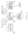
- Fig. 1 is a diagram that explains an outline of this invention. This diagram shows an example in which information is transferred in encrypted form between a server 10 and a client 15.
- the server 10 and the client 15 are both computers.
- the trusted agent 11 has a program for the purpose of encrypting data, and is described in mobile code.
- the trusted agent sending unit 12 sends the trusted agent 11 to the client 15.
- the application program 13 performs processing that accompanies sending data to and receiving data from the client 15.
- Applications which are envisioned in this embodiment include telephone, television conferences, video transmission, etc., all of which require real-time processing, but the possible applications are not limited to these.
- the trusted agent 14 is an encrypted program that has the same function as the trusted agent 11; it resides permanently in the server 10.
- the application program 16 is basically the same as the application 13.
- the trusted agent 17 is the trusted agent 11 that was transferred from the server 10.
- the encrypted communication path 18 is a path established between the trusted agent 14 and the trusted agent 17.
- Fig. 2 is a configuration diagram of the server 10 and the client 15.
- the storage device 501 consists of a semiconductor memory, a magnetic recording medium or an optical recording medium and so on, and stores programs, data, etc.
- the storage device 501 can be permanently installed in the server 10 or the client 15, or it can be removable.
- the storage medium driver 502 is a device that reads out data stored in the portable storage medium 503 (including a semiconductor memory, magnetic disc, optical disc, magneto-optical disc, etc.), or writes data into the portable storage medium 503.
- the communication control unit 504 is a unit that controls the sending of data to and receiving of data from a network.
- the CPU 505 loads programs from the storage device 501 or the portable storage medium 503 into the memory 506 and executes them.
- programs and data stored in the storage medium 501 may have been written in from the portable storage medium 503, or may be received from another machine on a network via a communication line.
- the configuration may also be such that the CPU 505 can use programs and data stored in another storage device on a network via a communication line.
- the trusted agents 11 and 14 are prestored in the storage device 501 in the server 10.
- the trusted agents 11 and 14 may be installed from the portable storage medium 503 into the storage device 501, or may be installed from another device on a network into the storage device 501.
- the trusted agent 14 is loaded into the memory 506 when an encrypted communication is started.
- the trusted agent 17 is received via the communication control section 504 and loaded into the memory 506.
- the action of the cryptosystem shown in Fig. 1 is as follows. First, before the data communication, the trusted agent sending unit 12 is started up and the trusted agent 11 is sent from the server 10 to the client 15. At this time, the trusted agent 11 is encrypted by a method such as RSA or RSA+DES and transferred.
- the processing speeds of RSA, DES, etc. are slow, so they are not the best encryption methods to use for encrypting data that require real time processing such as audio data and video data, but when encrypting a trusted agent, the encryption processing and the decryption processing each only have to be done once, and the amount of data is much less than in the cases of audio data and video data, so that even in the cases of RSA and DES the processing speed does not become a problem.
- the trusted agent 14 of the server 10 and the trusted agent 17 of the client 15 establish the encrypted communication path 18.
- the processing by which the trusted agent 11 is transferred from the server 10 to the client 15, and the processing by which the encrypted communication path 18 between the trusted agent 14 and the trusted agent 17 is established, will be explained later.
- the trusted agents 14 and 17 are linked to the application programs 13 and 16, respectively; they encrypt data so that the data cannot be stolen or tampered with, then send and receive the data to/from each other.
- the encryption between the trusted agent 14 and the trusted agent 17 follows the method described in the programs included in the trusted agents 14 and 17.
- the trusted agents 14 and 17 can synchronously change the key (a confidential key) necessary for encryption in accordance with a predetermined rule. This increases the strength of the encryption.
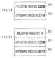
- Fig. 3 is a configuration diagram of the trusted agent 11 described in mobile code.
- the trusted agent 11 consists of an application interface section 11-1 and a cryptographic processing section 11-2.
- the application interface section 11-1 has the role of exchanging signals between an ordinary application program (here, application 16) and the cryptographic processing section 11-2; the cryptographic processing section 11-2 encrypts and decrypts signals to/from the application interface section 11-1.
- Another function that the application interface section 11-1 has is to absorb differences due to different operating systems when the API depends on the operating system.
- the trusted agent 11 has an application program section 11-3.
- the application program stored in the trusted agent 11 is described in mobile code, and the application program section 11-3 is transmitted together with the application interface section 11-1 and the cryptographic processing section 11-2.
- Fig. 4A is a sequence diagram that explains the processing by which a trusted agent is sent and an encrypted communication path is established.
- the server 10 is the terminal that sends the trusted agent
- the client 15 is the terminal that receives the trusted agent.
- the encryption method uses pseudo random numbers. As will be explained in detail later, the pseudo random numbers are generated based on an "initial seed”.
- an initial seed is generated in the server 10.
- the initial seed is, for example, generated based on the time.
- that initial seed is set in the trusted agents 11 and 14.
- the trusted agent 11 in which the initial seed has been set is sent to the client 15.
- the trusted agent 11 is transferred after having been encrypted by the RSA or DES method.
- the server 10 starts the trusted agent 14.
- the trusted agents 14 and 17 establish a encrypted communication path; after that, cipher text is sent and received via that encrypted communication path.
- Fig. 4B is a diagram that explains the procedure by which a encrypted communication path between trusted agents is established.
- the cryptographic processing sections of the trusted agents 14 and 17 each consist of a sending section and a receiving section.
- the sending section encrypts data from an application program and performs send processing; the receiving section converts encrypted data to plain text or appropriate application data and performs processing to transfer the data to an application program.
- the sending section and the receiving section are realized by, for example, threads.
- the sending section of the trusted agent 14 sends a request for connection to the receiving section of the trusted agent 17. If, for example, the transmission path is an ethernet, this connection request is transferred by a TCP packet. Since, at this time, the connection request will be refused if the trusted agent 17 has not been started up, in this case the sending section of the trusted agent 14 repeatedly issues the connection request until a response is received from the receiving section of the trusted agent 17.
- the receiving section of the trusted agent 17 sends a response message in response to the connection request and the receiving section of the trusted agent 14 receives that message, a path is established between the sending section of the trusted agent 14 and the receiving section of the trusted agent 17.
- the procedure for establishing a path between the sending section of the trusted agent 17 and the receiving section of the trusted agent 14 is similar.
- the sending section of the trusted agent 14 encrypts data from the application program 13 and then sends the encrypted data to the trusted agent 17 via the path that has been established.
- the receiving section of the trusted agent 17 decrypts the received cipher text or encrypted data and transfers the resulting plain text or appropriate application data to the application program 16.
- the procedure for sending encrypted data in the opposite direction is similar.
- the encrypted data are, for example, stored in a UDP packet and then transferred.
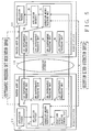
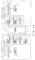
- Fig. 5 is a configuration diagram of the encrypted communication system of one embodiment of this invention.
- the workstations 20 and 30 correspond to the server 10 and the client 15, respectively, in Fig. 1.
- the application programs 21 and 31 correspond to the application programs 13 and 16, respectively, in Fig. 1.
- the trusted agents 22 and 32 correspond to the trusted agents 14 and 17 in Fig. 1, respectively.
- the workstation 20 and the workstation 30 are connected to each other via the Internet 19.
- the trusted agent 22 has the cryptographic processing units 26 to 29. Each of the cryptographic processing units 26 to 29 encrypts data by a different method from the others.
- the encryption method selection unit 24 selects one of the cryptographic processing units 26 to 29 in accordance with an instruction from the encryption method selection control unit 25, and transfers data received via the application interface section 23 to the selected cryptographic processing unit.
- the encryption method selection control unit 25 generates and outputs an instruction signal for the purpose of selecting one from among the cryptographic processing units 26 to 29 in accordance with a specified algorithm. The method by which this instruction signal is generated will be described below.
- the application interface section 23 is basically the same as the application interface section 11-1 shown in Fig. 3A and Fig. 3B.
- the trusted agent 32 has been transferred from the workstation 20.
- the application interface unit 33, the encryption method selection unit 34 and the cryptographic processing units 35 to 38 are basically the same, respectively, as the application interface unit 23, the encryption method selection unit 24 and the cryptographic processing units 26 to 29 which make up the trusted agent 22.
- the trusted agent 32 does not have a unit corresponding to the encryption method selection control unit 25; the encryption method selection unit 34 selects one of the cryptographic processing units 35 to 38 in accordance with an instruction signal generated by the encryption method selection control unit 25.
- the action of the encrypted communication system shown in Fig. 5 is as follows. First, the trusted agent 32 that is described in mobile code is encrypted and transferred from the workstation 20 to the workstation 30.
- the encryption method selection control unit 25 transfers information instructing which encryption method is to be used to the encryption method selection unit 24, and to the encryption method selection unit 34 of the workstation 30. This secures the encrypted communication path.
- the encryption method selection control unit 25 selects the first encryption method, then, as shown in Fig. 5, in the workstation 20 data are encrypted using the 1st cryptographic processing unit 26, and in the workstation 30 the cipher text or encrypted data is decrypted using the 1st cryptographic processing unit 35.
- Communication data from the application program 21 are encrypted in the cryptographic processing unit selected by the encryption method selection unit 24 via the application interface unit 23.
- the example shown in Fig. 5 shows the case in which the 1st cryptographic processing unit 26 has been selected.
- the encrypted data are sent to the workstation 30 via the Internet 19.
- Data (cipher text or encrypted data) received by the workstation 30 are decrypted in the cryptographic processing unit selected by the encryption method selection unit 34 (in this example, the 1st cryptographic processing unit 35), and transferred to the application program 31 in the workstation 30 via the application interface unit 33.
- Data transmission from the application program 31 in the workstation 30 to the application program 21 in the workstation 20 is carried out by a similar encryption procedure.
- the encryption method selection control unit 25 selects new encryption methods at regular or irregular intervals, and posts the selection results to the encryption method selection unit 24 of the workstation 20 and the encryption method selection unit 34 of the workstation 30.
- the encryption method changes with time, making it difficult to decipher the encrypted data.
- the encryption method selection control unit 25 is provided in the workstation 20, but it is also possible to, for example, install an encryption method instruction server on the network, and to have the trusted agents switch their encryption methods based on instructions from that encryption method instruction server.
- the cryptographic processing units are within the trusted agents, but it is also possible to install a cryptographic processing unit distribution server that distributes programs for the purpose of cryptographic processing described in mobile code on a network, and to have programs for the purpose of cryptographic processing distributed from the cryptographic processing unit distribution server to the trusted agents.
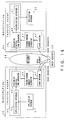
- Fig. 6 is a configuration diagram of the encrypted communication system of another embodiment of this invention.
- the previous explanations apply without change to components to which the same symbols that were used in Fig. 5.
- the encryption method selection control unit 39 is provided in the trusted agent 32.
- the encryption method selection control unit 39 is the same as the encryption method selection control unit 25 within the trusted agent 22. Consequently, the trusted agent 32 can select the same encryption method by itself as the encryption method selected by the trusted agent 22 without receiving an instruction for the purpose of encryption method selection from the trusted agent 22.
- the trusted agent 32 is transferred from the workstation 20 to the workstation 30. This processing is as explained with reference to Fig. 5.
- the encryption method selection control unit 25 in the workstation 20 and the encryption method selection control unit 39 in the workstation 30 determine their respective encryption methods independently of one another, and post those respective encryption methods that have been determined to the encryption method selection unit 24 of the workstation 20 and the encryption method selection unit 34 of the workstation 30, respectively.
- the encryption method selection control units 25 and 39 have synchronization functions in the encryption method selection, so that the same encryption method is selected by the encryption method selection control units 25 and 34.
- the encryption method selection control units 25 and 39 respectively output results obtained in accordance with given initial conditions.
- the initial conditions given to the encryption method selection control unit 39 are set in the workstation 20. These initial conditions are the same as those given to the encryption method selection control unit 25. In Fig. 4, which was discussed above, the same initial seeds were set in 2 trusted agents as initial conditions.
- the encryption method selection control units 25 and 39 have the same functions as one another, so that when the encryption method selection control units 25 and 39 are given the same initial conditions, they will generate the same results. Consequently, the encryption method selection control units 25 and 39 act independently of each other, but output the same values as signals that indicate the encryption method to be used. This is called synchronization in the selection of the encryption method.
- the same encryption method is always selected in the workstation 20 and the workstation 30, without the sending and receiving of information between them. This secures an encrypted communication path.
- the system shown in Fig. 6 is different from the system shown in Fig. 5 in that the encryption method selection control units 25 and 39 are mutually independent and the encryption methods are sequentially selected.
- the encryption method selection control units 25 and 39 select new encryption methods at regular or irregular intervals, and send those selection results to the encryption method selection unit 24 and the encryption method selection unit 34, respectively.
- the encryption method is changing with time, making it hard to decipher the encrypted data.
- Fig. 7 shows an example of configuration of a cryptographic processing unit. The following discussion assumes that pseudo random numbers are being used in the encryption method.
- the cryptographic processing unit consists of an exclusive logical sum generator 40 and a pseudo random number generator 41.
- the pseudo random number generator 41 may be a variable period type.
- the encrypted data (cipher text) are obtained by inputting the data to be encrypted (plain text) and pseudo random numbers generated by the pseudo random number generator 41 into the exclusive logical sum generator 40.
- the configuration is basically the same when the cipher text is decrypted into plain text.
- Fig. 7B shows another example of a cryptographic processing unit.
- the cryptographic processing unit has, in addition to the exclusive logical sum generator 40 and the pseudo random number generator 41, a seed section 42 that generates seeds for the purpose of generating pseudo random numbers and a seed changing section 43 that outputs instructions to change the seeds that are generated in the seed section 42 at irregular intervals.
- the period of the pseudo random numbers can be changed by providing the seed section 42 and the seed changing section 43, making it hard to decipher the encrypted data.
- the action by which plain text is encrypted using the exclusive logical sum generator 40 and the pseudo random number generator 41 is the same as in the case shown in Fig. 7A.
- the period of the pseudo random number generator is determined by, for example, changing the number of stages and the wiring in the linear feedback shift register system that generates the pseudo random numbers.
- Fig. 8 shows a case in which one embodiment of a pseudo random number generator is realized by a hardware circuit.
- 44 is a shift register
- 45 is a path control section
- s0 to s12 and sa to sl are switches for path connection
- x1 to x12 are exclusive logical sum circuits
- r1 to r13 are bit elements of the shift register 44.
- the signal generated by the path control section 45 is used, and the period of the pseudo random numbers is changed by controlling the feedback of r1 to r13 in the shift register 44, by controlling the connection and disconnection of the paths by means of the switches s0 to s12 and the switches sa to sl.
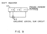
- a pseudo random number generator that generates a 3-stage M series.
- a primitive polynomial that generates a 3-stage M series is x 3 +x+1; the hardware configuration is as shown in Fig. 9.
- 44 is a shift register and 46 is an exclusive logical sum circuit. Consequently, in the pseudo random number generator shown in Fig. 8, in order to realize the configuration shown in Fig. 9, the switch s2 and the switch sb are set to ON, and the other switches are set to OFF.
- the output of the pseudo random number generator shown in Fig. 8 is used as is as pseudo random numbers.
- the 2 outputs of the pseudo random number generator 41a and the pseudo random number generator 41b are input to the exclusive logical sum circuit 47, and the output of that exclusive logical sum circuit 47 is used as the pseudo random numbers.
- the 3 pseudo random number generators 41c, 41d and 41e and the switch 48 are used; the outputs from the 2 pseudo random number generators 41c and 41d are input to the switch 48.
- the output of the pseudo random number generator 41e is used to control the switch 48 and select the output of either the pseudo random number generator 41c or the pseudo random number generator 41d. Then the output of the switch 48 is used as the pseudo random numbers.
- the trusted agents shown in Fig. 5 and Fig. 6 have a plurality of cryptographic processing units; it is possible to, for example, use the random number generation systems shown in Fig. 10A to 10C as the pseudo random number generation sources in the first, second and third cryptographic processing units, respectively.
- Fig. 11 is a flow chart that shows the action of an encryption method selection control unit. Here we explain the action of the encryption method selection control unit 25 in Fig. 5.
- step S1 an initial seed is created based on the time, date, day of the week, etc. shown by the internal clock in the workstation 20. This initial seed is set inside the encryption method selection control unit 25.
- step S2 a pseudo random number generator is used to generate pseudo random numbers from the initial seed created in step S1.
- step S3 the encryption method is selected based on the pseudo random numbers generated in Step S2.
- step S4 information that identifies the encryption method selected in step S3 is transferred to the encryption method selection units 24 and 34.
- step S5 the timing with which the encryption method is switched is determined. This switching timing will be explained in more detail below; it is expressed in terms of a parameter such as number of packets or time.
- step S6 whether or not the cryptographic processing sequence has reached the time for changing the encryption method is monitored. When the cryptographic processing sequence reaches the time for switching the encryption method, the pseudo random number that was generated immediately preceding that time is set as the seed in step S7, and then the procedure returns to step S2. After that, steps S2 to S7 are repeated.
- the encryption method is selected according to the pseudo random number; the encryption method is then repeatedly switched according to the timing determined by the pseudo random numbers.
- pseudo random numbers as opposed to true random numbers, once the initial seed and the generation algorithm are determined, the pseudo random numbers that will be obtained from that generation algorithm are uniquely determined. In the configuration shown in Fig. 6, this property of pseudo random numbers is used. That is to say, since the trusted agents 22 and 32 have pseudo random number generators having the same algorithms, as described above, if the same values are set as initial seeds, after that the encryption method will be switched with the same timing in the trusted agents 22 and 32.
- the trusted agent 32 is transferred to the workstation 30.
- the configuration can be such that a command to generate the initial seed is inserted into the trusted agents 22 and 32, and the trusted agents 22 and 32 then generate their initial seeds independently.
- the command is one that generates the initial seed in accordance with "today's date" and "the present time”
- the command is one that generates the initial seed in accordance with "today's date" and "the present time”
- identical random numbers will be generated in the trusted agents 22 and 32, and the same encryption methods will be selected.
- the data from application program 21 are segmented for the purpose of storage in packets.
- UDP User Datagram Protocol
- data are encrypted by the specified method, one segment at a time.
- a sequence number is assigned to each data segment. The sequence numbers are used so that cryptographic synchronization can be established between the sending side and the receiving side even if a packet should be lost. That is to say, the UDP protocol is appropriate when data requiring real time processing such as audio data and video data are transmitted, but since it does not have a resending function, if a packet is lost in transmission it will become impossible to reproduce the data on the receiving side. For this reason, a sequence number is assigned to each data segment, so that the receiving side can detect the loss of packets and reproduce the data correctly.
- a header is added and sent to the workstation 30.
- An example of a packet configuration is shown in Fig. 12B. The sequence numbers and the header are not encrypted.
- the trusted agent 22 does the encryption processing and the processing to assign sequence numbers. It is possible to expand the functions of the trusted agent 22 so that all of the processing shown in Fig. 12A is executed by the trusted agent 22.
- the workstation 30 When the workstation 30 receives a packet, whether or not a packet has been lost in transmission is judged from its sequence number. If no loss is detected, the encrypted data section is extracted and the data are decrypted. Then the decrypted data are assembled and transferred to the application program 31.
- the trusted agent 32 performs the processing to check the sequence numbers and the decryption processing. It is possible to expand the functions of the trusted agent 32 so that the trusted agent 32 executes all of the processing shown in Fig. 13.
- Fig. 14 is a diagram to explain the method of establishing cryptographic synchronization.
- the trusted agents 22 and 32 generate the same pseudo random numbers in the same sequence with the same timing, and execute encryption and decryption processing in their respective sequences. This establishes cryptographic synchronization.
- a packet has been lost in transmission, then, as shown in Fig. 14A, which packet has been lost is detected on the decryption side, and the decryption processing using the pseudo random number corresponding to the packet that was lost is skipped.
- packet 3 has been lost; on the decryption side, random(3) is not used, but instead decryption processing using random(4) is performed with respect to packet 4.
- the order of received packets is monitored on the decryption side; when loss or interchange of order occurs, synchronization of encryption processing and decryption processing is maintained by skipping decryption processing. This synchronization processing is carried out also in case the first packet is lost.
- Fig. 15 shows an example of the configuration of an encrypted communication system having the capability to change the seed used to generate pseudo random numbers.
- the workstations 50 and 54 correspond to the server 10 and the client 15, respectively, in Fig. 1.
- the application programs 51 and 55 correspond to the application programs 13 and 16, respectively, in Fig. 1.
- the trusted agents 52 and 56 correspond to the trusted agents 14 and 17, respectively, in Fig. 1.
- the trusted agent 52 has an application interface unit 53, and, as were explained referring to Fig. 7B, an exclusive logical sum generator 40, a pseudo random number generator 41, a seed section 42 and a seed generating section (seed changing section) 43.
- the trusted agent 56 has an application interface unit 57, and an exclusive logical sum generator 40', a pseudo random number generator 41' and a seed section 42'.
- the exclusive logical sum generator 40, the pseudo random number generator 41 and the seed section 42, and the exclusive logical sum generator 40', the pseudo random number generator 41' and the seed section 42' are respectively the same type of units.
- the action of the encrypted communication system shown in Fig. 15 is as follows. First, the trusted agent 56 that is described in mobile code is transferred from the workstation 50 to the workstation 54. Next, the seed generating section 43 creates 1 seed and transfers that seed to the seed sections 42 and 42', respectively. At this time, a encrypted communication path between the trusted agents 52 and 56 is established.
- the seed sections 42 and 42' input the seeds that they have received to the pseudo random number generators 41 and 41', respectively. That is to say, the seeds input to the pseudo random number generators 41 and 41' are the same as one another.
- the pseudo random number generators 41 and 41' generate pseudo random numbers in accordance with the respective received seeds and input them to the exclusive logical sum generators 40 and 40'.
- the pseudo random numbers generated in the two units at this time are the same as one another.
- the seed generating section 43 generates new seeds at regular or irregular intervals in accordance with the specified algorithm and transfers them to the seed sections 42 and 42'. Consequently, the same pseudo random numbers are generated in the trusted agents 52 and 56.
- Data from the application program 51 are sent to the exclusive logical sum generator 40 via the application interface unit 53. There the data are encrypted using the pseudo random numbers generated by the pseudo random number generator 41. The encrypted data are sent to the workstation 54 via the Internet 58. The data received by the workstation 54 are decrypted in accordance with the pseudo random numbers generated by the pseudo random number generator 41' in the exclusive logical sum generator 40'. Then those decrypted data are transferred to the application program 55 via the application interface unit 57.
- the action of generating the pseudo random numbers is mutually synchronized in the trusted agents 52 and 56, so that data encrypted in the trusted agent 52 are decrypted in the trusted agent 56.
- Fig. 16 shows an example of configuration of another embodiment of this invention.
- the trusted agent 52 does not have a seed generating section 43; seeds are generated in a seed server 59 connected to the Internet 58.
- the seed server 59 has functions equivalent to those of the seed generating section 43 in Fig. 15; new seeds are generated at regular or irregular intervals and transferred to the seed sections 42 and 42'.
- the action of this system is as follows. First, the trusted agent 56 that is described in mobile code is transferred from the workstation 50 to the workstation 54. Next, the seed section 42 of the workstation 50 requests the seed server 59 for a seed that is needed for encrypted communication. As this time, the trusted agent 52 notify the seed server 59 of the corresponding terminal of the encrypted communication (here, the workstation 54). The seed server 59 generates a seed in accordance with this request, and transfers the generated seed to the seed sections 42 and 42'. This secures an encrypted communication path. The seed server 59 subsequently generates new seeds at regular or irregular intervals and transfers them to the seed sections 42 and 42'. Other action is the same as that described in Fig. 15.
- Fig. 17 shows an example of the configuration of another embodiment of this invention.
- the trusted agents 52 and 56 have the seed generating sections 43 and 43', respectively.
- the seed generating sections 43 and 43' have the same functions as one another.
- the actions of the seed generating sections 43 and 43' are synchronized with each other. That is to say, the same initial values are set in the seed generating sections 43 and 43', and subsequently they output the same seeds in sequence.
- the synchronization between the seed generating sections 43 and 43' is basically the same as the synchronisation between the encryption method selection control units 25 and 39 shown in Fig. 6.
- the action of the system shown in Fig. 17 is as follows. First, the trusted agent 56 that is described in mobile code is transferred from the workstation 50 to the workstation 54. Next, the seeds generated by the seed generating sections 43 and 43' are transferred to the seed sections 42 and 42', respectively, thus securing an encrypted communication path. At this time, the seed generating sections 43 and 43' output the same seeds in the same order. Other actions are as explained with reference to Fig. 15.
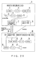
- Fig. 18 is a flow chart that explains the action of a seed generating section or seed server. This processing is basically the same as that in the flow chart in Fig. 11, which selects the encryption method.
- the initial seed is set in step S11.
- the method of setting the initial seed is as was explained with reference to Fig. 11.
- step S12 pseudo random numbers are generated using the pseudo random number generator based on that initial seed.
- steps S13 and S14 the generated random numbers are sent to the seed section as appropriate seeds.
- step S15 the timing at which the seed is changed is determined. This change timing is shown by, for example, a parameter such as number of packets or time.
- step S16 whether or not the time has reached the seed changing timing is monitored.
- the timing to change the seed is reached, in step S17 the immediately preceding generated pseudo random number is set as the new seed, and the procedure returns to step S12. After that, steps S12 to S17 are repeated.
- the seed is changed at irregular intervals according to the processing described above.
- the seed generating section 43 executes the processing described above.
- the seed server 59 executes the processing described above.
- the seed generating sections 43 and 43' respectively execute the processing described above.
- the exclusive logical sum generator 40, the pseudo random number generator 41 seed section 42, and the seed generating section 43; and the exclusive logical sum generator 40', the pseudo random number generator 41' and seed section 42', and the seed generating section 43' respectively have the same functions as one another, so that by setting the same initial seed in the seed generating sections 43 and 43', the same pseudo random numbers are subsequently generated in the same order.
- Fig. 19 is a configuration diagram for the case in which the encrypted communication system of this embodiment is matched to the WWW (World Wide Web).
- the server side software consists of the WWW server 60, the permanently resident trusted agent 61, and the Applet 62 into which cryptographic processing units have been incorporated.
- the Applet 62 is an agent with cryptographic processing.
- the client side software is the WWW browser 63.
- the trusted agent 61 corresponds to the trusted agent 14 in Fig. 1.
- the Applet 62 is described in mobile code and corresponds to the trusted agent 11 in Fig. 1.
- the action of this system is as follows. First, in the client side WWW browser 63, access to the WWW server 60 is performed; then the Applet 62 into which the cryptographic processing units are incorporated are transferred from the server side to the client side and that Applet 62 is incorporated into the WWW browser 63.
- the procedure by which an encrypted communication path is established between the trusted agent 61 and the Applet 62 is, for example, as shown in Fig. 4.
- the data sent from the WWW server 60 in response to that request are encrypted by the trusted agent 61, and sent to the client side.
- the cipher text that has been transferred via the encrypted communication path 64 is received by the Applet 62.
- the Applet 62 knows a method to decrypt the data that were encrypted by the trusted agent 61.
- the Applet 62 decrypts the cipher text received from the WWW server 60, and transfers those decrypted data to the browsing software of WWW browser 63.
- data transmitted from the WWW server 60 to the WWW browser 63 are encrypted by the trusted agent 61 before being sent, and then are decrypted and reproduced by the Applet 62.
- Fig. 20 shows an example of the configuration in the case in which the encrypted communication of this invention corresponds to a video transmission system or an audio transmission system.
- a trusted agent into which the cryptographic processing units are incorporated (a trusted agent with cryptographic processing) is used in combination with applications for video transmission and audio transmission.
- the workstation 70 from which the audio data and the video data are sent consists of the camera 71, the analogue/digital (A/D) converter 72, the frame buffer 73, the microphone 74, the analogue/digital (A/D) converter 75, the buffer 76 and the permanently resident type trusted agent 77 that has a video data/audio data encryption function.
- the trusted agent 78 in which the decryption function corresponding to the encryption processing in the trusted agent 77 is described in mobile code.
- the workstation 80 that receives the video data/audio data consists of the trusted agent 78, into which cryptographic processing units are incorporated, sent from the sending side workstation 70; the frame buffer 82; the digital/analogue (D/A) converter 83; the display 84; the audio data reception buffer 85; the digital/analogue (D/A) converter 86 and the speaker 87.
- the action in this system when video data are sent and received is as follows. First, a request to send the trusted agent 78 is sent from the workstation 80 that wants to receive the video data to the sending side workstation 70. When the sending side workstation 70 receives this send request, it sends the trusted agent 78 that is needed when image data are decrypted to the receiving side workstation 80. This completes the preparation for data transfer.
- the sending side workstation 70 converts the image data taken in from the camera 71 into a digital signal by means of the analogue/digital converter 72 and sends it to the frame buffer 73.
- the frame buffer 73 stores the data from the analogue/digital converter 72 to absorb the difference between the rate at which data are input from the camera 71 and the encryption processing rate in the trusted agent 77.
- the output data from the frame buffer 73 are encrypted by the trusted agent 77 and sent out to the network.
- the encrypted image data that were sent are received and decrypted by the trusted agent 78.
- the decrypted image data are reconverted to an analogue signal by the digital/analogue converter 83 via the receiving side frame buffer 82 and displayed on the display 84.
- the action in the case of transmission of audio data is almost the same as that described above. That is to say, the real time data that are transferred are audio data rather than video data, the microphone 74 replaces the camera 71 as the input section for the data to be transferred, and the speaker 87 replaces the display 84 as the output section. Otherwise the action is basically the same.
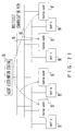
- Fig. 21 is a configuration diagram for the case in which the encrypted communication of this invention is used in an electronic conferencing system.
- an agent distributing station 90 and a plurality of hosts 91 to 94 are mutually interconnected via a network 95.
- the agent distributing station 90 has a user recognition function and distributes agents in response to requests from official users.
- the network 95 is, for example, a LAN.
- the multicast communication path 96 is a transmission path for sending and receiving data among the hosts 91 to 94 during an electronic conference.
- the multicast communication path 96 can be established within the network 95, or it can be established on other physical lines separate from the network 95.
- a host that participates in an electronic conference requests the agent distributing station 90 to send an agent that is needed for encrypted communication in order to establish an encrypted communication path. That is to say if, for example, the hosts 91 to 94 are participating in an electronic conference, one among those hosts posts a member that is participating in the electronic conference to the agent distributing station 90.
- the agent distributing station 90 then sends a trusted agent in which cryptographic processing units are incorporated to the host that made the request.
- the trusted agents 97 that are distributed to the respective hosts 91 to 94 secure encrypted communication paths among those hosts using the multicast communication path 96. Subsequently, data relating to the electronic conference are sent and received in encrypted form.
- the agent distributing station 90 can be configured so that it also serves the function(s) of the encryption method instruction server and/or the encryption processing unit distribution server described with reference to Fig. 5, or for example the seed server 59 shown in Fig. 16.
- Fig. 22A we envision a case in which data are sent and received between the information processing unit 10 (the server in Fig. 1) and the information processing unit 15 (the client in Fig. 1).
- the information processing unit 15 among the settings of the application program 13 in the information processing unit 10, the information processing unit 15 is specified as the communication partner, and a port through which the application program 16 receives data is specified as the communication port.
- the information processing unit 10 is specified as the communication partner, and a port through which the application program 13 receives data is specified as the communication port.
- the same unit (the information processing unit 10) is specified as the communication partner, and a port through which the trusted agent 14 receives data is specified as the communication port.
- the same unit (the information processing unit 15) is specified as the communication partner, and a port through which the trusted agent 17 receives data is specified as the communication port.
- data sent and received between the application programs 13 and 16 are transmitted via the trusted agents 14 and 17. That is to say, the data sent and received by the application programs 13 and 16 can be encrypted merely by changing settings such as the communication ports, without changing the application programs 13 and 16 themselves.
- the proxy (communication routing port) setting is basically changed the same way as the communication partner and communication port described above. That is to say, if there is a function to set the proxy in an application program, the information processing unit in which that application program is installed and a port through which the trusted agent installed in that information processing unit receives data, are set as the proxy.
- the API Application Interface
- the API is used rather than the API provided by the system. In this case, normally it is necessary to recompile after the source program is changed. For example, if there is no trusted agent, the section in which "open();" appears, while if there is a trusted agent, the section should be changed "openTrusted();” is changed, and then the source program is recompiled.
- a trusted agent of this embodiment can be realized as a kernel module of the operating system (OS), and to be incorporated into the OS as necessary.
- OS operating system
- the trusted agent 14 it is also possible for the trusted agent 14 to be incorporated at kernel level of the OS that is installed in the information processing unit 10.
- a trusted agent has an application interface section and a cryptographic processing section.
- the cryptographic processing section consists of a sending section and a receiving section.
- the sending section has a data encryption function, while the receiving section has a cipher text decryption function.
- a trusted agent that is described in mobile code is sent from the server to the client, it is possible to send only the application interface section and the sending section, or only the application interface section and the receiving section.
- broadcast communication such as VOD (Video on Demand).
- VOD Video on Demand
- the receiving side unit does not need to have a function to encrypt data as a code processing function; it only needs to have a function to decrypt the cipher text that is sent. Consequently, in this case, when a trusted agent is sent to the broadcast communication receiving unit, only the application interface section and the receiving section are sent.
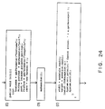
- FIG. 23 An example of a program of a trusted agent described in mobile code is shown in Fig. 23 to Fig. 29.
- This program corresponds to the trusted agent 11 in Fig.1, and is transferred to the client.
- This program includes a function to execute the cryptographic processing of image data.
- This program is for the purpose of reading files in from a WWW (World Wide Web) server and displaying animated images. It is described in Java (an object-oriented language for Internet use developed by Sun Microsystems).
- This program also has a function to read bitmap-format image information (T0 to T9.ppm) in from a server 2,048 bytes (b[]) at a time and perform applet displays.
- This program displays 10 image files one after another and then repeats the action.
- An outline of the display method is as follows. First, a communication path to and from the server is established, and the necessary image files are requested. Next, that communication path is used to receive image files, and images are displayed. Let us now give a more detailed explanation about the program referring to the drawings.
- this invention makes encrypted communication possible by sending an agent that incorporates cryptographic processing units to the communication partner with which encrypted communication is to be carried out, or by receiving an agent that incorporates cryptographic processing units from that partner. For this reason, it is possible to avoid publicizing the encryption method; and, by using agents, the encryption method can be changed at regular or irregular intervals and the parameters needed in encryption can be changed to make it difficult to decipher the encrypted data. Consequently, a strong encryption method is obtained, having a light overhead that is suitable for real time communication.
- This invention is not limited to a cryptosystem but can be widely applied to encode/decode (modulation/demodulation) systems.
- an agent including a program for encode/decode (modulation/demodulation) processing described in mobile code is transmitted prior to data transmission.
Landscapes
- Engineering & Computer Science (AREA)
- Computer Security & Cryptography (AREA)
- Computer Networks & Wireless Communication (AREA)
- Signal Processing (AREA)
- Computer Hardware Design (AREA)
- Computing Systems (AREA)
- General Engineering & Computer Science (AREA)
- Storage Device Security (AREA)
- Computer And Data Communications (AREA)
Abstract
Description
| [number of stages n] | [primitive polynomial] | [period] |
| 2 | x2 + x + 1 | 3 |
| 3 | x3 + x + 1 | 7 |
| 4 | x4 + x + 1 | 15 |
| 5 | x5 + x2 + 1 | 31 |
| 6 | x6 + x + 1 | 63 |
| 7 | x7 + x3 + 1 | 127 |
| 8 | x8 + x4 + x3 + x2 + 1 | 255 |
| 9 | x9 + x4 + 1 | 511 |
| 10 | x10 + x3 + 1 | 1023 |
| 11 | x11 + x2 + 1 | 2047 |
| 12 | x12 + x6 + x4 + x + 1 | 4055 |
Claims (18)
- An encryption communication method for transmitting encrypted data between a first terminal and a second terminal, comprising the steps of:transmitting, from the first terminal in which is installed a first agent including a program for cryptographic processing, a second agent having substantially the same function as the first agent to the second terminal; andperforming an encrypted communication between the first agent and the second agent.
- The encryption communication method according to claim 1, further comprising the step of:changing a parameter needed for the encrypted communication while carrying out synchronization between the first and second agents.
- The encryption communication method according to claim 1 or 2,
wherein the first and second agents can respectively provide a plurality of cryptographic processing units, and further comprising the step of:changing the cryptographic processing units to be used while maintaining synchronisation between the first and second agents. - The encryption communication method according to claim 3,
wherein an encryption method selection server that instructs each of the first and second agents as to which cryptographic processing unit to use is provided, the method further comprising the steps of:instructing as to which cryptographic processing unit is to be used from the encryption method selection server to each of the first and second agents; andchanging at each of the first and second agents the cryptographic processing units to be used in accordance with the instruction received from the encryption method selection server. - The encryption communication method according to claim 3,
wherein each of the first and second agents has a function for determining the cryptographic processing unit to be used, and the functions being the same as one another, the method further comprising the steps of:setting the same initial value in each of the first and second agents;determining a cryptographic processing unit to be used according to the initial value at each of the first and second agents; andchanging cryptographic processing units according to the determination at each of the first and second agents. - The encryption communication method according to any preceding claim,
wherein encryption methods provided by the first and second agents use a pseudo random number. - The encryption communication method according to claim 6, further comprising the steps of:creating a seed of a pseudo random number in the first terminal;setting the created seed in the first and second agents; andgenerating pseudo random numbers in accordance with the set seed and executing cryptographic processing using the pseudo random numbers in the first and second agents respectively.
- The encryption communication method according to claim 7, further comprising the step of:changing the cryptographic processings at regular or irregular intervals.
- The encryption communication method according to claim 6,
wherein a seed server which generates a seed for a pseudo random number is provided, the method further comprising the steps of:generating a seed for a pseudo random number in the seed server;setting the generated seed in the first and second agents; andgenerating a pseudo random number in accordance with the set seed and executing cryptographic processing using the pseudo random number in the first and second agents respectively. - The encryption communication method according to claim 3, 4 or 5,
wherein each of the first and second agents has a function for creating a seed for a pseudo random number, the functions being the same as one another, the method further comprising the steps of:setting the same initial value in each of the first and second agents;creating a seed for a pseudo random number according to the initial value at each of the first and second agents; andgenerating a pseudo random number in accordance with the seed and executing cryptographic processing using the seed in the first and second agents respectively. - An encryption communication method for transmitting encrypted data among a plurality of terminals, comprising the steps of:distributing agents including a program for cryptographic processing from a agent distributing server to the plurality of terminals; andperforming an encrypted communication between the distributed agents.
- The encryption communication method according to claim 11, further comprising the step of:changing a parameter needed for the encrypted communication while carrying out synchronization between the agents.
- The encryption communication method according to claim 11 or 12,
wherein the distributed agents respectively provide a plurality of cryptographic processing units, and wherein the method further comprises:changing the cryptographic processing units to be used while maintaining synchronization between the distributed agents. - An encryption communication method for transmitting encrypted data between a first terminal and a second terminal, comprising the steps of:transmitting an agent including a program for cryptographic processing described in mobile code to the second terminal via a network; andperforming an encryption communication between the first terminal in which a program for cryptographic processing is installed and the second terminal using the agent.
- A storage medium storing a program that provides the following functions when used by a computer:(a) to perform cryptographic processing in a transfer destination terminal,(b) to transmit an agent including a program corresponding to the function (a) to the transfer destination terminal,(c) to perform encrypted communication with the transmitted agent.
- A storage medium storing a program that provides the following functions when used by a computer:(a) to perform cryptographic processing in a transfer destination terminal,(b) to transmit an agent including a program corresponding to the function (a) to a plurality of terminals so as to perform encrypted communication between the plurality of terminals using the agents.
- An encrypted communication system including at least one computer in operable combination with a storage medium according to claim 15 or 16.
- An information processing unit (10) for use in encrypted communication, including:a first agent (14) which is permanently resident in said information processing unit (10) and which includes means for cryptographic processing of information;a second agent (11) which has substantially the same function as the first agent, for use at a destination of said encrypted communication; andtransmitting means (12) for transmitting said second agent (11) to said destination;
whereby, following transmission of said second agent by said transmitting means, said first agent (14) in said information processing unit (10) and said second agent (11) at said destination can perform encrypted communication.
Applications Claiming Priority (3)
| Application Number | Priority Date | Filing Date | Title |
|---|---|---|---|
| JP317505/96 | 1996-11-28 | ||
| JP31750596 | 1996-11-28 | ||
| JP31750596 | 1996-11-28 |
Publications (3)
| Publication Number | Publication Date |
|---|---|
| EP0862301A2 true EP0862301A2 (en) | 1998-09-02 |
| EP0862301A3 EP0862301A3 (en) | 1999-12-29 |
| EP0862301B1 EP0862301B1 (en) | 2004-10-06 |
Family
ID=18088990
Family Applications (1)
| Application Number | Title | Priority Date | Filing Date |
|---|---|---|---|
| EP97305086A Expired - Lifetime EP0862301B1 (en) | 1996-11-28 | 1997-07-10 | An encryption communication system using an agent and a storage medium for storing that agent |
Country Status (3)
| Country | Link |
|---|---|
| US (1) | US6125186A (en) |
| EP (1) | EP0862301B1 (en) |
| DE (1) | DE69731069T2 (en) |
Cited By (18)
| Publication number | Priority date | Publication date | Assignee | Title |
|---|---|---|---|---|
| WO2001047205A3 (en) * | 1999-12-22 | 2002-07-11 | Tashilon Ltd | Enhanced computer network encryption using downloaded software objects |
| FR2825212A1 (en) * | 2001-05-23 | 2002-11-29 | Unlog | SECURE ELECTRONIC COMMUNICATION DEVICE |
| US6853988B1 (en) * | 1999-09-20 | 2005-02-08 | Security First Corporation | Cryptographic server with provisions for interoperability between cryptographic systems |
| US7260724B1 (en) | 1999-09-20 | 2007-08-21 | Security First Corporation | Context sensitive dynamic authentication in a cryptographic system |
| US7391865B2 (en) | 1999-09-20 | 2008-06-24 | Security First Corporation | Secure data parser method and system |
| WO2009127392A1 (en) * | 2008-04-14 | 2009-10-22 | Sia Syncrosoft | Method for processing data in various encoded domains |
| US8009830B2 (en) | 2005-11-18 | 2011-08-30 | Security First Corporation | Secure data parser method and system |
| US8135134B2 (en) | 2007-09-14 | 2012-03-13 | Security First Corp. | Systems and methods for managing cryptographic keys |
| US8155322B2 (en) | 2006-11-07 | 2012-04-10 | Security First Corp. | Systems and methods for distributing and securing data |
| US8266438B2 (en) | 2004-10-25 | 2012-09-11 | Security First Corp. | Secure data parser method and system |
| GB2488753A (en) * | 2011-02-24 | 2012-09-12 | Carlos Eduardo Bevilacqua Leal | Encrypted communication |
| US8473756B2 (en) | 2008-01-07 | 2013-06-25 | Security First Corp. | Systems and methods for securing data using multi-factor or keyed dispersal |
| US8656167B2 (en) | 2008-02-22 | 2014-02-18 | Security First Corp. | Systems and methods for secure workgroup management and communication |
| US8904080B2 (en) | 2006-12-05 | 2014-12-02 | Security First Corp. | Tape backup method |
| US9189777B1 (en) | 1999-09-20 | 2015-11-17 | Security First Corporation | Electronic commerce with cryptographic authentication |
| US9733849B2 (en) | 2014-11-21 | 2017-08-15 | Security First Corp. | Gateway for cloud-based secure storage |
| US9881177B2 (en) | 2013-02-13 | 2018-01-30 | Security First Corp. | Systems and methods for a cryptographic file system layer |
| US10068103B2 (en) | 2010-03-31 | 2018-09-04 | Security First Corp. | Systems and methods for securing data in motion |
Families Citing this family (61)
| Publication number | Priority date | Publication date | Assignee | Title |
|---|---|---|---|---|
| JP4027482B2 (en) * | 1997-12-24 | 2007-12-26 | 富士通株式会社 | Translation apparatus and method for performing cryptographic restoration |
| US6405245B1 (en) | 1998-10-28 | 2002-06-11 | Verticalone Corporation | System and method for automated access to personal information |
| US6871220B1 (en) | 1998-10-28 | 2005-03-22 | Yodlee, Inc. | System and method for distributed storage and retrieval of personal information |
| US8069407B1 (en) | 1998-12-08 | 2011-11-29 | Yodlee.Com, Inc. | Method and apparatus for detecting changes in websites and reporting results to web developers for navigation template repair purposes |
| US7672879B1 (en) | 1998-12-08 | 2010-03-02 | Yodlee.Com, Inc. | Interactive activity interface for managing personal data and performing transactions over a data packet network |
| US7085997B1 (en) | 1998-12-08 | 2006-08-01 | Yodlee.Com | Network-based bookmark management and web-summary system |
| US7000106B2 (en) * | 1999-03-26 | 2006-02-14 | Siemens Communications, Inc. | Methods and apparatus for kernel mode encryption of computer telephony |
| JP2000305453A (en) * | 1999-04-21 | 2000-11-02 | Nec Corp | Ciphering device, deciphering device, and ciphering and deciphering device |
| US7752535B2 (en) | 1999-06-01 | 2010-07-06 | Yodlec.com, Inc. | Categorization of summarized information |
| JP3437498B2 (en) * | 1999-07-22 | 2003-08-18 | パナソニック コミュニケーションズ株式会社 | Image input / output device and status information notification method |
| EP1075108A1 (en) * | 1999-07-23 | 2001-02-07 | BRITISH TELECOMMUNICATIONS public limited company | Cryptographic data distribution |
| JP2001051917A (en) | 1999-08-06 | 2001-02-23 | Matsushita Graphic Communication Systems Inc | Communication equipment and reception reporting method |
| US6823456B1 (en) * | 1999-08-25 | 2004-11-23 | International Business Machines Corporation | System and method for providing trusted services via trusted server agents |
| US7380015B1 (en) * | 1999-09-10 | 2008-05-27 | Kdd Corporation | Apparatus and method for compression-transmitting and decoding picture information and storage medium stored its control programs |
| US20010037450A1 (en) * | 2000-03-02 | 2001-11-01 | Metlitski Evgueny A. | System and method for process protection |
| WO2001067674A2 (en) * | 2000-03-03 | 2001-09-13 | Qualcomm Incorporated | Method and apparatus for participating in group communication services in an existing communication system |
| AU7182701A (en) | 2000-07-06 | 2002-01-21 | David Paul Felsher | Information record infrastructure, system and method |
| US7383329B2 (en) | 2001-02-13 | 2008-06-03 | Aventail, Llc | Distributed cache for state transfer operations |
| US7360075B2 (en) * | 2001-02-12 | 2008-04-15 | Aventail Corporation, A Wholly Owned Subsidiary Of Sonicwall, Inc. | Method and apparatus for providing secure streaming data transmission facilities using unreliable protocols |
| US7353380B2 (en) * | 2001-02-12 | 2008-04-01 | Aventail, Llc, A Subsidiary Of Sonicwall, Inc. | Method and apparatus for providing secure streaming data transmission facilities using unreliable protocols |
| DE10110049A1 (en) * | 2001-03-02 | 2002-09-05 | Bosch Gmbh Robert | Encryption of program data for use in control devices or controllers, involves using decryption key within the control device, to reduce the amount of data to transfer |
| US7181017B1 (en) | 2001-03-23 | 2007-02-20 | David Felsher | System and method for secure three-party communications |
| US20020166051A1 (en) * | 2001-05-03 | 2002-11-07 | Marvin Moser | Method, system, and apparatus for encrypting a web browser script |
| US7210034B2 (en) * | 2003-01-30 | 2007-04-24 | Intel Corporation | Distributed control of integrity measurement using a trusted fixed token |
| US9818136B1 (en) | 2003-02-05 | 2017-11-14 | Steven M. Hoffberg | System and method for determining contingent relevance |
| WO2005008950A1 (en) * | 2003-07-10 | 2005-01-27 | Rsa Security, Inc. | Secure seed generation protocol |
| US7548620B2 (en) * | 2004-02-23 | 2009-06-16 | Verisign, Inc. | Token provisioning |
| US20050235283A1 (en) * | 2004-04-15 | 2005-10-20 | Wilson Christopher S | Automatic setup of parameters in networked devices |
| US20050235063A1 (en) * | 2004-04-15 | 2005-10-20 | Wilson Christopher S | Automatic discovery of a networked device |
| US20050231849A1 (en) * | 2004-04-15 | 2005-10-20 | Viresh Rustagi | Graphical user interface for hard disk drive management in a data storage system |
| US7681007B2 (en) * | 2004-04-15 | 2010-03-16 | Broadcom Corporation | Automatic expansion of hard disk drive capacity in a storage device |
| US20050235364A1 (en) * | 2004-04-15 | 2005-10-20 | Wilson Christopher S | Authentication mechanism permitting access to data stored in a data processing device |
| US20050259458A1 (en) * | 2004-05-21 | 2005-11-24 | Viresh Rustagi | Method and system of encrypting/decrypting data stored in one or more storage devices |
| US8874477B2 (en) | 2005-10-04 | 2014-10-28 | Steven Mark Hoffberg | Multifactorial optimization system and method |
| KR100670832B1 (en) * | 2005-12-12 | 2007-01-19 | 한국전자통신연구원 | Method and device for transmitting and receiving user personal information using agent |
| US20080016248A1 (en) * | 2006-07-14 | 2008-01-17 | George Tsirtsis | Method and apparatus for time synchronization of parameters |
| JP4983165B2 (en) * | 2006-09-05 | 2012-07-25 | ソニー株式会社 | COMMUNICATION SYSTEM AND COMMUNICATION METHOD, INFORMATION PROCESSING DEVICE AND METHOD, DEVICE, PROGRAM, AND RECORDING MEDIUM |
| US7606752B2 (en) | 2006-09-07 | 2009-10-20 | Yodlee Inc. | Host exchange in bill paying services |
| CN101075847A (en) * | 2007-06-25 | 2007-11-21 | 北京创毅视讯科技有限公司 | Method for transmitting synchronizing signal in mobile multi-medium system |
| US8261334B2 (en) | 2008-04-25 | 2012-09-04 | Yodlee Inc. | System for performing web authentication of a user by proxy |
| US8555359B2 (en) | 2009-02-26 | 2013-10-08 | Yodlee, Inc. | System and methods for automatically accessing a web site on behalf of a client |
| CN102428686A (en) | 2009-05-19 | 2012-04-25 | 安全第一公司 | Systems and methods for securely protecting data in the cloud |
| CA2766719C (en) * | 2009-07-31 | 2018-02-13 | International Business Machines Corporation | Collaborative agent encryption and decryption |
| EP2504973B1 (en) | 2009-11-25 | 2016-11-16 | Security First Corp. | Systems and methods for securing data in motion |
| CA2800809A1 (en) | 2010-05-28 | 2011-12-01 | Lawrence A. Laurich | Accelerator system for use with secure data storage |
| US8718278B2 (en) * | 2011-01-20 | 2014-05-06 | International Business Machines Corporation | Method and system for encryption of a datastream |
| US8700991B1 (en) * | 2011-07-19 | 2014-04-15 | Amazon Technologies, Inc. | Protecting content presented in a web browser |
| US20140237239A1 (en) * | 2012-12-31 | 2014-08-21 | Safelylocked, Llc | Techniques for validating cryptographic applications |
| JP2014192612A (en) * | 2013-03-26 | 2014-10-06 | Toshiba Corp | Generation apparatus, encryption device, decoder, decoding method and program |
| WO2015142765A1 (en) | 2014-03-17 | 2015-09-24 | Coinbase, Inc | Bitcoin host computer system |
| SE538279C2 (en) | 2014-09-23 | 2016-04-19 | Kelisec Ab | Procedure and system for determining the presence of |
| SE539271C2 (en) | 2014-10-09 | 2017-06-07 | Kelisec Ab | Mutual authentication |
| SE538304C2 (en) * | 2014-10-09 | 2016-05-03 | Kelisec Ab | Improved installation of a terminal in a secure system |
| SE542460C2 (en) | 2014-10-09 | 2020-05-12 | Kelisec Ab | Improved security through authenticaton tokens |
| SE540133C2 (en) | 2014-10-09 | 2018-04-10 | Kelisec Ab | Improved system for establishing a secure communication channel |
| US9735958B2 (en) * | 2015-05-19 | 2017-08-15 | Coinbase, Inc. | Key ceremony of a security system forming part of a host computer for cryptographic transactions |
| US10341087B2 (en) * | 2016-12-29 | 2019-07-02 | Intel Corporation | Techniques for cipher system conversion |
| SG11202010090RA (en) | 2018-04-17 | 2020-11-27 | Coinbase Inc | Offline storage system and method of use |
| US11394543B2 (en) | 2018-12-13 | 2022-07-19 | Coinbase, Inc. | System and method for secure sensitive data storage and recovery |
| EP4007983A4 (en) | 2019-08-01 | 2023-08-30 | Coinbase, Inc. | SYSTEMS AND METHODS FOR GENERATION OF SIGNATURES |
| US11943350B2 (en) * | 2019-10-16 | 2024-03-26 | Coinbase, Inc. | Systems and methods for re-using cold storage keys |
Family Cites Families (8)
| Publication number | Priority date | Publication date | Assignee | Title |
|---|---|---|---|---|
| DE3003998A1 (en) * | 1980-02-04 | 1981-09-24 | Licentia Patent-Verwaltungs-Gmbh, 6000 Frankfurt | DATA ENCRYPTION AND DECRYLING SYSTEM |
| US4885778A (en) * | 1984-11-30 | 1989-12-05 | Weiss Kenneth P | Method and apparatus for synchronizing generation of separate, free running, time dependent equipment |
| US4677670A (en) * | 1985-07-01 | 1987-06-30 | Henderson Jr Paul B | Paired-secure message identification controller for computers and the like |
| JPS63278438A (en) * | 1987-05-11 | 1988-11-16 | Hitachi Ltd | Cryptographic system by secret cryptograph procedure |
| JPH0294836A (en) * | 1988-09-30 | 1990-04-05 | Aisin Seiki Co Ltd | Privacy telephone communication controller |
| JP2821306B2 (en) * | 1992-03-06 | 1998-11-05 | 三菱電機株式会社 | Authentication method and system between IC card and terminal |
| US5349643A (en) * | 1993-05-10 | 1994-09-20 | International Business Machines Corporation | System and method for secure initial program load for diskless workstations |
| US6075863A (en) * | 1996-02-28 | 2000-06-13 | Encanto Networks | Intelligent communication device |
-
1997
- 1997-07-08 US US08/893,546 patent/US6125186A/en not_active Expired - Lifetime
- 1997-07-10 EP EP97305086A patent/EP0862301B1/en not_active Expired - Lifetime
- 1997-07-10 DE DE69731069T patent/DE69731069T2/en not_active Expired - Lifetime
Cited By (36)
| Publication number | Priority date | Publication date | Assignee | Title |
|---|---|---|---|---|
| US8726033B2 (en) | 1999-09-20 | 2014-05-13 | Security First Corporation | Context sensitive dynamic authentication in a cryptographic system |
| US6853988B1 (en) * | 1999-09-20 | 2005-02-08 | Security First Corporation | Cryptographic server with provisions for interoperability between cryptographic systems |
| US7260724B1 (en) | 1999-09-20 | 2007-08-21 | Security First Corporation | Context sensitive dynamic authentication in a cryptographic system |
| US7391865B2 (en) | 1999-09-20 | 2008-06-24 | Security First Corporation | Secure data parser method and system |
| US9613220B2 (en) | 1999-09-20 | 2017-04-04 | Security First Corp. | Secure data parser method and system |
| US7802104B2 (en) | 1999-09-20 | 2010-09-21 | Security First Corporation | Context sensitive dynamic authentication in a cryptographic system |
| US9449180B2 (en) | 1999-09-20 | 2016-09-20 | Security First Corp. | Secure data parser method and system |
| US9189777B1 (en) | 1999-09-20 | 2015-11-17 | Security First Corporation | Electronic commerce with cryptographic authentication |
| US8214650B2 (en) | 1999-09-20 | 2012-07-03 | Security First Corporation | Context sensitive dynamic authentication in a cryptographic system |
| WO2001047205A3 (en) * | 1999-12-22 | 2002-07-11 | Tashilon Ltd | Enhanced computer network encryption using downloaded software objects |
| FR2825212A1 (en) * | 2001-05-23 | 2002-11-29 | Unlog | SECURE ELECTRONIC COMMUNICATION DEVICE |
| WO2002096061A3 (en) * | 2001-05-23 | 2003-03-13 | Anonymex | Secure electronic communication device |
| US8266438B2 (en) | 2004-10-25 | 2012-09-11 | Security First Corp. | Secure data parser method and system |
| US9992170B2 (en) | 2004-10-25 | 2018-06-05 | Security First Corp. | Secure data parser method and system |
| US9906500B2 (en) | 2004-10-25 | 2018-02-27 | Security First Corp. | Secure data parser method and system |
| US9985932B2 (en) | 2004-10-25 | 2018-05-29 | Security First Corp. | Secure data parser method and system |
| US9935923B2 (en) | 2004-10-25 | 2018-04-03 | Security First Corp. | Secure data parser method and system |
| US9871770B2 (en) | 2004-10-25 | 2018-01-16 | Security First Corp. | Secure data parser method and system |
| US11178116B2 (en) | 2004-10-25 | 2021-11-16 | Security First Corp. | Secure data parser method and system |
| US8009830B2 (en) | 2005-11-18 | 2011-08-30 | Security First Corporation | Secure data parser method and system |
| US8320560B2 (en) | 2005-11-18 | 2012-11-27 | Security First Corporation | Secure data parser method and system |
| US8155322B2 (en) | 2006-11-07 | 2012-04-10 | Security First Corp. | Systems and methods for distributing and securing data |
| US8787583B2 (en) | 2006-11-07 | 2014-07-22 | Security First Corp. | Systems and methods for distributing and securing data |
| US9774449B2 (en) | 2006-11-07 | 2017-09-26 | Security First Corp. | Systems and methods for distributing and securing data |
| US9195839B2 (en) | 2006-12-05 | 2015-11-24 | Security First Corp. | Tape backup method |
| US8904080B2 (en) | 2006-12-05 | 2014-12-02 | Security First Corp. | Tape backup method |
| US8135134B2 (en) | 2007-09-14 | 2012-03-13 | Security First Corp. | Systems and methods for managing cryptographic keys |
| US8473756B2 (en) | 2008-01-07 | 2013-06-25 | Security First Corp. | Systems and methods for securing data using multi-factor or keyed dispersal |
| US8656167B2 (en) | 2008-02-22 | 2014-02-18 | Security First Corp. | Systems and methods for secure workgroup management and communication |
| WO2009127392A1 (en) * | 2008-04-14 | 2009-10-22 | Sia Syncrosoft | Method for processing data in various encoded domains |
| US10068103B2 (en) | 2010-03-31 | 2018-09-04 | Security First Corp. | Systems and methods for securing data in motion |
| GB2488753A (en) * | 2011-02-24 | 2012-09-12 | Carlos Eduardo Bevilacqua Leal | Encrypted communication |
| US9881177B2 (en) | 2013-02-13 | 2018-01-30 | Security First Corp. | Systems and methods for a cryptographic file system layer |
| US10402582B2 (en) | 2013-02-13 | 2019-09-03 | Security First Corp. | Systems and methods for a cryptographic file system layer |
| US9733849B2 (en) | 2014-11-21 | 2017-08-15 | Security First Corp. | Gateway for cloud-based secure storage |
| US10031679B2 (en) | 2014-11-21 | 2018-07-24 | Security First Corp. | Gateway for cloud-based secure storage |
Also Published As
| Publication number | Publication date |
|---|---|
| DE69731069T2 (en) | 2005-02-17 |
| DE69731069D1 (en) | 2004-11-11 |
| EP0862301B1 (en) | 2004-10-06 |
| US6125186A (en) | 2000-09-26 |
| EP0862301A3 (en) | 1999-12-29 |
Similar Documents
| Publication | Publication Date | Title |
|---|---|---|
| EP0862301B1 (en) | An encryption communication system using an agent and a storage medium for storing that agent | |
| EP0702477B1 (en) | System for signatureless transmission and reception of data packets between computer networks | |
| US7177424B1 (en) | Cryptographic apparatus and method | |
| US20050226408A1 (en) | Apparatus and method for encryption and decryption | |
| US20090103726A1 (en) | Dual-mode variable key length cryptography system | |
| US6891952B1 (en) | Dynamic key generation and confidential synchronization of encryption components | |
| EP1049287A2 (en) | Encryption/decryption method and authentication method using multi-affine key system and apparatuses using the same | |
| EP1133099A2 (en) | Method and apparatus for symmetric-key encryption | |
| CN114448730B (en) | Packet forwarding method and device based on block chain network and transaction processing method | |
| US10142119B2 (en) | Communication method and apparatus using changing destination and return destination ID's | |
| JP2000138668A (en) | An encryption system for packet switching networks based on digital chaos model | |
| AU1570499A (en) | Data communications | |
| KR940017394A (en) | Encryption key management device and method | |
| EA010611B1 (en) | Method and apparatus for cryptographically processing data | |
| JPH1155243A (en) | Method and apparatus for implementing a pair key in a key management scheme, achieving perfect secret transfer in a closed user group, and transmitting datagram multicast | |
| JP2004501529A (en) | Method and system for uniquely associating multicasted content with each of a plurality of recipients | |
| CN211791776U (en) | Distributed recording and broadcasting system | |
| WO2000018078A1 (en) | Secure message exchange method using intermediaries | |
| CN120281477A (en) | Quantum key distribution method and system after satellite communication based on QUIC | |
| JP3172396B2 (en) | Cryptographic communication device and cryptographic communication system | |
| JP2000092044A (en) | Communications system | |
| JPH10215243A (en) | Encrypted communication method using agent and mobile code storage medium | |
| US20030191965A1 (en) | Method and apparatus to facilitate virtual transport layer security on a virtual network | |
| JP3202544B2 (en) | Encryption communication device and encryption device | |
| JP2003338812A (en) | Encryption system |
Legal Events
| Date | Code | Title | Description |
|---|---|---|---|
| PUAI | Public reference made under article 153(3) epc to a published international application that has entered the european phase |
Free format text: ORIGINAL CODE: 0009012 |
|
| AK | Designated contracting states |
Kind code of ref document: A2 Designated state(s): DE FR GB |
|
| AX | Request for extension of the european patent |
Free format text: AL;LT;LV;RO;SI |
|
| PUAL | Search report despatched |
Free format text: ORIGINAL CODE: 0009013 |
|
| AK | Designated contracting states |
Kind code of ref document: A3 Designated state(s): AT BE CH DE DK ES FI FR GB GR IE IT LI LU MC NL PT SE |
|
| AX | Request for extension of the european patent |
Free format text: AL;LT;LV;RO;SI |
|
| RIC1 | Information provided on ipc code assigned before grant |
Free format text: 6H 04L 29/06 A, 6G 06F 9/445 B |
|
| 17P | Request for examination filed |
Effective date: 20000207 |
|
| AKX | Designation fees paid |
Free format text: DE FR GB |
|
| 17Q | First examination report despatched |
Effective date: 20010809 |
|
| GRAP | Despatch of communication of intention to grant a patent |
Free format text: ORIGINAL CODE: EPIDOSNIGR1 |
|
| GRAS | Grant fee paid |
Free format text: ORIGINAL CODE: EPIDOSNIGR3 |
|
| GRAA | (expected) grant |
Free format text: ORIGINAL CODE: 0009210 |
|
| AK | Designated contracting states |
Kind code of ref document: B1 Designated state(s): DE FR GB |
|
| REG | Reference to a national code |
Ref country code: GB Ref legal event code: FG4D |
|
| REF | Corresponds to: |
Ref document number: 69731069 Country of ref document: DE Date of ref document: 20041111 Kind code of ref document: P |
|
| PLBE | No opposition filed within time limit |
Free format text: ORIGINAL CODE: 0009261 |
|
| STAA | Information on the status of an ep patent application or granted ep patent |
Free format text: STATUS: NO OPPOSITION FILED WITHIN TIME LIMIT |
|
| ET | Fr: translation filed | ||
| 26N | No opposition filed |
Effective date: 20050707 |
|
| REG | Reference to a national code |
Ref country code: FR Ref legal event code: PLFP Year of fee payment: 19 |
|
| PGFP | Annual fee paid to national office [announced via postgrant information from national office to epo] |
Ref country code: DE Payment date: 20150707 Year of fee payment: 19 Ref country code: GB Payment date: 20150708 Year of fee payment: 19 |
|
| PGFP | Annual fee paid to national office [announced via postgrant information from national office to epo] |
Ref country code: FR Payment date: 20150629 Year of fee payment: 19 |
|
| REG | Reference to a national code |
Ref country code: DE Ref legal event code: R119 Ref document number: 69731069 Country of ref document: DE |
|
| GBPC | Gb: european patent ceased through non-payment of renewal fee |
Effective date: 20160710 |
|
| PG25 | Lapsed in a contracting state [announced via postgrant information from national office to epo] |
Ref country code: FR Free format text: LAPSE BECAUSE OF NON-PAYMENT OF DUE FEES Effective date: 20160801 Ref country code: DE Free format text: LAPSE BECAUSE OF NON-PAYMENT OF DUE FEES Effective date: 20170201 |
|
| REG | Reference to a national code |
Ref country code: FR Ref legal event code: ST Effective date: 20170331 |
|
| PG25 | Lapsed in a contracting state [announced via postgrant information from national office to epo] |
Ref country code: GB Free format text: LAPSE BECAUSE OF NON-PAYMENT OF DUE FEES Effective date: 20160710 |