EP0862141A2 - Bilddarstellungsverfahren und Vorrichtung zur Durchführung des Verfahrens - Google Patents
Bilddarstellungsverfahren und Vorrichtung zur Durchführung des Verfahrens Download PDFInfo
- Publication number
- EP0862141A2 EP0862141A2 EP98250057A EP98250057A EP0862141A2 EP 0862141 A2 EP0862141 A2 EP 0862141A2 EP 98250057 A EP98250057 A EP 98250057A EP 98250057 A EP98250057 A EP 98250057A EP 0862141 A2 EP0862141 A2 EP 0862141A2
- Authority
- EP
- European Patent Office
- Prior art keywords
- memory matrix
- spatial position
- image information
- memory
- representing
- Prior art date
- Legal status (The legal status is an assumption and is not a legal conclusion. Google has not performed a legal analysis and makes no representation as to the accuracy of the status listed.)
- Withdrawn
Links
Images


Classifications
-
- G—PHYSICS
- G06—COMPUTING OR CALCULATING; COUNTING
- G06T—IMAGE DATA PROCESSING OR GENERATION, IN GENERAL
- G06T15/00—Three-dimensional [3D] image rendering
- G06T15/50—Lighting effects
- G06T15/55—Radiosity
Definitions
- the invention relates to an image display method for Representation of computer-modeled objects according to the The preamble of claim 1 and a device for Implementation of the method according to the preamble of the claim 9.
- objects are usually simulated using grid models, the objects being defined by the spatial coordinates of the nodes of the grid model and by the optical properties, such as color and reflection behavior, of the polygon surfaces lying between the nodes.
- Such computer graphics systems are for example from VOORHIES, D .; FORAN, J .: Reflection Vector Shading Hardware, SIGGRAPH '94 and JACK ⁇ L, D .; Radoreler, H .: A Real Time Rendering System with Normal Vector Shading; 9 th Euro Graphics Workshop on Graphics Hardware, Oslo (Norway), 1994 known.
- the individual polygon surfaces are divided into raster elements (English pixels), the position and the spatial position of the local surface normal being calculated for each raster element, which is therefore decisive for the reflection behavior of the image impression.
- An inclination of the local surface normal within the polygon surface makes it possible, on the one hand, to simulate curved polygon surfaces, so that a kink-free and thus optically unobtrusive transition can be achieved at the edges between adjacent polygon surfaces.
- the image impression is then calculated individually for each raster element in accordance with a local lighting model, the viewer's perspective, the spatial position and the optical properties of the raster element, the orientation of the local surface normal and the spatial position and the optical properties of the light sources that illuminate the objects are taken into account.
- a disadvantage of the known image display methods is that the image impression a raster element essentially only from the spatial position of the raster element relative to the individual Light sources and the optical properties of the grid element and depends on the light sources. Interactions between the individual raster elements or objects spatial scene are only taken into account by that mutual shadowing is determined and the shadowed Raster elements are suppressed in the display (English hidden surface removal). The one with the known ones Images generated by image display methods therefore appear because of the largely isolated calculation of the individual Artificial grid elements independently of each other.
- the invention is therefore based on the object of an image display method for the representation of computer-modeled To create objects in which the individual objects not isolated, but as part of a spatial Scene with corresponding optical interactions taken into account to get the most natural possible picture impression to obtain.
- the task is based on an image rendering process according to the preamble of claim 1, by the characteristic features of claim 1 or - with respect the device for carrying out the method - solved by the features of claim 9.
- the invention includes the technical teaching that Image impression for each raster element not only accordingly to calculate the local lighting model, but also Reflections of the environment should be taken into account by depending on the spatial position of the local surface normal a memory matrix is addressed and a corresponding one Image information value is read out, the environmental impression from a certain perspective.
- local lighting model is here and in not following the above and preferably limited Phong lighting model used, but basically also includes other lighting models, which is the calculation of the image impression of a raster element a polygon surface depending on the lighting conditions and enable the geometric relationships.
- the inventive measures can be both pure software measures as well as by means of suitable special Run hardware.
- the hardware solution has the advantage that in particular by parallel arranged assemblies (English pipelines) executed simultaneously Operations can save a lot of time.
- the individual Polygon surfaces preferably in several parallel Equidistant raster lines (English scanlines) divided into which then in turn arranged the grid elements equidistantly will.
- the polygon area is divided by the first assembly or functional group of a computing unit, the one at their entrance the spatial position of the polygon area representing the first parameter set and a large number of first coordinate sets at its output outputs the spatial position of a grid element represent.
- the calculation of the first parameter set for each polygon surface can be replaced by a parent Graphics system done that several of the described here Computing units can include, so that it is possible to Image impression of several objects in a spatial scene in parallel to calculate, reducing computing time for complex scenes is drastically reduced.
- the computing unit also has a second module that have one for each raster element of the polygon surface second coordinate set that calculates the spatial location represents the local surface normal.
- the local surface normal does not match the surface normal the entire polygon area must match, since the polygon surface is preferably curved to the Edges of contiguous polygon surfaces a kink-free, to achieve optically unobtrusive transition.
- the surface normals at the corner points of the individual polygon surfaces given by the first set of parameters, the spatial Position of the polygon area represented.
- the calculation the local surface normal for the individual grid elements the polygon surface is then made by interpolating the vertex normals, which also has the advantage that the local Surface normals of neighboring polygon areas on the common Cornerstones are the same and are along the common Edge slightly due to interpolation distinguish what is essentially a kink free and thus optically inconspicuous transition between neighboring ones Polygon surfaces leads.
- a third assembly is provided, the for each grid element according to the local lighting model calculates a first image information value.
- the third module takes one on the input side second parameter set on the spatial location and the optical properties of at least a first light source represents.
- the second parameter set preferably contains for each light source, its spatial coordinates, the vector components the main emission direction, the ambience, diffuse and specular color of the light source and, if applicable a so-called spotlight cutoff angle that the Opening angle of the radiation cone indicates outside of it a viewer no longer perceives the light source.
- the third module is on the input side with the first assembly connected to the first coordinate set to record, which represents the spatial position of the raster element.
- To record the second set of coordinates, which represents the orientation of the local surface normal is the third module on the input side with the second module connected.
- the computing unit also has a fourth module on for each grid element depending on the Perspective of the virtual viewer the position of the grid element calculated on a screen.
- the fourth For this purpose, the module is on the input side with the first module connected and calculated from the first coordinate sets, which the spatial location of the individual grid elements represent, each a two-dimensional screen data set, which represents the horizontal and vertical position at which the respective grid element within of the screen coordinate system must appear to be the one you want Generating perspective.
- each calculated an image information value which at a use of the known RGB color model, for example reflects the intensity of the three primary colors.
- image information value is not based on reproduction of the three primary colors according to the RGB color model limited, but includes when using others Color models, such as the CMYK color model or the HSB color model, including the reproduction of the corresponding Parameter.
- it is a monochrome Representation also possible as image information value only the gray tint of the respective raster element to calculate.
- the only decisive factor here is that the Image information value the image impression of the respective raster element reproduces and a corresponding control of a Screen for playback.
- a first memory matrix is provided, which in each Memory location contains a second image information value, which gives the picture impression of the environment from a certain Contains perspective.
- the addressing is done by a Address value that depends on a first computing unit from which the spatial position of the local surface normal reproducing second coordinate set and / or the reflecting the position of the virtual viewer third parameter set is calculated.
- the second image information value from the memory matrix read out which reflects reflections of the surroundings and from a second arithmetic unit with the first image information value mixed, which corresponds to the local lighting model was calculated so that the user the opportunity has to determine by specifying weighting factors to what extent the reflections of the environment are taken into account will.
- the weighting of the surrounding reflections is preferably coupled to the reflectance, the material property for the respective polygon surface is specified. So environmental reflections are on a blunt surface, for example a piece of chalk hardly recognizable while a mirrored surface the environment reflects very well.
- the storage matrix preferably forms a cubic one Environment cube according to, in whose The center point of each grid element lies, each Area element of the envelope surface is a storage location of the storage matrix is assigned, the content of which is the image impression the surroundings in the respective direction.
- the cubic Envelope surface is thus an all-round shot of the Environment from the perspective of the individual grid elements represents.
- the viewer takes the area of the surroundings from the grid element true that is intersected by the reflected eye vector.
- the first arithmetic unit used to calculate the address value calculates the position of the virtual Third parameter set and the one reflecting the spatial position of the respective raster element first coordinate set, first the eye vector, the connection line between the viewer and the respective raster element, which is also referred to as a visual ray becomes. Then the eye vector and the spatial position of the local surface normal second coordinate set the reflected eye vector is calculated and the intersection of the reflected eye vector with of the cubic envelope surface. The viewer sees then the area of the cubic envelope that is reflected by the Eye vector is cut.
- the second arithmetic unit calculated from the reflected eye vector the address value for the memory location of the memory matrix, the the image information value for the associated surface element contains the cubic envelope.
- the invention is not based on exclusive consideration specular reflection on the respective raster element limited. Rather, it is possible instead or additionally diffuse reflections of the environment consider.
- the memory matrix is addressed depending on which the spatial location the local surface normal representing second coordinate set, because the viewer's position at the diffuse Reflection has no influence on the image impression.
- the default The environmental impression can be used for specular and diffuse reflection takes place through the same memory matrix, however, it is to achieve special optical effects also possible different environments for specular and to provide diffuse reflection in different Storage matrices or in different storage areas same memory matrix are stored.
- the environmental reflections are calculated for the diffuse reflection as a function of the local surface normal and dependent for specular reflection from the position of the virtual viewer on the one hand and the local surface normal on the other hand.
- Variant of the invention is also provided also the position of the respective grid element or of the entire polygon area.
- This selection value is then used for position-dependent Selection of the first or second memory matrix from a variety of storage matrices, each different Play environments. Instead, it is also possible the selection value for addressing the first or second memory matrix and within the memory matrix a memory area depending on the position to select. In this way it is possible within different environments to the spatial scene take into account what leads to a more natural picture impression leads than when considering one for all grid elements unified global environment.
- the storage matrices form - as already explained above - usually a cubic envelope around each Grid element and define an all-round image from the perspective of the respective grid element or the respective polygon area, each memory location of the Storage matrix clearly a solid angle area of the environment assigned.
- each memory location of the Storage matrix clearly a solid angle area of the environment assigned.
- only define the storage matrices a part - hereinafter also referred to as a sample - the Environment that is repeated on the cubic envelope.
- simulating a cloudy sky as an environment for example, it is not necessary to heaven to define from all possible directions. It rather, one or two clouds against a blue background is sufficient to define and this pattern on the cubic Repeat envelope surface.
- the storage matrix could then for example a quarter of one side of the cubic envelope define so that the given pattern on the cubic envelope surface appears a total of 24 times.
- the optical resolution of the environmental representation can be advantageous increase since each storage space remains the same Size of the memory matrix a smaller solid angle range is assigned to the environment.
- no increase is made optical resolution of the surroundings is required, so the environment can be kept the same optical Resolution advantageous with a smaller memory matrix represent.
- the addressing the memory matrix must be different from that of the Variants of the invention described above, in which the Storage matrix each a complete all-round picture of the Environment defined. First, the addressing verifier calculated that with diffuse reflection of the local surface normal and with specular reflection the reflected Eye vector corresponds.
- the invention is therefore for addressing the memory matrix an additional coordinate transformation is required by the coordinates of the intersection of the addressing vector Area element on the cubic envelope in the coordinates within the given pattern.
- the predefined patterns are calculated such that the abutting edges are adjacent Pattern on the cubic envelope despite the Repetition of the pattern are not visible. This sets ahead that between adjacent patterns along the butt edges there are no jumps in intensity or color. For It is about avoiding the so-called mach band effect also advantageous to calculate the pattern such that the Change the intensity or color values between neighboring ones Patterns across the butt edge is constant.
- the patterns in practice often from existing picture templates and the requirements described above therefore mostly can not meet a corresponding Correction of the intensity or color values too after reading in the template. That's the way it is for example possible, a template in paper form digitize and into the memory matrix read in.
- the digitized pattern processed by means of an image processing unit to the Optical disturbances at the abutting edges described above to prevent.
- This processing of the imported Pattern is preferably done by a separate image processing unit, which is connected to the memory matrix and the image information values in the individual storage locations in the vicinity of the abutting edges.
- a further memory matrix is provided for this purpose, where each raster element of the respective polygon area assigned to a memory location of this memory matrix is. This memory matrix is addressed by an addressing unit, from which the spatial location the first parameter set and the polygon area the one reflecting the spatial position of the respective raster element calculates an address value in the first coordinate set, of the spatial location of the grid element within the polygon area.
- the Address value does not depend on the spatial position of the polygon area depends as a whole, but solely by the location of the raster element within the polygon area because the surface structure would otherwise occur during a movement of the object would "wander" on the object surface.
- third storage matrix then becomes an image information value read out the surface structure of the polygon surface reproduces in the respective grid element.
- the calculation the image information value used to control the screen is then carried out by the second computing unit in Dependence on the read surface structure value.
- the body or area shown on the screen should be - as already described above - reproduced in the computer as a grid model.
- the surface therefore consists of numerous polygon surfaces whose spatial position through the spatial coordinates of the nodes of the grid model is defined.
- polygon surfaces Triangles used. This means that in the grid model three points connected by edges are.
- the use of triangles to model the Surfaces has the advantage that the surface normal is one Triangle unambiguously by the spatial coordinates of the corner points is defined because three points always lie in one plane, while with polygons with more than three vertices the possibility there is that the corner points are not exactly in one Level lie, so that the surface normal is not exact is defined.
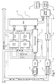
- Figure 1 shows a computing unit 1, which is a representation made possible by computer-modeled objects and part of them of a comprehensive computer graphics system from which only one system bus 2 is shown here.
- the single ones Objects are here in the graphics system as a grid model saved and by the spatial coordinates of the nodes of the lattice model and the optical properties the triangular between the nodes Polygon surfaces - for example the color and the reflection properties - Are defined.
- the illustrated computing unit 1 successively calculates the image impression of all the polygon areas of the individual objects, the spatial position of the respective polygon area, the desired perspective and the lighting situation being specified by the graphics system via the system bus 2. For this purpose, the computing unit 1 receives a parameter set from the graphics system via the system bus 2 for each polygon area to be displayed, which sets out the spatial position and the optical properties of the respective polygon area and enables fine division of the polygon area into a plurality of raster elements, which are each arranged in raster lines.
- the parameter set contains the spatial coordinates (x S , y S , z S ) of a corner point P start of the triangle, the edge increments ⁇ lu, ⁇ ru, ⁇ ld, ⁇ rd, the number of raster lines n 1 , n 2 of the triangle, and the inclination ⁇ zx of Triangular area to the X axis and the inclination ⁇ zy of the triangular area to the Y axis.
- the parameter set contains the coordinates of the local surface normal N Start in the given corner point as well as the vector increments ⁇ N x , ⁇ N y , which enable the local surface normal to be calculated in each raster element of the triangular surface.
- the triangular surface is therefore not necessarily flat, but is usually curved. On the one hand, this enables the curvature to be adapted to a predetermined surface course of the objects. On the other hand, it is possible in this way to achieve a kink-free and thus optically unobtrusive transition at the edges between adjacent triangle surfaces.
- the parameter set also contains information about the color of the triangular surface, the absorption behavior, the transparency of the triangular surface and the like.
- the parameter set supplied by the higher-level graphics system is fed in the computing unit 1 to, among other things, a module 3 (English scanline initializer) which first divides the triangular area into a plurality of raster lines and for each raster line the spatial coordinates of the starting point (x l , y l , z l ) and the end point (x r , y r , z r ) are calculated.
- FIGS. 2a and 2b show such a triangular area to illustrate the division into grid elements.
- the individual raster lines are each parallel to the X axis and equidistant from each other, so that the Y coordinate of all raster elements of a raster line results from the Y coordinate y S of the predetermined corner point P Start and the number i of the raster line.
- the X coordinate x l of the starting point of each raster line results from the X coordinate x S of the specified starting point P start , the number i of the raster line and the edge increment ⁇ lu or ⁇ ld. Within the first n 1 raster lines, the edge increment ⁇ lu and then the edge increment ⁇ ld are used.
- x l x S + ⁇ lu . i
- x l x S + ⁇ lu . n 1 + (in 1 ) .
- ⁇ ld For n 1 ⁇ i ⁇ n 1 + n 2nd
- the X coordinate x r of the end point of each raster line results from the X coordinate x S of the start point P start , the number i of the raster line and the edge increment ⁇ ru or ⁇ rd.
- the assembly 4 thus calculates the for each raster element Polygon area the coordinates, what a requirement for one later calculation of the image impression according to a local one Lighting model is.
- the parameter set supplied by the higher-level graphics system which reproduces the spatial position of a triangle in each case, is also fed to a further assembly 5 (normal vector initializer), which contains the components (xn l , yn l , zn l ) of the normal vector N l calculated at the starting point of each raster line.
- normal vector initializer contains the components (xn l , yn l , zn l ) of the normal vector N l calculated at the starting point of each raster line.
- the vector increment ⁇ N y here reflects the change in the normal vector during the transition to the next raster line, while the vector increment ⁇ N x determines the change in the normal vector between two raster elements of a raster line.
- the coordinates of a raster element calculated by the assembly 4 and the components of the normal vector at the location of the respective raster element determined by the assembly 6 are then fed to a further assembly 7, which calculates the image impression of the respective raster element in accordance with a local lighting model.
- the assembly 7 requires information about the lighting situation and the desired perspective.
- the higher-level graphics system supplies a parameter set ex , ey , ez via the system bus, which determines the position of a virtual viewer and thus the perspective.
- the module 7 receives a parameter set for each light source, which represents the position lx , ly, lz, the main emission direction and the intensity of the light source.
- the computing unit 1 shown therefore additionally calculates the reflections of the environment on the respective object surface, being diffuse reflection and specular reflection can be taken into account independently of one another.
- the computing unit 1 has two memory elements 8, 9 a variety of storage spaces, each storage space of the memory elements 8, 9 an image information value contains the image impression of the surroundings from a certain perspective.
- the storage elements 8, 9 form - as shown in Figure 4a and 4b - each cubic envelope surfaces according to the respective grid element surrounded, each storage space of the storage element 8, 9 assigned to a surface element of the envelope surface is and the image impression of the environment in the respective Direction defined. So the cubic envelopes are quasi all - round pictures of the surroundings from the perspective of individual grid elements.
- Each storage element 8, 9 forms a plurality of cubic envelopes according to order within the spatial Different ambient reflections depending on the position to be able to take into account.
- the different environments are different in the two memory elements 8, 9 Storage areas defined.
- the storage areas are selected by a Addressing unit 10, 11, the input side with the Module 4 is connected to record the parameter set, the spatial position of the respective raster element reproduces.
- the addressing units 10, 11 determine then depending on the position of the grid element, which environment to consider and choose the appropriate one Memory area in the memory elements 8, 9.
- the addressing units 10, 11 have the Task, within the memory areas selected depending on the position to address the memory locations that the Represent the image impression of the surroundings reflected on the object.
- the raster element addresses are dependent from the position of the virtual viewer on the one hand and the spatial position of the local surface normal on the other hand.
- the addressing unit 10 therefore calculates the position of the viewer and the position of each Raster elements first - as shown in Figure 4b - the eye vector E, i.e. the connecting line between the virtual viewer and the grid element. Subsequently then becomes the eye vector E and the local surface normal N the reflected eye vector M is calculated and the Intersection of the reflected eye vector M with the cubic one Envelope area determined. Then addresses the Addressing unit 10 the associated storage space Storage element 8 and reads the associated image information value out.
- the computing unit 1 calculates the image information values of the individual raster elements on the one hand according to the Phong's lighting model and determined on the other the image impression resulting from diffuse and specular reflection the environment on the respective raster element.
- the resulting three image information values are then fed to a further computing unit 12, which accordingly predetermined weighting factors the final Image information value calculated.
- the screen coordinate set is then used for addressing a screen memory 15 which stores the image information values of the individual raster elements from module 7.
- the screen memory 15 contains a perspective Image of the virtual spatial scene.
- This image is then made by using an input the display driver circuit connected to the display memory 15 16 and the screen 13.
- the invention is not limited in its execution the preferred embodiments given above. Rather, a number of variants are conceivable, which fundamentally different from the solution shown makes use of any type.
Landscapes
- Engineering & Computer Science (AREA)
- Computer Graphics (AREA)
- Physics & Mathematics (AREA)
- General Physics & Mathematics (AREA)
- Theoretical Computer Science (AREA)
- Image Generation (AREA)
Abstract
Description
- Figur 1
- als bevorzugtes Ausführungsbeispiel der Erfindung eine Recheneinheit zur Darstellung von computermodellierten Objekten als Bestandteil eines umfassenden Computer-Grafiksystems,
- Figur 2a, 2b
- exemplarisch eine Polygonfläche eines computermodellierten Objekts zur Veranschaulichung der Aufteilung der Polygonfläche in Rasterzeilen und Rasterelemente,
- Figur 3
- eine schematische Darstellung der Beleuchtungssituation eines Rasterelements zur Veranschaulichung des lokalen Beleuchtungsmodells sowie
- Figur 4a, 4b
- jeweils eine kubische Hüllfläche um ein Rasterelement zur Veranschaulichung der Berechnung von Umgebungsreflexionen bei diffuser bzw. spekularer Reflexion.

- acm, dcm, scm
- ambiente, diffuse bzw. spekulare Farbe des Materials
- ecm
- emissive Farbe des Materials
- srm
- spekularer Exponent des Materials
- acli , dcli , scli
- ambiente, diffuse bzw. spekulare Farbe von Lichtquelle i
- Ppli
- Position von Lichtquelle i
- sdli
- Hauptabstrahlrichtung von Lichtquelle i
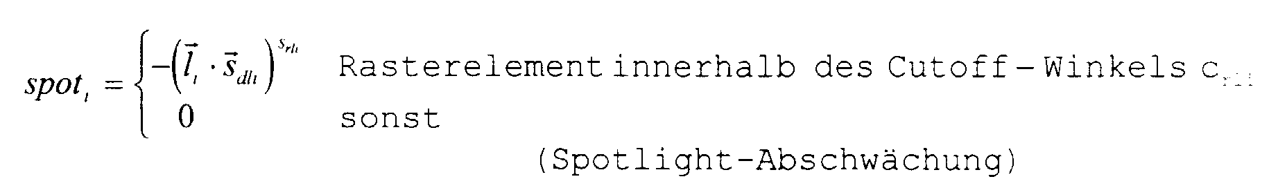
- srli
- Spotlight-Exponent von Lichtquelle i
- crli
- Spotlight-Cutoff-Winkel von Lichtquelle i
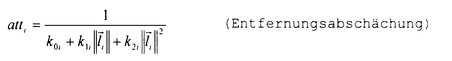
- k0i, k1i, k2i
- konstante, lineare und quadratische Entfernungsabschwächung von Lichtquelle i
- acs
- ambiente Farbe der Szene
Claims (15)
- Bilddarstellungsverfahren zur Darstellung von computermodellierten Objekten, die in Form eines Gittermodells vorliegen und durch mehrere aneinandergrenzende Polygonflächen nachgebildet werden, bei demmittels einer ersten Baugruppe (3, 4) aus einem vorgegebenen, die räumliche Lage jeweils einer der Polygonflächen repräsentierenden ersten Parametersatz eine Vielzahl von ersten Koordinatensätzen berechnet wird, die die räumliche Lage jeweils eines Rasterelements der jeweiligen Polygonfläche repräsentieren,mittels einer zweiten Baugruppe (5, 6) für jedes Rasterelement der Polygonfläche aus dem die räumliche Lage der Polygonfläche repräsentierenden ersten Parametersatz jeweils ein zweiter Koordinatensatz berechnet wird, der die räumliche Lage der lokalen Flächennormale (N) repräsentiert,daß mittels einer dritten Baugruppe (7) aus den die räumliche Lage der einzelnen Rasterelemente repräsentierenden ersten Koordinatensätzen und den die räumliche Lage der lokalen Flächennormale (N) repräsentierenden zweiten Koordinatensätzen und einem vorgegebenen, die räumliche Lage sowie die optischen Eigenschaften mindestens einer ersten Lichtquelle repräsentierenden zweiten Parametersatz sowie einem vorgegebenen, die Position eines virtuellen Betrachters wiedergebenden dritten Parametersatz entsprechend einem lokalen Beleuchtungsmodell ein erster Bildinformationswert berechnet wird, der einen Bildeindruck des jeweiligen Rasterelements aus der Perspektive des Betrachters wiedergibt,mittels einer vierten Baugruppe (14) für jedes Rasterelement aus dem die räumliche Lage des jeweiligen Rasterelements repräsentierenden ersten Koordinatensatz zur Darstellung auf einem Bildschirm (13) ein zweidimensionaler Bildschirmkoordinatensatz berechnet wird, der die Position des Rasterelements auf dem Bildschirm (13) bestimmt,
dadurch gekennzeichnet,daß mittels einer ersten Recheneinheit (10, 11) für die einzelnen Rasterelemente aus den die räumliche Lage der lokalen Flächennormale (N) repräsentierenden zweiten Koordinatensätzen und/oder dem die Position des virtuellen Betrachters bestimmenden dritten Parametersatz sowie dem die räumliche Lage des Rasterelements wiedergebenden ersten Koordinatensatz ein erster Adreßwert berechnet wird,daß mit dem ersten Adreßwert ein Speicherplatz einer ersten Speichermatrix (8, 9) adressiert wird und ein den Bildeindruck der Umgebung aus einer bestimmten Perspektive wiedergebender zweiter Bildinformationswert aus dem adressierten Speicherplatz ausgelesen wird,daß zur Berücksichtigung sowohl des lokalen Beleuchtungsmodells als auch von Reflexionen der Umgebung mittels einer zweiten Recheneinheit (12) aus dem ersten Bildinformationswert und dem zweiten Bildinformationswert ein dritter Bildinformationswert zur Ansteuerung des Bildschirms (13) berechnet wird. - Bilddarstellungsverfahren nach Anspruch 1, dadurch gekennzeichnet,daß aus dem die Position des Betrachters wiedergebenden dritten Parametersatz und dem die räumliche Lage des Rasterelements wiedergebenden ersten Koordinatensatz ein Augvektor (E) berechnet wird, der in der Verbindungslinie zwischen dem Betrachter und dem Rasterelement liegt,daß aus dem Augvektor (E) und dem die räumliche Lage der lokalen Flächennormale (N) repräsentierenden zweiten Koordinatensatz der an dem Rasterelement unter Annahme idealer Spiegelreflexion reflektierte Augvektor (M) berechnet wird,daß der erste Adreßwert aus dem reflektierten Augvektor (M) berechnet wird und den Schnittpunkt des reflektierten Augvektors (M) mit einer das Rasterelement oder die Polygonfläche umgebenden kubischen Hüllfläche repräsentiert, wobei die erste Speichermatrix (8) den im Rahmen von Spiegelreflexion zu berücksichtigen Bildeindruck der Umgebung wiedergibt.
- Bilddarstellungsverfahren nach Anspruch 1 oder 2, dadurch gekennzeichnet,daß mittels einer dritten Recheneinheit (11) aus dem die räumliche Lage der lokalen Flächennormale (N) repräsentierenden zweiten Koordinatensatz ein zweiter Adreßwert berechnet wird, der den Schnittpunkt der lokalen Flächennormale (N) mit einer das Rasterelement oder die Polygonfläche umgebenden kubischen Hüllfläche repräsentiert,daß mit dem zweiten Adreßwert ein Speicherplatz einer zweiten Speichermatrix (9) adressiert und aus dem adressierten Speicherplatz ein vierter Bildinformationswert ausgelesen wird, der einen im Rahmen diffuser Reflexion zu berücksichtigenden Bildeindruck der Umgebung wiedergibt,daß der zur Ansteuerung des Bildschirms (13) dienende dritte Bildinformationswert von der zweiten Recheneinheit (12) aus dem entsprechend dem lokalen Beleuchtungsmodell ermittelten ersten Bildinformationswert und dem spekulare Umgebungsreflexionen wiedergebenden zweiten Bildinformationswert und dem diffuse Umgebungsreflexionen wiedergebenden vierten Bildinformationswert berechnet wird.
- Bilddarstellungsverfahren nach einem der vorhergehenden Ansprüche, dadurch gekennzeichnet, daß der erste Adreßwert und/oder der zweite Adreßwert zur positionsabhängigen Adressierung unterschiedlicher, jeweils verschiedene Umgebungen definierender Speicherbereiche der ersten Speichermatrix (8) und/oder der zweiten Speichermatrix (9) in Abhängigkeit von dem die räumliche Lage der Polygonfläche wiedergebenden ersten Parametersatz oder dem die räumliche Lage des Rasterelements wiedergebenden ersten Koordinatensatz berechnet wird.
- Bilddarstellungsverfahren nach einem der Ansprüche 1 bis 3, dadurch gekennzeichnet, daß zur positionsabhängigen Darstellung unterschiedlicher Umgebungen in Abhängigkeit von dem die räumliche Lage der Polygonfläche wiedergebenden ersten Parametersatz oder dem die räumliche Lage des Rasterelements wiedergebenden ersten Koordinatensatz ein Auswahlwert berechnet wird und die erste Speichermatrix (8) und/oder die zweite Speichermatrix (9) in Abhängigkeit von dem Auswahlwert aus einer Vielzahl von unterschiedliche Umgebungseindrücke definierenden Speichermatrizen ausgewählt wird.
- Bilddarstellungsverfahren nach einem der vorhergehenden Ansprüche, dadurch gekennzeichnet, daß die erste Speichermatrix (8) und/oder die zweite Speichermatrix (9) einen Teilbereich der darzustellenden Umgebung definiert, wobei jedem Raumwinkelbereich der darzustellenden Umgebung ein Speicherplatz der ersten Speichermatrix (8) und/oder ein Speicherplatz der zweiten Speichermatrix (9) eindeutig zugeordnet ist und der erste und/oder der zweite Adreßwert unter der Annahme einer Wiederholung des vorgegebenen Teilbereichs auf der kubischen Hüllfläche berechnet wird.
- Bilddarstellungsverfahren nach Anspruch 6, dadurch gekennzeichnet, daß die in der ersten Speichermatrix (8) abgespeicherten zweiten Bildinformationswerte und/oder die in der zweiten Speichermatrix (9) abgespeicherten vierten Bildinformationswerte von einer vorgegebenen Bildvorlage eingelesen und anschließend zur Erreichung eines natürlichen Bildeindrucks mittels einer Bildverarbeitungseinheit derart verändert werden, daß zwischen benachbarten Teilbereichen entlang der Stoßkante keine Intensitäts- oder Farbsprünge auftreten und/oder die Änderung der Intensitäts-oder Farbwerte über die Stoßkante hinweg konstant ist.
- Bilddarstellungsverfahren nach einem der vorhergehenden Ansprüche, dadurch gekennzeichnet,daß aus dem die räumliche Lage des Rasterelements repräsentierenden ersten Koordinatensatz und dem die räumliche Lage der Polygonfläche repräsentierenden ersten Parametersatz ein dritter Adreßwert berechnet wird, der die Position des Rasterelements innerhalb der Polygonfläche wiedergibt,daß mit dem dritten Adreßwert ein Speicherplatz einer dritten Speichermatrix adressiert wird und ein die Oberflächenstruktur der Polygonfläche definierender fünfter Bildinformationswert aus dem adressierten Speicherplatz ausgelesen wird,daß der zur Ansteuerung des Bildschirms (13) dienende dritte Bildinformationswert von der zweiten Recheneinheit (12) in Abhängigkeit von dem fünften Bildinformationswert berechnet wird.
- Vorrichtung zur Darstellung von computermodellierten Objekten, die in Form eines Gittermodells vorliegen und durch mehrere aneinandergrenzende Polygonflächen nachgebildet sind, insbesondere zur Durchführung des Bilddarstellungsverfahrens nach einem der vorhergehenden Ansprüche, miteiner ersten Baugruppe (3, 4) zur Berechnung einer Vielzahl von die räumliche Lage jeweils eines Rasterelements der jeweiligen Polygonfläche repräsentierenden ersten Koordinatensätzen aus einem vorgegebenen, die der Polygonfläche repräsentierenden ersten Parametersatz,einer zweiten Baugruppe (5, 6) zur Berechnung von die räumliche Lage der lokalen Flächennormalen (N) in den einzelnen Rasterelementen repräsentierenden zweiten Koordinatensätzen in Abhängigkeit von dem ersten Parametersatz,einer dritten Baugruppe (7) zur Berechnung eines den Bildeindruck jeweils eines Rasterelements wiedergebenden ersten Bildinformationswertes entsprechend einem lokalen Beleuchtungsmodell in Abhängigkeit von dem die räumliche Lage des Rasterelements wiedergebenden ersten Koordinatensatz und dem die räumliche Lage der lokalen Flächennormale (N) wiedergebender zweiten Koordinatensatz und einem vorgegebenen, die räumliche Lage und die optischen Eigenschaften mindestens einer Lichtquelle bestimmenden zweiten Parametersatz sowie einem vorgegebenen, die Position eines virtuellen Betrachters bestimmenden dritten Parametersatzes,einer vierten Baugruppe (14) zur Berechnung eines zweidimensionalen Bildschirmkoordinatensatzes für jedes Rasterelement aus dem die räumliche Lage des Rasterelements repräsentierenden ersten Koordinatensatz,
dadurch gekennzeichnet,daß zur Wiedergabe von Reflexionen der Umgebung in der Objektoberfläche eine erste Speichermatrix (8, 9) vorgesehen ist, wobei jeder Speicherplatz der ersten Speichermatrix (8, 9) einen den Bildeindruck der Umgebung aus einer bestimmten Perspektive wiedergebenden zweiten Bildinformationswert enthält,daß zur Berechnung eines ersten Adreßwerts in Abhängigkeit von den die räumliche Lage der lokalen Flächennormale (N) repräsentierenden zweiten Koordinatensätzen und/oder dem die Position des virtuellen Betrachters wiedergebenden dritten Parametersatz sowie dem die räumliche Lage des Rasterelements wiedergebenden ersten Koordinatensatz eine erste Recheneinheit (10, 11) vorgesehen ist, die ausgangsseitig zur Adressierung eines Speicherplatzes mit der ersten Speichermatrix (8, 9) verbunden ist,daß zur Berechnung eines sowohl das lokale Beleuchtungsmodell als auch Reflexionen der Umgebung berücksichtigenden dritten Bildinformationswerts eine zweite Recheneinheit (12) vorgesehen ist, die eingangsseitig zur Aufnahme des dem lokalen Beleuchtungsmodell entsprechenden ersten Bildinformationswerts mit der dritten Baugruppe (7) und zur Aufnahme des die Reflexionen der Umgebung wiedergebenden zweiten Bildinformationswerts mit der ersten Speichermatrix (8, 9) verbunden ist. - Vorrichtung nach Anspruch 9, dadurch gekennzeichnet,daß zur Wiedergabe von diffusen Umgebungsreflexionen eine zweite Speichermatrix (9) vorgesehen ist, wobei jeder Speicherplatz der zweiten Speichermatrix (9) einen vierten Bildinformationswert enthält, der den bei diffuser Reflexion zu berücksichtigenden Bildeindruck der Umgebung enthält,daß zur Berechnung eines zweiten Adreßwertes eine dritte Recheneinheit (11) vorgesehen ist, die eingangsseitig zur Aufnahme des die räumliche Lage der lokalen Flächennormale (N) wiedergebenden zweiten Koordinatensatzes mit der zweiten Baugruppe (6) und ausgangsseitig zur Adressierung mit dem zweiten Adreßwert mit der zweiten Speichermatrix (9) verbunden ist,daß die zweite Recheneinheit (12) eingangsseitig zur Berechnung des zur Ansteuerung des Bildschirms (13) dienenden dritten Bildinformationswertes aus dem entsprechend dem lokalen Beleuchtungsmodell ermittelten ersten Bildinformationswert und dem spekulare Umgebungsreflexionen wiedergebenden zweiten Bildinformationswert und dem diffuse Umgebungsreflexionen wiedergebenden vierten Bildinformationswert mit der zweiten Speichermatrix (9) verbunden ist.
- Vorrichtung nach Anspruch 9 oder 10, dadurch gekennzeichnet,daß zur Berechnung eines von der Position der Polygonfläche oder des Rasterelements abhängigen Auswahlwerts aus dem die räumliche Lage der Polygonfläche wiedergebenden ersten Parametersatz oder aus dem die räumliche Lage des Rasterelements wiedergebenden ersten Koordinatensatz eine vierte Recheneinheit (10, 11) vorgesehen ist,daß die vierte Recheneinheit (10, 11) zur positionsabhängigen Auswahl eines Speicherbereiches mit der ersten und/oder der zweiten Speichermatrix (8, 9) oder zur positionsabhängigen Auswahl der ersten und/oder zweiten Speichermatrix (8, 9) aus einer Vielzahl von Speichermatrizen mit einer Auswahleinheit (10, 11) verbunden ist.
- Vorrichtung nach einem der Ansprüche 9 bis 11, dadurch gekennzeichnet, daß die erste Speichermatrix und/oder die zweite Speichermatrix eine Rundumaufnahme aus der Perspektive des jeweiligen Rasterelements oder der jeweiligen Polygonfläche wiedergibt und jedem Speicherplatz der ersten Speichermatrix und/oder jedem Speicherplatz der zweiten Speichermatrix eineindeutig ein Raumwinkelbereich der darzustellenden Umgebung zugeordnet ist.
- Vorrichtung nach einem der Ansprüche 9 bis 12, dadurch gekennzeichnet,daß die erste Speichermatrix und/oder die zweite Speichermatrix einen Teilbereich der darzustellenden Umgebung definiert, wobei jedem Raumwinkelbereich der darzustellenden Umgebung ein Speicherplatz der ersten Speichermatrix und/oder ein Speicherplatz der zweiten Speichermatrix eindeutig zugeordnet ist,daß zur Adressierung der ersten Speichermatrix und/oder der zweiten Speichermatrix eine erste Adressierungseinheit vorgesehen ist, die eingangsseitig zur Aufnahme des den darzustellenden Raumwinkelbereich der Umgebung bestimmenden ersten oder zweiten Adreßwerts mit der ersten und/oder zweiten Recheneinheit und ausgangsseitig mit der ersten und/oder zweiten Speichermatrix verbunden ist.
- Vorrichtung nach Anspruch 13, dadurch gekennzeichnet, daß die erste Speichermatrix und/oder die zweite Speichermatrix mit einer Bildverarbeitungseinheit verbunden ist, welche die in der ersten Speichermatrix abgespeicherten zweiten Bildinformationswerte und/oder die in der zweiten Speichermatrix abgespeicherten vierten Bildinformationswerte zur Erreichung eines natürlichen Bildeindrucks mittels einer Bildverarbeitungseinheit derart verändert, daß zwischen benachbarten Teilbereichen entlang der Stoßkante keine Intensitäts- oder Farbsprünge auftreten und/oder die Änderung der Intensitäts- oder Farbwerte über die Stoßkante hinweg konstant ist.
- Vorrichtung nach einem der vorhergehenden Ansprüche, dadurch gekennzeichnet,daß zur Nachbildung einer Oberflächenstruktur der jeweiligen Polygonfläche eine dritte Speichermatrix vorgesehen ist, wobei jedem Rasterelement der Polygonfläche ein Speicherplatz der dritten Speichermatrix zugeordnet ist und die einzelnen Speicherplätze der dritten Speichermatrix jeweils einen die Oberflächenstruktur definierenden fünften Bildinformationswert enthalten,daß zur Berechnung eines die räumliche Lage des jeweiligen Rasterelements innerhalb der jeweiligen Polygonfläche wiedergebenden dritten Adreßwerts und zur Adressierung der dritten Speichermatrix mit dem dritten Adreßwert eine zweite Adressierungseinheit vorgesehen ist,daß die zweite Recheneinheit (12) zur Berechnung des zur Ansteuerung des Bildschirms (13) dienenden dritten Bildinformationswerts in Abhängigkeit von dem die Oberflächenstruktur definierenden fünften Bildinformationswert eingangsseitig mit der dritten Speichermatrix verbunden ist.
Applications Claiming Priority (2)
| Application Number | Priority Date | Filing Date | Title |
|---|---|---|---|
| DE19708679A DE19708679A1 (de) | 1997-02-21 | 1997-02-21 | Bilddarstellungsverfahren und Vorrichtung zur Durchführung des Verfahrens |
| DE19708679 | 1997-02-21 |
Publications (2)
| Publication Number | Publication Date |
|---|---|
| EP0862141A2 true EP0862141A2 (de) | 1998-09-02 |
| EP0862141A3 EP0862141A3 (de) | 1999-02-17 |
Family
ID=7822134
Family Applications (1)
| Application Number | Title | Priority Date | Filing Date |
|---|---|---|---|
| EP98250057A Withdrawn EP0862141A3 (de) | 1997-02-21 | 1998-02-17 | Bilddarstellungsverfahren und Vorrichtung zur Durchführung des Verfahrens |
Country Status (3)
| Country | Link |
|---|---|
| US (1) | US6078333A (de) |
| EP (1) | EP0862141A3 (de) |
| DE (1) | DE19708679A1 (de) |
Families Citing this family (30)
| Publication number | Priority date | Publication date | Assignee | Title |
|---|---|---|---|---|
| US6342887B1 (en) * | 1998-11-18 | 2002-01-29 | Earl Robert Munroe | Method and apparatus for reproducing lighting effects in computer animated objects |
| US6525740B1 (en) * | 1999-03-18 | 2003-02-25 | Evans & Sutherland Computer Corporation | System and method for antialiasing bump texture and bump mapping |
| JP2001022917A (ja) * | 1999-07-02 | 2001-01-26 | Namco Ltd | 画像合成方法および装置 |
| US6717577B1 (en) | 1999-10-28 | 2004-04-06 | Nintendo Co., Ltd. | Vertex cache for 3D computer graphics |
| US6618048B1 (en) | 1999-10-28 | 2003-09-09 | Nintendo Co., Ltd. | 3D graphics rendering system for performing Z value clamping in near-Z range to maximize scene resolution of visually important Z components |
| US7119813B1 (en) | 2000-06-02 | 2006-10-10 | Nintendo Co., Ltd. | Variable bit field encoding |
| JP4443012B2 (ja) | 2000-07-27 | 2010-03-31 | 株式会社バンダイナムコゲームス | 画像生成装置、方法および記録媒体 |
| US6811489B1 (en) | 2000-08-23 | 2004-11-02 | Nintendo Co., Ltd. | Controller interface for a graphics system |
| US7196710B1 (en) | 2000-08-23 | 2007-03-27 | Nintendo Co., Ltd. | Method and apparatus for buffering graphics data in a graphics system |
| US6636214B1 (en) | 2000-08-23 | 2003-10-21 | Nintendo Co., Ltd. | Method and apparatus for dynamically reconfiguring the order of hidden surface processing based on rendering mode |
| US6980218B1 (en) | 2000-08-23 | 2005-12-27 | Nintendo Co., Ltd. | Method and apparatus for efficient generation of texture coordinate displacements for implementing emboss-style bump mapping in a graphics rendering system |
| US6937245B1 (en) | 2000-08-23 | 2005-08-30 | Nintendo Co., Ltd. | Graphics system with embedded frame buffer having reconfigurable pixel formats |
| US6867781B1 (en) | 2000-08-23 | 2005-03-15 | Nintendo Co., Ltd. | Graphics pipeline token synchronization |
| US7538772B1 (en) | 2000-08-23 | 2009-05-26 | Nintendo Co., Ltd. | Graphics processing system with enhanced memory controller |
| US7002591B1 (en) | 2000-08-23 | 2006-02-21 | Nintendo Co., Ltd. | Method and apparatus for interleaved processing of direct and indirect texture coordinates in a graphics system |
| US6700586B1 (en) | 2000-08-23 | 2004-03-02 | Nintendo Co., Ltd. | Low cost graphics with stitching processing hardware support for skeletal animation |
| US7576748B2 (en) | 2000-11-28 | 2009-08-18 | Nintendo Co. Ltd. | Graphics system with embedded frame butter having reconfigurable pixel formats |
| US7184059B1 (en) | 2000-08-23 | 2007-02-27 | Nintendo Co., Ltd. | Graphics system with copy out conversions between embedded frame buffer and main memory |
| US6707458B1 (en) | 2000-08-23 | 2004-03-16 | Nintendo Co., Ltd. | Method and apparatus for texture tiling in a graphics system |
| US7034828B1 (en) | 2000-08-23 | 2006-04-25 | Nintendo Co., Ltd. | Recirculating shade tree blender for a graphics system |
| US6825851B1 (en) | 2000-08-23 | 2004-11-30 | Nintendo Co., Ltd. | Method and apparatus for environment-mapped bump-mapping in a graphics system |
| US7061502B1 (en) | 2000-08-23 | 2006-06-13 | Nintendo Co., Ltd. | Method and apparatus for providing logical combination of N alpha operations within a graphics system |
| EP1550381A1 (de) * | 2003-12-23 | 2005-07-06 | 3M Innovative Properties Company | Logiciel de conception pour des vêtement rétroréfléchissants |
| WO2008073449A2 (en) | 2006-12-12 | 2008-06-19 | Evans & Sutherland Computer Corporation | System and method for aligning rgb light in a single modulator projector |
| US20090167762A1 (en) * | 2007-12-26 | 2009-07-02 | Ofer Alon | System and Method for Creating Shaders Via Reference Image Sampling |
| US8358317B2 (en) | 2008-05-23 | 2013-01-22 | Evans & Sutherland Computer Corporation | System and method for displaying a planar image on a curved surface |
| US8702248B1 (en) | 2008-06-11 | 2014-04-22 | Evans & Sutherland Computer Corporation | Projection method for reducing interpixel gaps on a viewing surface |
| US8077378B1 (en) | 2008-11-12 | 2011-12-13 | Evans & Sutherland Computer Corporation | Calibration system and method for light modulation device |
| US9641826B1 (en) | 2011-10-06 | 2017-05-02 | Evans & Sutherland Computer Corporation | System and method for displaying distant 3-D stereo on a dome surface |
| US9965893B2 (en) * | 2013-06-25 | 2018-05-08 | Google Llc. | Curvature-driven normal interpolation for shading applications |
Family Cites Families (2)
| Publication number | Priority date | Publication date | Assignee | Title |
|---|---|---|---|---|
| GB2271259A (en) * | 1992-10-02 | 1994-04-06 | Canon Res Ct Europe Ltd | Processing image data |
| US5923334A (en) * | 1996-08-05 | 1999-07-13 | International Business Machines Corporation | Polyhedral environment map utilizing a triangular data structure |
-
1997
- 1997-02-21 DE DE19708679A patent/DE19708679A1/de not_active Withdrawn
-
1998
- 1998-02-17 EP EP98250057A patent/EP0862141A3/de not_active Withdrawn
- 1998-02-20 US US09/026,694 patent/US6078333A/en not_active Expired - Lifetime
Non-Patent Citations (2)
| Title |
|---|
| GREENE N: "ENVIRONMENT MAPPING AND OTHER APPLICATIONS OF WORLD PROJECTIONS" IEEE COMPUTER GRAPHICS AND APPLICATIONS, NEW YORK, NY, US, Bd. 6, Nr. 11, November 1986, Seiten 21-29, XP000002234 * |
| NISHITA AND NAKAMAE: "CONTINUOUS TONE REPRESENTATION OF THREE-DIMENSIONAL OBJECTS TAKING ACCOUNT OF SHADOWS AND INTERREFLECTION" COMPUTER GRAPHICS, Bd. 19, Nr. 3, Juni 1985, Seiten 23-30, XP002088477 NEW-YORK NY US * |
Also Published As
| Publication number | Publication date |
|---|---|
| DE19708679A1 (de) | 1998-08-27 |
| EP0862141A3 (de) | 1999-02-17 |
| US6078333A (en) | 2000-06-20 |
Similar Documents
| Publication | Publication Date | Title |
|---|---|---|
| EP0862141A2 (de) | Bilddarstellungsverfahren und Vorrichtung zur Durchführung des Verfahrens | |
| EP0789328B1 (de) | Bildverarbeitungsverfahren zur Darstellung von spiegelnden Objekten und zugehörige Vorrichtung | |
| DE69328464T2 (de) | Methode zur Berechnung der Beleuchtung für Daten dreidimensionaler Objekte | |
| DE69329049T2 (de) | Methode zur Verarbeitung von Daten, die dreidimensionale graphische Objekte repräsentieren | |
| EP0984397B1 (de) | Verfahren und Vorrichtung zum Eliminieren unerwünschter Stufungen an Kanten bei Bilddarstellungen im Zeilenraster | |
| DE3855231T2 (de) | Prioritätsauflösungssystem zwischen Polygonen mit Antialiasing | |
| DE10296401B4 (de) | Verbund-Rendering von 3-D-Graphikobjekten | |
| DE112007002991B4 (de) | Computergraphikschattenvolumen unter Verwendung von hierarchischem Okklusions-Culling | |
| DE69331486T2 (de) | Bilddatenverarbeitung | |
| DE69924700T2 (de) | Verfahren zur Darstellung von durch Oberflächenelemente repräsentierten grafischen Objekten | |
| DE3650129T2 (de) | Verfahren zur Kantenglättung für Rechnerbilderzeugungssystem. | |
| DE60107130T2 (de) | Sichtbarkeitsprojektion und Bildrekonstruktion für Oberflächenelemente | |
| DE3854543T2 (de) | Prioritätsverwaltung eines Tiefendatenpuffers für Echtzeitrechnersysteme zur Bilderzeugung. | |
| DE69811849T2 (de) | Verfahren und gerät zur interpolation von attributen bei 3d-grafiken | |
| DE60120474T2 (de) | Rasterung von dreidimensionalen bildern | |
| DE69424716T2 (de) | Verfahren und Vorrichtung zur adaptiven Steuerung der Texturabbildung | |
| DE69714551T2 (de) | Treiberstufe für stereoskopische bildanzeige | |
| DE69127915T2 (de) | System und Verfahren von Prioritätsfarbabbildung | |
| DE68927471T2 (de) | Verfahren zur Schattierung eines graphischen Bildes | |
| DE102005050846A1 (de) | Perspektiveneditierwerkzeuge für 2-D Bilder | |
| DE69230774T2 (de) | Anti-aliasing Tiefenpuffer | |
| DE3854619T2 (de) | Quadratische interpolation zur schattierten bilderzeugung. | |
| EP0865002B1 (de) | Verfahren und Vorrichtung zur Darstellung computermodellierter Objekte | |
| DE19620858B4 (de) | Computergraphiksystem mit Pixel-Tiefenhinweisgebung | |
| DE69420819T2 (de) | Bildverarbeitung |
Legal Events
| Date | Code | Title | Description |
|---|---|---|---|
| PUAI | Public reference made under article 153(3) epc to a published international application that has entered the european phase |
Free format text: ORIGINAL CODE: 0009012 |
|
| AK | Designated contracting states |
Kind code of ref document: A2 Designated state(s): AT CH DE GB LI |
|
| AX | Request for extension of the european patent |
Free format text: AL;LT;LV;MK;RO;SI |
|
| PUAL | Search report despatched |
Free format text: ORIGINAL CODE: 0009013 |
|
| AK | Designated contracting states |
Kind code of ref document: A3 Designated state(s): AT BE CH DE DK ES FI FR GB GR IE IT LI LU MC NL PT SE |
|
| AX | Request for extension of the european patent |
Free format text: AL;LT;LV;MK;RO;SI |
|
| 17P | Request for examination filed |
Effective date: 19990804 |
|
| AKX | Designation fees paid |
Free format text: AT CH DE GB LI |
|
| GRAG | Despatch of communication of intention to grant |
Free format text: ORIGINAL CODE: EPIDOS AGRA |
|
| 17Q | First examination report despatched |
Effective date: 20020416 |
|
| GRAG | Despatch of communication of intention to grant |
Free format text: ORIGINAL CODE: EPIDOS AGRA |
|
| GRAH | Despatch of communication of intention to grant a patent |
Free format text: ORIGINAL CODE: EPIDOS IGRA |
|
| GRAH | Despatch of communication of intention to grant a patent |
Free format text: ORIGINAL CODE: EPIDOS IGRA |
|
| STAA | Information on the status of an ep patent application or granted ep patent |
Free format text: STATUS: THE APPLICATION IS DEEMED TO BE WITHDRAWN |
|
| 18D | Application deemed to be withdrawn |
Effective date: 20021123 |