EP0862082A1 - Multiprojection system - Google Patents
Multiprojection system Download PDFInfo
- Publication number
- EP0862082A1 EP0862082A1 EP97122146A EP97122146A EP0862082A1 EP 0862082 A1 EP0862082 A1 EP 0862082A1 EP 97122146 A EP97122146 A EP 97122146A EP 97122146 A EP97122146 A EP 97122146A EP 0862082 A1 EP0862082 A1 EP 0862082A1
- Authority
- EP
- European Patent Office
- Prior art keywords
- image
- projected
- images
- signal
- projection
- Prior art date
- Legal status (The legal status is an assumption and is not a legal conclusion. Google has not performed a legal analysis and makes no representation as to the accuracy of the status listed.)
- Granted
Links
Images


Classifications
-
- G—PHYSICS
- G09—EDUCATION; CRYPTOGRAPHY; DISPLAY; ADVERTISING; SEALS
- G09F—DISPLAYING; ADVERTISING; SIGNS; LABELS OR NAME-PLATES; SEALS
- G09F19/00—Advertising or display means not otherwise provided for
- G09F19/12—Advertising or display means not otherwise provided for using special optical effects
- G09F19/18—Advertising or display means not otherwise provided for using special optical effects involving the use of optical projection means, e.g. projection of images on clouds
-
- G—PHYSICS
- G03—PHOTOGRAPHY; CINEMATOGRAPHY; ANALOGOUS TECHNIQUES USING WAVES OTHER THAN OPTICAL WAVES; ELECTROGRAPHY; HOLOGRAPHY
- G03B—APPARATUS OR ARRANGEMENTS FOR TAKING PHOTOGRAPHS OR FOR PROJECTING OR VIEWING THEM; APPARATUS OR ARRANGEMENTS EMPLOYING ANALOGOUS TECHNIQUES USING WAVES OTHER THAN OPTICAL WAVES; ACCESSORIES THEREFOR
- G03B37/00—Panoramic or wide-screen photography; Photographing extended surfaces, e.g. for surveying; Photographing internal surfaces, e.g. of pipe
- G03B37/04—Panoramic or wide-screen photography; Photographing extended surfaces, e.g. for surveying; Photographing internal surfaces, e.g. of pipe with cameras or projectors providing touching or overlapping fields of view
-
- F—MECHANICAL ENGINEERING; LIGHTING; HEATING; WEAPONS; BLASTING
- F21—LIGHTING
- F21W—INDEXING SCHEME ASSOCIATED WITH SUBCLASSES F21K, F21L, F21S and F21V, RELATING TO USES OR APPLICATIONS OF LIGHTING DEVICES OR SYSTEMS
- F21W2131/00—Use or application of lighting devices or systems not provided for in codes F21W2102/00-F21W2121/00
- F21W2131/40—Lighting for industrial, commercial, recreational or military use
- F21W2131/406—Lighting for industrial, commercial, recreational or military use for theatres, stages or film studios
Definitions
- This invention relates to a multiprojection system using plural projectors, in which the arrangement and size of images can be freely changed and each image can be freely flown, particularly to a multiprojection system which enables changeful representation as a new screen image system in which a screen image is harmonized with lighting in a representation space.
- projection planes of plural projectors are closely contacted with each other so that the projection planes can be regarded as one large image plane, which is called a projection cube system, a multivision system, videowalls or the like.
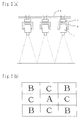
- 12 projector units 96 each having an image plane size of 600 mm (length) x 800 mm (width) are superposed so that three projector units 96 are arranged in lines longitudinally and four projector units 96 are arranged in lines laterally.
- entire image planes form a large image plane having a size of 1,800 mm (length) x 3,200 mm (width).
- a projector 97 is provided in each projector unit 96.
- this system is not limited to the above system using 12 projectors, and by arranging more than 12 projectors in lines longitudinally and laterally, a larger bright image plane can be constituted.
- the same image or different images can be projected by each of the above twelve projectors, or one image can be projected by assigning divided images to all or some of the twelve projectors and arranging and compositing the divided images, so that representation of changeful and various combinations can be provided as compared with a system in which an image is projected on a large image plane only by one projector.
- a technique of moving an image to make representation changeful has been developed.
- the image is moved merely by rotation of one mirror, there is a drawback that the image is inclined in a reverse direction by the angle of a pan angle of the mirror. Therefore, in order to always move the image in a horizontal state, it is necessary to further use a technique of preventing or correcting inclination of the image.
- a problem in the method of the above U.S. patent is that five reflecting planes including the K mirror are given in the example of the above U.S. patent, so that when the reflection efficiencies of the respective mirrors are multiplied, loss of about 50 % of light brightness is caused. That is, when this method is employed in the system of the present invention, brightness is reduced by half to cause a result which is contrary to one object of a multiprojection system, i.e., "a multiprojection system is used in order to ensure brightness".
- lighting has an important meaning.
- a screen image and lighting have been considered to be separate from each other and planned and made by different producers.
- lighting equipments there are a moving light and a mirror scan.
- a starting sheet or a color foil having a pattern which is called GOBO is provided, and the above pattern can be projected as light while the color of the pattern is changed.
- the present invention has been made in order to achieve the above tasks, and an object thereof is to provide a multi-projection system having a possibility of bringing out the creativity of a producer unlimitedly. That is, the means for achieving the tasks of the present invention are as described below.
- an image having a high level can be freely moved without using a conventional moving light or mirror scan, so that a new style of representation in which a screen image is harmonized with lighting or which is positioned between a screen image and lighting can be made.
- Fig. 1(a) is a view showing a state of projection on a side wall of a first embodiment of the multiprojection system of the present invention, and Fig. 1(b) to Fig. 1(g) each show a projected image of the first embodiment.
- Fig. 2(a) is a view showing a state of projection on a floor of a second embodiment of the multiprojection system of the present invention
- Fig. 2(b) shows a projected image of the second embodiment.
- Fig. 3(a) is a view showing an embodiment of moving images freely
- Fig. 3(b) shows a state of flying images
- Fig. 3(c) shows a state of changing the sizes of images and overlapping the images.
- Fig. 4(a) to Fig. 4(c) each show a third embodiment of the multiprojection system of the present invention, in which the sizes of images are changed without causing image distortion.
- Fig. 5(a) is a plane view showing an inner portion seen from an upper side after removing a cover, of a fourth embodiment of the multiprojection system of the present invention
- Fig. 5(b) is a front view showing the structure of a blackout shutter portion of the fourth embodiment
- Fig. 5(c) is a front view showing the structure of a dimming shutter portion.
- Fig. 6 shows an example of a system constitution in the case of multiprojection on 9-screens.
- Fig. 7(b) shows a conventional multiprojection system
- Fig. 7(a) shows a projected image of the conventional multiprojection system.
- Fig. 1(a) is an illustrative view showing the first embodiment using a system of multiprojection on 9-screens as an example in the case where nine projectors are arranged and projection on a side wall is mainly performed.
- Fig. 1(a) 1 is a projector, and an image is projected on, for example, a screen 11 via a projection zoom lens 2.
- Three projectors 1 are arranged longitudinally and laterally, respectively, on extended lines thereof so that nine projectors 1 in total are arranged perpendicularly to the centers of images to be projected.
- the projector 1 is supported by a moving arm 5 in the vicinity of the center of gravity and can be rotated in the longitudinal direction by a tilt driving device 3.
- a pan driving device 7 is provided, which supports the moving arm 5 and is rotatable in the lateral direction.
- pan driving device 7 is supported by an arm 8, and the positions of nine projector units are accurately fixed.
- Each arm 8 is supported by a supporting frame 9 and further fixed to a hanging frame 12 at an upper portion.
- images projected from the nine projectors 1 are arranged as multiprojection on 9-screens on the screen 11.
- the images on the nine planes in this case are "A”.
- an image "A” is projected on the left upper four planes in an enlarged manner, and images on the other five planes are "B”.
- an enlarged image "B” is comprehensively projected on all of the nine planes.
- an image of "A", "B” or "C” is projected on each plane.
- a changeful representation effect is obtained by previously programming such combinations of the kinds and sizes of images along a timing axis and projecting images successively.
- the images on the nine planes have the same size, but there should not be any gap at the respective portions where the images are contacted with each other. That is, it is necessary to make the sizes and positions of the respective images coincident.
- the respective image test charts are shown to check whether X-1, X-2 and X-3 of X axes crossing the middle points of the respective images are straight without any gap of three planes and whether Y-1, Y-2 and Y-3 of Y axes crossing the middle points of the images are straight without any gap of three planes.
- automatic correction is made by comprehensively photographing test chart image planes projected on the nine planes by a CCD (Charge Coupled Device) camera, comparing them with a basic pattern previously memorized in a computer by image processing, quantifying the amount of a gap and inputting the resulting value to pan and tilt driving controllers as pan and tilt driving information.
- CCD Charge Coupled Device
- the sizes of the respective images are adjusted and automatically corrected by, for example, quantifying the overlapping or separating way of the planes which the circles touch and inputting the resulting value to a driving controller of a field angle adjuster (on the premise that the respective projectors are set at predetermined positions).
- test chart explained above is one circle touching the upper and lower sides of the image, but a circle touching the left and right sides of the image may be further added. By these double circles, the gaps of the respective images are made clear to facilitate correction.
- the gaps of the images may be corrected by finely adjusting pan and tilt driving mechanisms or a field angle adjuster by remote control or the like while an operator observes a projected image of the above test chart. Also, depending on the case, the position of the projector 1 relative to the arm 8 may be finely adjusted.
- the first characteristic feature of the present invention resides in that, for example, the arrangement of the images in Fig. 1(c) can be instantaneously changed to the arrangement of the images shown in Fig. 1(g).
- Fig. 1(g) shows an example that representation is made changeful by leaving "A” on four planes, moving three planes of "B” to the right and moving two planes of "B” downward.
- the respective images can be made large or small.
- images are made large or small by changing the pan angles and tilt angles of the projectors 1 except for the projector 1 positioned at the center toward the centers of the images the sizes of which have been changed.
- the screen 11 on which images are to be projected is flat, an entire image is enlarged more toward the left, right, upper and lower edges, so that the entire image is not rectangular.
- the second characteristic feature of the present invention as a second embodiment resides in that, for example, even when an image is mainly projected on a floor, it can be performed by arranging projectors as shown in Fig. 2(a). Each of nine projectors 1 is directly fixed to a hanging frame 22 at an upper portion via a moving arm 5 and a pan driving device 7.
- Fig. 2(b) shows a state that nine planes are gathered at predetermined positions as image arrangement in the case of multiprojection on 9-screens.
- the third characteristic feature of the present invention resides in that the respective images are freely flown.
- Fig. 3(a) shows an example that the projectors 1 except for the projector 1 positioned at the center are rotated laterally. That is, not only a floor but also a wall are projection targets, and images are freely flown thereon to constitute a completely new representation space.
- Fig. 3(b) shows a manner of flying screen images, and their arrangement and combination are not limited at all. For example, eight planes other than one plane may be flown, and the respective three planes may be projected by being divided and moved, which is not shown.
- Such a combination is diversified as the number of planes becomes larger, for example, 12 or 25, and limitless effective representation can be made by the creativity of a director.
- limitless effective representation can be made by the creativity of a director.
- the fourth characteristic feature of the present invention resides in that since the positions and sizes of images can be freely changed and mutual images can be freely overlapped, changeful representation which could not be made in the prior art can be made.
- the sides and positions of images on upper and lower three planes of an image plane of multiprojection on 9-screens are successively changed, and the images are overlapped to express a feeling of depth.
- all of the images are moved with a vanishing point V being fixed (at the center) to enable expression having a further cubic effect.
- the color shades and hues of overlapped images having different sizes may be changed, and also the freely flying images of the present invention may be combined with a large image plane of another fixed projector as a background, which are not shown.
- symbolic expression and a special effect which could not be aimed in the prior art can be aimed.
- the relative positional relation i.e., the arrangement relation of the respective projectors 1 themselves can be changed longitudinally and laterally in order to change the sizes of images by a field angle adjuster as accurately as possible without causing image distortion, which is shown in Fig. 4(a).
- each projector 1 in order to always arrange each projector 1 on a line extended perpendicularly to the center of an image which has been changed, the following moving mechanism is used.
- the projector 1 is fixed to an arm 42 via a moving arm 5 and a pan driving device 7, and the arm 42 is fixed to an elevating carriage 43.
- the elevating carriage 43 has four wheels 44 and guided by the inner side of an elevating frame 48.
- the elevating frame 48 takes charge of longitudinally arranged three projectors 1, and in the case of nine planes, three sets thereof are required.
- a rack gear 47 is arranged at the inner side of the elevating frame 48.
- the rack gear 47 is engaged with a pinion 45 fitted to one of the wheels 44, and the elevating carriage 43 itself is moved upward or downward by rotation of an elevating device 46 provided in the elevating carriage 43.
- the upper edge of the elevating frame 48 is fitted to a running frame 49.
- two running wheels 50 are arranged at the left and right sides, respectively.
- the running wheels 50 are run by being guided by the inner side of a main frame 51 which is hung from a further upper portion.
- the running wheels 50 are rotated and run by a running motor 52 via chain wheels 53 and 54.
- the sizes of images can be accurately changed, and the above problem of causing image distortion can be solved.
- the above moving mechanism can be used.
- the relative positional relation of the respective projectors 1 may be adjusted to be wider in order to further enlarge images so as to have a size larger than that of Fig. 4(b).
- These mechanisms can be arranged in a horizontal direction by changing the fitting direction of the arm 42 relative to the elevating carriage 43 in the case of projection not on a wall but on a floor, and also can be applied to arrangement inclined at 45°.
- a design can be changed so that the angle of the elevating frame 48 can be changed from a perpendicular direction to a horizontal direction non-stepwise.
- the projector 1 may be elevated or lowered by a screw, a block supporting the projector 1 may be elevated or lowered directly by using a linear motor which moves linearly, and movement of the running flame 49 relative to the main flame 51 may be used as a linear motor.
- the driving mechanisms of all of the projectors 1 are the same in consideration of, for example, moving entire images of multiprojection on 9-screens longitudinally and laterally.
- a blackout shutter 57, a dimming shutter 58, a focus adjuster 59, an infrared range finder 60 and a field angle adjuster 61 are provided in front of a projection zoom lens 2 of each projector 1.
- Fig. 5(a) shows an internal constitution seen from an upper side after a cover of an upper face is removed.
- a fitting frame 56 is provided, and at the end of a projection direction of the fitting frame 56, the blackout shutter 57 and the dimming shutter 58 are arranged so that the front face of the projection zoom lens 2 is covered therewith.
- the blackout shutter 57 is provided for the purpose of complete dark change since slight light is transmitted even when light is controlled to the most "black" side in the case where a projector to be used is a liquid crystal projector. However, when a liquid crystal projector is improved by, for example, greatly increasing a liquid crystal contrast ratio, the blackout shutter 57 is not required.
- the blackout shutter 57 is a disk having plural openings a and b, arranged so that the front face of the zoom lens 2 is covered therewith.
- the blackout shutter 57 is supported by a bearing (not shown, hereinafter an explanation regarding a bearing is omitted) supported by the fitting frame 56 and driven by a shutter-rotating motor 62 via a timing belt 63.
- the blackout shutter 57 When the opening a comes in front of the zoom lens 2, the blackout shutter 57 is in an opened state, and when the disk face other than the opening a or b comes in front of the zoom lens 2, it is in a closed state.
- the slightly small opening b is provided in the disk of the blackout shutter 57, and when the opening b comes in front of the zoom lens 2, the brightness of an image to be projected is reduced since the diameter of the opening b is small. That is, the brightness of a screen image when the blackout shutter 57 is in an opened state can be instantaneously changed by switching the openings a or b.
- the dimming shutter 58 is provided for the purpose of smoothly performing switching of the brightness of an image by the so-called fade-in and fade-out at the time of representation.
- the dimming shutter 58 is constituted by two glass plates subjected to gradation treatment for increasing a density successively from the center toward the outside (a left or right end), and each one glass plate is symmetrically arranged at the left and right sides from the center of the zoom lens 2.
- the dimming shutter 58 is movable laterally by being guided by slide rails 64 arranged at the upper and lower sides in parallel with each other.
- One glass plate of the dimming shutter 58 is fixed to the side face at a front side of projection of a timing belt 65 which is set endlessly, and the other glass plate thereof is fixed to the side face at a rear side of projection of the timing belt 65.
- the timing belt 65 is passed between a driving pulley 66 and a free pulley 67.
- the driving pulley 66 is rotated by a shutter-conveying motor 68, and by this rotation, a pair of the glass plates of the dimming shutter 58 fixed to the timing belt 65, respectively, are laterally opened or closed.
- the object can be also achieved by rotating a disk-shaped glass plate subjected to gradation treatment.
- the projection zoom lens 2 of the projector 1 is equipped with the focus adjuster 59.
- the focus adjuster 59 When a distance to an image projection target is not greatly changed, focusing may be previously performed by manual operation. However, when a distance to an image projection target is greatly changed accompanied with movement of an image, the automatic focus adjuster 59 is required.
- the focus adjuster 59 adjusts the focus of a projected image by being rotated by a focus-adjusting motor 69 via a timing belt 70.
- the automatic focus adjuster 59 in this embodiment is used in combination with an automatic range finder. That is, a distance to a screen or a wall, which is changed every moment accompanied with change in a direction of projecting an image, is measured by an automatic range finder, for example, the infrared range finder 60. By a measured signal, the automatic focus adjuster 59 is automatically controlled to enable automatic focusing of an image on a screen or a wall.
- the field angle adjuster 61 adjusts a field angle by rotating the projection zoom lens 2 and changes the size of an image.
- the field angle adjuster 61 is actuated.
- the field angle adjuster 61 is rotated by a field angle-adjusting motor 71 via a timing belt 72 to change the size of a projected image.
- the actuation amount of the field angle adjuster 61 is automatically controlled by a signal from a detector which detects the changed amount of an elevating or running position for moving the projector 1, for example, a rotary encoder (not shown).
- the field angle adjuster 61 is actuated by the above signal from a computer.
- the field angle adjuster 61 may be controlled by a signal of the infrared range finder 60.
- Size Distortion refers to image distortion in its size and/or shape caused in the case where a projection center line of the image projection on a screen is not perpendicular to a projection plane when an image is freely moved.
- Size Distortion refers to image distortion in its size and/or shape caused in the case where a projection center line of the image projection on a screen is not perpendicular to a projection plane when an image is freely moved.
- Size Distortion are adjusted by automatic calculation based on change in an angle in which a pan angle and a tilt angle are synthesized with an angle between a projection center line and a screen or a wall on which an image is to be projected, i.e., the origin being used as a standard.
- Size Distortion can be corrected to an extent which does not constitute an obstacle in practical use.
- a correction principle and calculation thereof reference can be made to a paragraph regarding Size Distortion correction of "Moving projector system" of Japanese Patent Application No. 304337/1995 (Japanese Patent Provisional Publication No. 149296/1997).
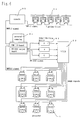
- FIG. 6 An example of a basic system constitution described above is shown in Fig. 6.
- Fig. 6 shows an example of a system constitution in the case of multiprojection on 9-screens, which is a constitution that stress is laid on harmonization of a screen image with lighting. That is, all of the movement control and image control of each projector 1 can be performed from a lighting operation console 90 to improve efficiency such as shortening of a preparation time.
- DMX512 is a signal system in which RS-485 [a signal according to the EIA (Electronics Industries Association) standard] is standardized by USITT (United States Institute for Theatre Technology) for a dimming signal of lighting, in which stress is laid on a digital serial signal-transmitting system.
- This system can transmit signals of 512 channels at the maximum (512 bytes of 00 to FF data) in a cyclic way (about 44 times per second) to a distance of about 1,200 m by a 5-pin "XLR" (popular name; CANNON or Neutrik) cable, which is an extremely simple standard.
- this system has frequently been used not only for controlling a dimming level but also for controlling driving of various parts of the above moving light or the like.
- the following is controlled by the lighting operation console 90.
- 65 ch to 69 ch are assigned to control of starting and stopping of inputting source equipment and materials.
- 70 ch to 74 ch are assigned to switching of outputs "A", "B” and "C" from an image-enlarging basic pattern No. 1 to an image-enlarging basic pattern No. 5.
- 101 ch to 512 ch are assigned to an operation system, a color changer and GOBO.
- the respective 17 channels are assigned to the respective projectors, i.e., 24 projectors at the maximum.
- An example of assigning the respective 17 channels to the respective projectors is shown below.
- 101 ch to 103 ch are assigned to the precision of 3 bytes of pan angle designations 1, 2 and 3, and 104 ch and 105 ch are assigned to the precision of 2 bytes of tilt angle designations 1 and 2.
- 106 ch is assigned to designation of a focus adjustment position
- 107 ch is assigned to designation of a field angle adjustment position
- 108 ch is assigned to designation of a dimming shutter position
- 109 ch is assigned to designation of a blackout shutter position, respectively.
- 110 ch is assigned to switching of internally memorized screen image data and externally inputted screen image data of images.
- 111 ch to 113 ch are assigned to control of internally inputted colors R, G and B, 114 ch is assigned to control of internally inputted contrast, 115 ch is assigned to control of internally inputted luminance, 116 ch is assigned to control of internally inputted GOBO, and 117 ch is assigned to control of internally inputted GOBO rotation, respectively.
- DMX512 signals are sent to a personal computer 91 from the lighting operation console 90, and signals of a driving system, a color changer and GOBO are outputted as DMX512 signals to each projector 1.
- a screen image control signal from the lighting operation console 90 is converted into a RS-232C signal by the personal computer 91 and outputted to each projector 1 after processing and allocation of image enlargement are controlled by MVP (a multiple video processor) 93 which is an image-enlarging device.
- MVP a multiple video processor
- RS-232C is a representative system for transmitting digital signals, i.e., a signal system using a serial transmitting system used for data communication of a computer.
- DMX512 signals are outputted by another system for controlling dimming of common lighting equipments 94, for example, a color changer and lighting.
- the respective lightings are controlled in harmony with movements of the above respective images and projectors, so that a conventional lighting system can be harmonized with a new screen image system.
- all of them can be controlled by one system of DMX512.
- the lighting operation console 90 is not necessarily required.
- the system constitution of Fig. 6 from which the lighting operation console 90 is removed may be employed.
- the personal computer 91 may be designed to have the function of the lighting operation console 90, and data regarding a screen image including a control system can be outputted to each projector 1.
- the signals from the lighting operation console 90 are described as DMX512 signals.
- the object can be achieved by using signals of other serial communication.
- multiprojection on 9-screens is described.
- the present invention can be applied to multiprojection on 12 planes, 25 planes, 100 planes or the like without any problem if, for example, a system in which plural DMX512 systems are used or the numbers of the image-inputting device 92 and the MVP 93 as an image-enlarging device are increased is used.
- the present invention is explained above while stress is mainly laid on harmonization of a screen image with lighting.
- the present invention can be also applied to harmonization of a screen image with sound.
- plural loudspeakers are arranged in a representation space, and the qualities and volumes of sounds from the respective loudspeakers are controlled so as to be changed in harmony with the pan and tilt rotation signals of projectors, i.e., moving images, so that impressive moving stereophonic sound can be reproduced together with a screen image.
- each projector with a sensor which detects a sound wave-generating position
- the projector can be made to face toward a sound wave-generating direction, and by detecting change in the quality and volume of sound, an image can be changed or the color of a color changer can be changed.
- the above tasks in a representation space can be achieved.
- changeful and artistic representation can be made based on an impressive large image plane which can cope with diversification of representation. Also, by harmonization of a screen image with lighting, as new representation, a screen image which enables more complicated and effective representation other than a single pattern level of a moving light or the like can be introduced into the field of lighting.
- a common signal system is used in a screen image control system and a lighting control system, and systems including a screen image system can be controlled from a lighting operation system, so that preparation can be easily performed.
- these means can be supplied as an inexpensive and compact system, and joints of the respective screen images, which is a problem in a conventional system, can be also made as inconspicuous as possible.
Abstract
Description
Claims (6)
- A multiprojection system in which an image can be freely projected by plural projectors so that projected images of the plural projectors are arranged in lines longitudinally and laterally and all of the projected images become one image; an entirely enlarged image or divided images can be projected; or an individual image can be projected, which comprises:each of the plural projectors being provided independently with a pan driving device and a tilt driving device so that the direction of projection can be freely changed; and having at least one of functions of changing the direction of projection, the position of a projected image, the synthesis or arrangement of an image and the size of an image and displaying each image in a flying state to constitute a screen image system harmonized with lighting in a representation space.
- The system according to Claim 1, wherein the relative positional relations of the plural projectors themselves can be each independently changed to change the sizes of projected images without causing image distortion.
- The system according to Claim 1, wherein said system has an additional function that test charts each having at least one circle touching two opposite sides of an image to be projected and at least two straight lines passing the center of the image and crossing at right angles are projected by the plural projectors so that the lines of the images are contacted with each other; the plural test charts projected are comprehensively photographed by a camera; data thereof are inputted to a computer; by image processing, the gaps of the straight lines crossing at right angles and the shapes and sizes of the circles are detected; difference from a basic shape memorized in the computer is converted into a correction signal; and the correction signal is given to the respective projector-driving controllers to automatically correct the gaps and shapes of the images.
- The system according to Claim 1, wherein each of the plural projectors is provided with at least one of a blackout shutter for complete dark change, dimming shutters for fade-in and fade-out, a focus adjuster, a field angle adjuster and a Size Distortion adjuster.
- The system according to Claim 1, wherein focusing of an image to be projected can be always automatically performed accompanied with change in the direction of projection of the image by automatically measuring a distance which changes every moment to a projection target by a distance sensor and automatically controlling a focus adjuster based on a measured value.
- The system according to Claim 1, wherein said system has a control system in which a pan angle-designating signal, a tilt angle-designating signal, a focus position-designating signal, a field angle position-designating signal, a blackout shutter-opening or closing signal, a dimming shutter position-designating signal, a RGB control signal of a color changer, a GOBO image-outputting signal and a GOBO-rotating signal are outputted from a lighting operation console directly to the plural projectors via a computer; and an image-controlling signal is outputted from the lighting operation console to the plural projectors via a computer, an image-inputting device and an image-enlarging device.
Applications Claiming Priority (6)
| Application Number | Priority Date | Filing Date | Title |
|---|---|---|---|
| JP4534997 | 1997-02-28 | ||
| JP4534997 | 1997-02-28 | ||
| JP45349/97 | 1997-02-28 | ||
| JP218573/97 | 1997-08-13 | ||
| JP21857397 | 1997-08-13 | ||
| JP9218573A JPH10301202A (en) | 1997-02-28 | 1997-08-13 | Multiprojection system |
Publications (2)
| Publication Number | Publication Date |
|---|---|
| EP0862082A1 true EP0862082A1 (en) | 1998-09-02 |
| EP0862082B1 EP0862082B1 (en) | 2003-08-06 |
Family
ID=26385322
Family Applications (1)
| Application Number | Title | Priority Date | Filing Date |
|---|---|---|---|
| EP97122146A Expired - Lifetime EP0862082B1 (en) | 1997-02-28 | 1997-12-16 | Multiprojection system |
Country Status (5)
| Country | Link |
|---|---|
| US (1) | US5988817A (en) |
| EP (1) | EP0862082B1 (en) |
| JP (1) | JPH10301202A (en) |
| DE (1) | DE69723953T2 (en) |
| DK (1) | DK0862082T3 (en) |
Cited By (11)
| Publication number | Priority date | Publication date | Assignee | Title |
|---|---|---|---|---|
| EP1141773A1 (en) * | 1998-12-11 | 2001-10-10 | Sony Pictures Entertainment Inc. | Cinema networking system |
| DE10021981A1 (en) * | 2000-05-05 | 2001-12-06 | Organic Theatre Digital Intera | Theatre hall; has walls formed as projection surfaces and image projectors, assigned to projection surfaces with common control center, to project coherent cinema image |
| WO2002049353A1 (en) * | 2000-12-15 | 2002-06-20 | Ms Video Gmbh | Device for generating images |
| WO2005017863A1 (en) * | 2003-08-15 | 2005-02-24 | Delfin Produktion A/S | A method and an arrangement for advertising or promoting |
| EP1978293A1 (en) | 2007-04-03 | 2008-10-08 | ISA Co., Ltd. | Method and system for three-dimensionally staging |
| CN100481908C (en) * | 2006-03-09 | 2009-04-22 | 索尼株式会社 | Apparatus and method for presenting image projection |
| ITMI20101650A1 (en) * | 2010-09-10 | 2012-03-11 | Clay Paky Spa | STAGE PROJECTOR |
| US8311366B2 (en) | 2006-01-13 | 2012-11-13 | Fraunhofer-Gesellschaft zur Förderung der angewandten Forschung e.V. | System and method for calibrating and adjusting a projected image of a projection apparatus |
| CN101393711B (en) * | 2007-09-18 | 2014-08-06 | 精工爱普生株式会社 | Image display apparatus and image display method |
| WO2016015943A1 (en) * | 2014-08-01 | 2016-02-04 | Koninklijke Philips N.V. | System, device for creating an aerial image |
| CN108701440A (en) * | 2016-03-10 | 2018-10-23 | 索尼公司 | Information processing equipment, information processing method and program |
Families Citing this family (86)
| Publication number | Priority date | Publication date | Assignee | Title |
|---|---|---|---|---|
| US20050151941A1 (en) * | 2000-06-16 | 2005-07-14 | Solomon Dennis J. | Advanced performance widget display system |
| US8813137B2 (en) * | 1998-05-08 | 2014-08-19 | Qualcomm Incorporated | Apparatus and method for decoding digital image and audio signals |
| US6220730B1 (en) * | 1998-07-01 | 2001-04-24 | Light & Sound Design, Ltd. | Illumination obscurement device |
| US6362797B1 (en) * | 1999-05-14 | 2002-03-26 | Rockwell Collins, Inc. | Apparatus for aligning multiple projected images in cockpit displays |
| JP2000338941A (en) * | 1999-05-27 | 2000-12-08 | Seiko Epson Corp | Projection type display device |
| US6671005B1 (en) * | 1999-06-21 | 2003-12-30 | Altman Stage Lighting Company | Digital micromirror stage lighting system |
| US6254239B1 (en) * | 1999-07-30 | 2001-07-03 | Raytheon Company | Method and system for image visualization |
| USRE43234E1 (en) | 1999-09-10 | 2012-03-13 | Belliveau Richard S | Method, apparatus and system for image projection lighting |
| US6969960B2 (en) * | 1999-09-10 | 2005-11-29 | Belliveau Richard S | Image projection lighting device |
| US7161562B1 (en) * | 1999-09-22 | 2007-01-09 | Production Resource Group, L.L.C. | Multilayer control of gobo shape |
| WO2001022154A2 (en) * | 1999-09-22 | 2001-03-29 | Light And Sound Design, Ltd. | Multilayer control of gobo shape |
| US9894251B2 (en) | 1999-09-22 | 2018-02-13 | Production Resource Group, L.L.C | Multilayer control of gobo shape |
| US7079157B2 (en) * | 2000-03-17 | 2006-07-18 | Sun Microsystems, Inc. | Matching the edges of multiple overlapping screen images |
| JP3826659B2 (en) * | 2000-03-27 | 2006-09-27 | セイコーエプソン株式会社 | Projection display system and projection display device |
| CA2376411C (en) * | 2000-03-31 | 2009-01-20 | Imax Corporation | Digital projection equipment and techniques |
| WO2001080555A1 (en) | 2000-04-18 | 2001-10-25 | Imax Corporation | Methods and systems for low loss separation and combination of light |
| US8194118B2 (en) * | 2000-06-16 | 2012-06-05 | Dennis J Solomon | Performance display system |
| US20030234914A1 (en) * | 2000-06-16 | 2003-12-25 | Solomon Dennis J. | Autostereoscopic performance wand display system |
| WO2002005553A2 (en) * | 2000-07-03 | 2002-01-17 | Imax Corporation | Equipment and techniques for providing invisible seaming of multiple projection displays |
| US6930681B2 (en) * | 2001-08-14 | 2005-08-16 | Mitsubishi Electric Research Labs, Inc. | System and method for registering multiple images with three-dimensional objects |
| US6520649B1 (en) * | 2002-01-07 | 2003-02-18 | Mcnc | Image projection device and associated method |
| US6812653B2 (en) * | 2002-07-26 | 2004-11-02 | Richard S. Bellivean | Method and apparatus for controlling images with image projection lighting devices |
| JP2004072570A (en) * | 2002-08-08 | 2004-03-04 | Casio Comput Co Ltd | Display controller, information terminal device and display control program |
| US20060007406A1 (en) * | 2002-10-21 | 2006-01-12 | Sean Adkins | Equipment, systems and methods for control of color in projection displays |
| US7390092B2 (en) * | 2002-11-08 | 2008-06-24 | Belliveau Richard S | Image projection lighting devices with visible and infrared imaging |
| US7206023B2 (en) * | 2002-12-13 | 2007-04-17 | Belliveau Richard S | Image projection lighting devices with projection field light intensity uniformity adjustment |
| US6988807B2 (en) * | 2003-02-07 | 2006-01-24 | Belliveau Richard S | Theatrical fog particle protection system for image projection lighting devices |
| US6982529B2 (en) * | 2003-02-07 | 2006-01-03 | Belliveau Richard S | Method of lamp replacement warning for image projection lighting devices |
| US6927545B2 (en) * | 2003-03-10 | 2005-08-09 | Richard S. Belliveau | Image projection lighting device displays and interactive images |
| JP4400200B2 (en) * | 2003-12-10 | 2010-01-20 | セイコーエプソン株式会社 | Image display method, image display apparatus, and image display program |
| US7018047B2 (en) * | 2004-01-27 | 2006-03-28 | Belliveau Richard S | Image projection lighting device with variable homogeneity |
| US7055963B2 (en) * | 2004-03-01 | 2006-06-06 | Belliveau Richard S | Content optimizing system for an image projection lighting device |
| US8251512B2 (en) * | 2004-07-08 | 2012-08-28 | Imax Corporation | Equipment and methods for the display of high resolution images using multiple projection displays |
| WO2006077665A1 (en) * | 2005-01-20 | 2006-07-27 | National University Corporation NARA Institute of Science and Technology | Projection device, control method for projection device, composite projection system, control program for projection device, and recording medium having projection device control program recorded therein |
| JP2008539675A (en) * | 2005-04-26 | 2008-11-13 | アイマックス コーポレイション | Electronic projection system and method |
| JP4626416B2 (en) * | 2005-06-20 | 2011-02-09 | セイコーエプソン株式会社 | projector |
| CA2632056C (en) | 2005-12-06 | 2014-01-14 | Dolby Laboratories Licensing Corporation | Modular electronic displays |
| US8976080B2 (en) | 2005-12-06 | 2015-03-10 | Dolby Laboratories Licensing Corporation | Multi-segment imager |
| US8478386B2 (en) | 2006-01-10 | 2013-07-02 | Accuvein Inc. | Practitioner-mounted micro vein enhancer |
| US11253198B2 (en) | 2006-01-10 | 2022-02-22 | Accuvein, Inc. | Stand-mounted scanned laser vein contrast enhancer |
| US11278240B2 (en) | 2006-01-10 | 2022-03-22 | Accuvein, Inc. | Trigger-actuated laser vein contrast enhancer |
| US8489178B2 (en) | 2006-06-29 | 2013-07-16 | Accuvein Inc. | Enhanced laser vein contrast enhancer with projection of analyzed vein data |
| US8838210B2 (en) | 2006-06-29 | 2014-09-16 | AccuView, Inc. | Scanned laser vein contrast enhancer using a single laser |
| US10813588B2 (en) | 2006-01-10 | 2020-10-27 | Accuvein, Inc. | Micro vein enhancer |
| US9854977B2 (en) | 2006-01-10 | 2018-01-02 | Accuvein, Inc. | Scanned laser vein contrast enhancer using a single laser, and modulation circuitry |
| US9492117B2 (en) | 2006-01-10 | 2016-11-15 | Accuvein, Inc. | Practitioner-mounted micro vein enhancer |
| US8255040B2 (en) | 2006-06-29 | 2012-08-28 | Accuvein, Llc | Micro vein enhancer |
| US7748878B2 (en) * | 2006-05-18 | 2010-07-06 | Production Resource Group, Inc. | Lighting control system with wireless network connection |
| US7794094B2 (en) * | 2006-05-26 | 2010-09-14 | Sony Corporation | System and method for multi-directional positioning of projected images |
| US7635188B2 (en) * | 2006-06-06 | 2009-12-22 | Barco Lighting Systems, Inc. | Method and apparatus for creating a collage from a plurality of stage lights |
| US8463364B2 (en) * | 2009-07-22 | 2013-06-11 | Accuvein Inc. | Vein scanner |
| US8594770B2 (en) * | 2006-06-29 | 2013-11-26 | Accuvein, Inc. | Multispectral detection and presentation of an object's characteristics |
| US10238294B2 (en) | 2006-06-29 | 2019-03-26 | Accuvein, Inc. | Scanned laser vein contrast enhancer using one laser |
| US8730321B2 (en) | 2007-06-28 | 2014-05-20 | Accuvein, Inc. | Automatic alignment of a contrast enhancement system |
| US8665507B2 (en) * | 2006-06-29 | 2014-03-04 | Accuvein, Inc. | Module mounting mirror endoscopy |
| US20080007400A1 (en) * | 2006-07-07 | 2008-01-10 | Terry Murphy | Image projection system |
| US7901096B2 (en) * | 2006-07-17 | 2011-03-08 | Dorsey Metrology International | Illumination for projecting an image |
| US8328368B2 (en) * | 2007-04-26 | 2012-12-11 | Accuvein Inc. | Projection system |
| US7954954B2 (en) * | 2007-07-31 | 2011-06-07 | Hewlett-Packard Development Company, L.P. | System and method of projecting an image using a plurality of projectors |
| US9061109B2 (en) | 2009-07-22 | 2015-06-23 | Accuvein, Inc. | Vein scanner with user interface |
| JP5499625B2 (en) * | 2009-10-26 | 2014-05-21 | セイコーエプソン株式会社 | Image projection system and control method of image projection system |
| JP5454325B2 (en) * | 2009-11-18 | 2014-03-26 | セイコーエプソン株式会社 | Image forming apparatus |
| JP5793691B2 (en) * | 2010-07-02 | 2015-10-14 | パナソニックIpマネジメント株式会社 | Projection display device |
| US20120147342A1 (en) * | 2010-12-14 | 2012-06-14 | National Chiao Tung University | Projection apparatus |
| JP5454540B2 (en) * | 2011-09-30 | 2014-03-26 | ブラザー工業株式会社 | Image reading device |
| US8770764B2 (en) | 2012-01-16 | 2014-07-08 | Barco Lighting Systems, Inc. | Programmable de-fogger system for a light projector |
| PL2820847T3 (en) | 2012-02-27 | 2020-06-29 | Dolby Laboratories Licensing Corporation | Multi-segment imager |
| US9072426B2 (en) | 2012-08-02 | 2015-07-07 | AccuVein, Inc | Device for detecting and illuminating vasculature using an FPGA |
| JP5966878B2 (en) | 2012-11-20 | 2016-08-10 | ブラザー工業株式会社 | Image reading device |
| US10376148B2 (en) | 2012-12-05 | 2019-08-13 | Accuvein, Inc. | System and method for laser imaging and ablation of cancer cells using fluorescence |
| US20140218695A1 (en) * | 2013-02-01 | 2014-08-07 | 3M Innovative Properties Company | Orthogonally disposed projection surfaces |
| JP6118624B2 (en) * | 2013-04-16 | 2017-04-19 | 日本放送協会 | Multi-projector system and multi-projector adjustment method |
| JP2013218346A (en) * | 2013-05-30 | 2013-10-24 | Denso Corp | Method for manufacturing head-up display device and virtual image adjustment device suitable for using the same manufacturing method |
| KR101526294B1 (en) * | 2013-08-26 | 2015-06-05 | 씨제이씨지브이 주식회사 | Apparatus and method for generating guide image using parameter |
| US9800845B2 (en) * | 2014-02-07 | 2017-10-24 | Microsoft Technology Licensing, Llc | Projector-based crowd coordination and messaging |
| JP2015154370A (en) * | 2014-02-18 | 2015-08-24 | 株式会社リコー | Multi-projection system and voice output method |
| WO2015141128A1 (en) * | 2014-03-20 | 2015-09-24 | パナソニックIpマネジメント株式会社 | Projector control device, multi-projector system, and projector control method |
| JP6115880B2 (en) | 2014-03-24 | 2017-04-19 | パナソニックIpマネジメント株式会社 | Projector control apparatus, projector system, and projector control method |
| US9972131B2 (en) * | 2014-06-03 | 2018-05-15 | Intel Corporation | Projecting a virtual image at a physical surface |
| CN114849250A (en) | 2014-11-30 | 2022-08-05 | 杜比实验室特许公司 | Large format theater design for social media linking |
| US9551161B2 (en) * | 2014-11-30 | 2017-01-24 | Dolby Laboratories Licensing Corporation | Theater entrance |
| CN106331549A (en) * | 2015-06-30 | 2017-01-11 | 中强光电股份有限公司 | Projection apparatus |
| JP6432002B2 (en) * | 2016-03-09 | 2018-11-28 | 富士フイルム株式会社 | Projection display device, projection control method, projection control program |
| WO2021256423A1 (en) * | 2020-06-18 | 2021-12-23 | パナソニックIpマネジメント株式会社 | Video projection method and video projection system |
| JP7137609B2 (en) * | 2020-12-11 | 2022-09-14 | Idec株式会社 | Illuminated display device |
| JP2022186091A (en) | 2021-06-04 | 2022-12-15 | セイコーエプソン株式会社 | Method for controlling display, controller, and display device |
Citations (7)
| Publication number | Priority date | Publication date | Assignee | Title |
|---|---|---|---|---|
| US4392187A (en) * | 1981-03-02 | 1983-07-05 | Vari-Lite, Ltd. | Computer controlled lighting system having automatically variable position, color, intensity and beam divergence |
| US4980806A (en) * | 1986-07-17 | 1990-12-25 | Vari-Lite, Inc. | Computer controlled lighting system with distributed processing |
| US5029992A (en) * | 1988-07-26 | 1991-07-09 | Morpheus Lights, Inc. | Motor-controlled lens system |
| JPH0519346A (en) * | 1991-06-18 | 1993-01-29 | Matsushita Electric Ind Co Ltd | Projection type image display device |
| US5206760A (en) * | 1990-10-01 | 1993-04-27 | Hitachi, Ltd. | Multiprojection apparatus |
| US5365288A (en) * | 1992-10-01 | 1994-11-15 | Advanced Laser Projection, Inc. | Image mover |
| JPH0854593A (en) * | 1994-08-15 | 1996-02-27 | Toshiba Corp | Multi-projector |
Family Cites Families (5)
| Publication number | Priority date | Publication date | Assignee | Title |
|---|---|---|---|---|
| US3359855A (en) * | 1966-09-09 | 1967-12-26 | James E Webb | Optical projector system |
| US3602582A (en) * | 1968-09-11 | 1971-08-31 | Ngo Torricelli | Triptych cinematographic system |
| US3749484A (en) * | 1969-03-03 | 1973-07-31 | K Busche | Programmed illumination of panel display sections |
| US5085495A (en) * | 1990-02-28 | 1992-02-04 | Hitachi, Ltd. | Multi-screen projector |
| DE4244448C2 (en) * | 1992-12-23 | 1995-04-13 | Krone Ag | Method and arrangement for the optical representation of information |
-
1997
- 1997-08-13 JP JP9218573A patent/JPH10301202A/en active Pending
- 1997-12-08 US US08/986,807 patent/US5988817A/en not_active Expired - Fee Related
- 1997-12-16 DE DE69723953T patent/DE69723953T2/en not_active Expired - Fee Related
- 1997-12-16 EP EP97122146A patent/EP0862082B1/en not_active Expired - Lifetime
- 1997-12-16 DK DK97122146T patent/DK0862082T3/en active
Patent Citations (7)
| Publication number | Priority date | Publication date | Assignee | Title |
|---|---|---|---|---|
| US4392187A (en) * | 1981-03-02 | 1983-07-05 | Vari-Lite, Ltd. | Computer controlled lighting system having automatically variable position, color, intensity and beam divergence |
| US4980806A (en) * | 1986-07-17 | 1990-12-25 | Vari-Lite, Inc. | Computer controlled lighting system with distributed processing |
| US5029992A (en) * | 1988-07-26 | 1991-07-09 | Morpheus Lights, Inc. | Motor-controlled lens system |
| US5206760A (en) * | 1990-10-01 | 1993-04-27 | Hitachi, Ltd. | Multiprojection apparatus |
| JPH0519346A (en) * | 1991-06-18 | 1993-01-29 | Matsushita Electric Ind Co Ltd | Projection type image display device |
| US5365288A (en) * | 1992-10-01 | 1994-11-15 | Advanced Laser Projection, Inc. | Image mover |
| JPH0854593A (en) * | 1994-08-15 | 1996-02-27 | Toshiba Corp | Multi-projector |
Non-Patent Citations (2)
| Title |
|---|
| PATENT ABSTRACTS OF JAPAN vol. 017, no. 290 (P - 1549) 3 June 1993 (1993-06-03) * |
| PATENT ABSTRACTS OF JAPAN vol. 096, no. 006 28 June 1996 (1996-06-28) * |
Cited By (16)
| Publication number | Priority date | Publication date | Assignee | Title |
|---|---|---|---|---|
| EP1141773A1 (en) * | 1998-12-11 | 2001-10-10 | Sony Pictures Entertainment Inc. | Cinema networking system |
| EP1141773A4 (en) * | 1998-12-11 | 2007-06-27 | Sony Pictures Entertainment | Cinema networking system |
| DE10021981A1 (en) * | 2000-05-05 | 2001-12-06 | Organic Theatre Digital Intera | Theatre hall; has walls formed as projection surfaces and image projectors, assigned to projection surfaces with common control center, to project coherent cinema image |
| DE10021981C2 (en) * | 2000-05-05 | 2003-08-21 | Organic Theatre Digital Intera | theater |
| WO2002049353A1 (en) * | 2000-12-15 | 2002-06-20 | Ms Video Gmbh | Device for generating images |
| WO2005017863A1 (en) * | 2003-08-15 | 2005-02-24 | Delfin Produktion A/S | A method and an arrangement for advertising or promoting |
| US8311366B2 (en) | 2006-01-13 | 2012-11-13 | Fraunhofer-Gesellschaft zur Förderung der angewandten Forschung e.V. | System and method for calibrating and adjusting a projected image of a projection apparatus |
| CN100481908C (en) * | 2006-03-09 | 2009-04-22 | 索尼株式会社 | Apparatus and method for presenting image projection |
| US7918584B2 (en) | 2007-04-03 | 2011-04-05 | Isa Co., Ltd. | Method and system for three-dimensionally staging |
| EP1978293A1 (en) | 2007-04-03 | 2008-10-08 | ISA Co., Ltd. | Method and system for three-dimensionally staging |
| CN101393711B (en) * | 2007-09-18 | 2014-08-06 | 精工爱普生株式会社 | Image display apparatus and image display method |
| ITMI20101650A1 (en) * | 2010-09-10 | 2012-03-11 | Clay Paky Spa | STAGE PROJECTOR |
| WO2016015943A1 (en) * | 2014-08-01 | 2016-02-04 | Koninklijke Philips N.V. | System, device for creating an aerial image |
| US10068506B2 (en) | 2014-08-01 | 2018-09-04 | Philips Lighting Holding B.V. | System, device for creating an aerial image |
| CN108701440A (en) * | 2016-03-10 | 2018-10-23 | 索尼公司 | Information processing equipment, information processing method and program |
| CN108701440B (en) * | 2016-03-10 | 2021-10-15 | 索尼公司 | Information processing apparatus, information processing method, and program |
Also Published As
| Publication number | Publication date |
|---|---|
| JPH10301202A (en) | 1998-11-13 |
| DE69723953D1 (en) | 2003-09-11 |
| EP0862082B1 (en) | 2003-08-06 |
| US5988817A (en) | 1999-11-23 |
| DK0862082T3 (en) | 2003-12-01 |
| DE69723953T2 (en) | 2004-07-15 |
Similar Documents
| Publication | Publication Date | Title |
|---|---|---|
| US5988817A (en) | Multiprojection system | |
| US6765544B1 (en) | Image projection apparatus and method with viewing surface dependent image correction | |
| US7374288B2 (en) | Image projection lighting device | |
| US20040196362A1 (en) | Display apparatus | |
| KR19990076596A (en) | Microscope Lighting | |
| US6523956B2 (en) | Multiplexed motion picture camera | |
| US5801812A (en) | 3D photographic printer using a digital micro-mirror device for exposure | |
| US20070279600A1 (en) | Method and apparatus for creating a collage from a plurality of stage lights | |
| JPH02290388A (en) | Apparatus and method for converting picture or copy into video signal | |
| CN102753884A (en) | Improved diffusion system for an automated luminaire | |
| US5801811A (en) | 3D photographic printer using a matrix display for exposure | |
| US20030025649A1 (en) | Image projection apparatus | |
| US20180213220A1 (en) | Camera testing apparatus and method | |
| US3867022A (en) | Cineconversion machine | |
| EP1636646A2 (en) | Image projector with means for changing direction and/or magnification of image beam | |
| JP3117303B2 (en) | Optical device | |
| CN1542670A (en) | Special effect stage theatre system | |
| US20050209012A1 (en) | Illumination system | |
| US20230328194A1 (en) | Background display device | |
| US7011429B2 (en) | Color modifying effects for image projection lighting devices | |
| Blasko | Motion Pictures | |
| CN1021497C (en) | Apparatus and method for converting pictures or images into video signals | |
| CN2549671Y (en) | Automatic pickup camera head rotating device of video display table | |
| JPH01200795A (en) | Color picture projection device | |
| JPH08328171A (en) | Stereoscopic image input device and its input method |
Legal Events
| Date | Code | Title | Description |
|---|---|---|---|
| PUAI | Public reference made under article 153(3) epc to a published international application that has entered the european phase |
Free format text: ORIGINAL CODE: 0009012 |
|
| AK | Designated contracting states |
Kind code of ref document: A1 Designated state(s): DE DK FR GB IT SE |
|
| AX | Request for extension of the european patent |
Free format text: AL;LT;LV;MK;RO;SI |
|
| 17P | Request for examination filed |
Effective date: 19990114 |
|
| AKX | Designation fees paid |
Free format text: DE DK FR GB IT SE |
|
| RBV | Designated contracting states (corrected) |
Designated state(s): DE DK FR GB IT SE |
|
| 17Q | First examination report despatched |
Effective date: 19991124 |
|
| GRAH | Despatch of communication of intention to grant a patent |
Free format text: ORIGINAL CODE: EPIDOS IGRA |
|
| GRAH | Despatch of communication of intention to grant a patent |
Free format text: ORIGINAL CODE: EPIDOS IGRA |
|
| GRAA | (expected) grant |
Free format text: ORIGINAL CODE: 0009210 |
|
| AK | Designated contracting states |
Designated state(s): DE DK FR GB IT SE |
|
| REG | Reference to a national code |
Ref country code: GB Ref legal event code: FG4D |
|
| RIC1 | Information provided on ipc code assigned before grant |
Ipc: 7G 09F 19/18 B Ipc: 7F 21S 8/00 B Ipc: 7G 03B 21/00 B Ipc: 7G 03B 37/04 A |
|
| REF | Corresponds to: |
Ref document number: 69723953 Country of ref document: DE Date of ref document: 20030911 Kind code of ref document: P |
|
| REG | Reference to a national code |
Ref country code: SE Ref legal event code: TRGR |
|
| REG | Reference to a national code |
Ref country code: DK Ref legal event code: T3 |
|
| ET | Fr: translation filed | ||
| PLBE | No opposition filed within time limit |
Free format text: ORIGINAL CODE: 0009261 |
|
| STAA | Information on the status of an ep patent application or granted ep patent |
Free format text: STATUS: NO OPPOSITION FILED WITHIN TIME LIMIT |
|
| 26N | No opposition filed |
Effective date: 20040507 |
|
| PGFP | Annual fee paid to national office [announced via postgrant information from national office to epo] |
Ref country code: DK Payment date: 20071220 Year of fee payment: 11 |
|
| PGFP | Annual fee paid to national office [announced via postgrant information from national office to epo] |
Ref country code: IT Payment date: 20071220 Year of fee payment: 11 |
|
| PGFP | Annual fee paid to national office [announced via postgrant information from national office to epo] |
Ref country code: SE Payment date: 20071219 Year of fee payment: 11 |
|
| PGFP | Annual fee paid to national office [announced via postgrant information from national office to epo] |
Ref country code: GB Payment date: 20071219 Year of fee payment: 11 |
|
| PGFP | Annual fee paid to national office [announced via postgrant information from national office to epo] |
Ref country code: DE Payment date: 20071220 Year of fee payment: 11 |
|
| PGFP | Annual fee paid to national office [announced via postgrant information from national office to epo] |
Ref country code: FR Payment date: 20071214 Year of fee payment: 11 |
|
| REG | Reference to a national code |
Ref country code: DK Ref legal event code: EBP |
|
| EUG | Se: european patent has lapsed | ||
| GBPC | Gb: european patent ceased through non-payment of renewal fee |
Effective date: 20081216 |
|
| REG | Reference to a national code |
Ref country code: FR Ref legal event code: ST Effective date: 20090831 |
|
| PG25 | Lapsed in a contracting state [announced via postgrant information from national office to epo] |
Ref country code: DE Free format text: LAPSE BECAUSE OF NON-PAYMENT OF DUE FEES Effective date: 20090701 |
|
| PG25 | Lapsed in a contracting state [announced via postgrant information from national office to epo] |
Ref country code: GB Free format text: LAPSE BECAUSE OF NON-PAYMENT OF DUE FEES Effective date: 20081216 |
|
| PG25 | Lapsed in a contracting state [announced via postgrant information from national office to epo] |
Ref country code: DK Free format text: LAPSE BECAUSE OF NON-PAYMENT OF DUE FEES Effective date: 20090105 |
|
| PG25 | Lapsed in a contracting state [announced via postgrant information from national office to epo] |
Ref country code: FR Free format text: LAPSE BECAUSE OF NON-PAYMENT OF DUE FEES Effective date: 20081231 |
|
| PG25 | Lapsed in a contracting state [announced via postgrant information from national office to epo] |
Ref country code: SE Free format text: LAPSE BECAUSE OF NON-PAYMENT OF DUE FEES Effective date: 20081217 |
|
| PG25 | Lapsed in a contracting state [announced via postgrant information from national office to epo] |
Ref country code: IT Free format text: LAPSE BECAUSE OF NON-PAYMENT OF DUE FEES Effective date: 20081216 |