EP0861992B1 - Constant velocity universal joint - Google Patents
Constant velocity universal joint Download PDFInfo
- Publication number
- EP0861992B1 EP0861992B1 EP98102222A EP98102222A EP0861992B1 EP 0861992 B1 EP0861992 B1 EP 0861992B1 EP 98102222 A EP98102222 A EP 98102222A EP 98102222 A EP98102222 A EP 98102222A EP 0861992 B1 EP0861992 B1 EP 0861992B1
- Authority
- EP
- European Patent Office
- Prior art keywords
- constant velocity
- universal joint
- velocity universal
- flat surface
- spherical
- Prior art date
- Legal status (The legal status is an assumption and is not a legal conclusion. Google has not performed a legal analysis and makes no representation as to the accuracy of the status listed.)
- Expired - Lifetime
Links
Images


Classifications
-
- F—MECHANICAL ENGINEERING; LIGHTING; HEATING; WEAPONS; BLASTING
- F16—ENGINEERING ELEMENTS AND UNITS; GENERAL MEASURES FOR PRODUCING AND MAINTAINING EFFECTIVE FUNCTIONING OF MACHINES OR INSTALLATIONS; THERMAL INSULATION IN GENERAL
- F16D—COUPLINGS FOR TRANSMITTING ROTATION; CLUTCHES; BRAKES
- F16D3/00—Yielding couplings, i.e. with means permitting movement between the connected parts during the drive
- F16D3/16—Universal joints in which flexibility is produced by means of pivots or sliding or rolling connecting parts
- F16D3/20—Universal joints in which flexibility is produced by means of pivots or sliding or rolling connecting parts one coupling part entering a sleeve of the other coupling part and connected thereto by sliding or rolling members
- F16D3/202—Universal joints in which flexibility is produced by means of pivots or sliding or rolling connecting parts one coupling part entering a sleeve of the other coupling part and connected thereto by sliding or rolling members one coupling part having radially projecting pins, e.g. tripod joints
- F16D3/205—Universal joints in which flexibility is produced by means of pivots or sliding or rolling connecting parts one coupling part entering a sleeve of the other coupling part and connected thereto by sliding or rolling members one coupling part having radially projecting pins, e.g. tripod joints the pins extending radially outwardly from the coupling part
- F16D3/2055—Universal joints in which flexibility is produced by means of pivots or sliding or rolling connecting parts one coupling part entering a sleeve of the other coupling part and connected thereto by sliding or rolling members one coupling part having radially projecting pins, e.g. tripod joints the pins extending radially outwardly from the coupling part having three pins, i.e. true tripod joints
-
- F—MECHANICAL ENGINEERING; LIGHTING; HEATING; WEAPONS; BLASTING
- F16—ENGINEERING ELEMENTS AND UNITS; GENERAL MEASURES FOR PRODUCING AND MAINTAINING EFFECTIVE FUNCTIONING OF MACHINES OR INSTALLATIONS; THERMAL INSULATION IN GENERAL
- F16D—COUPLINGS FOR TRANSMITTING ROTATION; CLUTCHES; BRAKES
- F16D3/00—Yielding couplings, i.e. with means permitting movement between the connected parts during the drive
- F16D3/16—Universal joints in which flexibility is produced by means of pivots or sliding or rolling connecting parts
- F16D3/20—Universal joints in which flexibility is produced by means of pivots or sliding or rolling connecting parts one coupling part entering a sleeve of the other coupling part and connected thereto by sliding or rolling members
- F16D3/202—Universal joints in which flexibility is produced by means of pivots or sliding or rolling connecting parts one coupling part entering a sleeve of the other coupling part and connected thereto by sliding or rolling members one coupling part having radially projecting pins, e.g. tripod joints
- F16D3/205—Universal joints in which flexibility is produced by means of pivots or sliding or rolling connecting parts one coupling part entering a sleeve of the other coupling part and connected thereto by sliding or rolling members one coupling part having radially projecting pins, e.g. tripod joints the pins extending radially outwardly from the coupling part
- F16D3/2052—Universal joints in which flexibility is produced by means of pivots or sliding or rolling connecting parts one coupling part entering a sleeve of the other coupling part and connected thereto by sliding or rolling members one coupling part having radially projecting pins, e.g. tripod joints the pins extending radially outwardly from the coupling part having two pins
-
- F—MECHANICAL ENGINEERING; LIGHTING; HEATING; WEAPONS; BLASTING
- F16—ENGINEERING ELEMENTS AND UNITS; GENERAL MEASURES FOR PRODUCING AND MAINTAINING EFFECTIVE FUNCTIONING OF MACHINES OR INSTALLATIONS; THERMAL INSULATION IN GENERAL
- F16D—COUPLINGS FOR TRANSMITTING ROTATION; CLUTCHES; BRAKES
- F16D3/00—Yielding couplings, i.e. with means permitting movement between the connected parts during the drive
- F16D3/16—Universal joints in which flexibility is produced by means of pivots or sliding or rolling connecting parts
- F16D3/20—Universal joints in which flexibility is produced by means of pivots or sliding or rolling connecting parts one coupling part entering a sleeve of the other coupling part and connected thereto by sliding or rolling members
- F16D3/202—Universal joints in which flexibility is produced by means of pivots or sliding or rolling connecting parts one coupling part entering a sleeve of the other coupling part and connected thereto by sliding or rolling members one coupling part having radially projecting pins, e.g. tripod joints
- F16D2003/2023—Universal joints in which flexibility is produced by means of pivots or sliding or rolling connecting parts one coupling part entering a sleeve of the other coupling part and connected thereto by sliding or rolling members one coupling part having radially projecting pins, e.g. tripod joints with linear rolling bearings between raceway and trunnion mounted shoes
-
- Y—GENERAL TAGGING OF NEW TECHNOLOGICAL DEVELOPMENTS; GENERAL TAGGING OF CROSS-SECTIONAL TECHNOLOGIES SPANNING OVER SEVERAL SECTIONS OF THE IPC; TECHNICAL SUBJECTS COVERED BY FORMER USPC CROSS-REFERENCE ART COLLECTIONS [XRACs] AND DIGESTS
- Y10—TECHNICAL SUBJECTS COVERED BY FORMER USPC
- Y10S—TECHNICAL SUBJECTS COVERED BY FORMER USPC CROSS-REFERENCE ART COLLECTIONS [XRACs] AND DIGESTS
- Y10S464/00—Rotary shafts, gudgeons, housings, and flexible couplings for rotary shafts
- Y10S464/904—Homokinetic coupling
- Y10S464/905—Torque transmitted via radially extending pin
Definitions
- the present invention relates to a constant velocity universal joint according to the pre-characterizing part of claim 1.
- the joint is to be used, for example, for a driving force-transmitting section of an automobile.
- a universal joint of this type is known from US-A 3,381,497. It has gliding members with recesses of curved sectional shape.
- a constant velocity universal joint has been hitherto used for a driving force-transmitting section of an automobile in order to transmit a rotary power or a torque of a driving shaft to respective axles through a driven shaft.
- a constant velocity universal joint concerning the conventional technique is known, for example, as illustrated in FIG. 11, in which three track grooves 2 are formed along the axial direction on an inner surface of an outer wheel 1.
- Leg shafts 4, which protrude in the radial direction, are provided on a tripod member 3 which is arranged inside the outer wheel 1.
- a spherical roller 6 is fitted rotatably and slidably in the axial direction to an outer circumferential surface of each of the leg shafts 4 via a plurality of needle bearings 5.
- the spherical roller 6 is allowed to engage with a roller guide surface 7 disposed on both sides of the track groove 2.
- the lubrication failure causes formation of small holes on the surface of the spherical roller 6, i.e., so-called pits are generated.
- irregularities are formed on the surface of the spherical roller 6, i.e., so-called adhesive wear occurs.
- the spherical roller 6 intends to perform rolling motion in the direction indicated by an arrow A or an arrow B shown in FIG. 11, while the track groove 2 is cylindrical and it extends substantially in parallel to the axis of the outer wheel 1. Therefore, the spherical roller 6 is moved while being restricted by the track groove 2.
- a thrust force in the axial direction is induced by the slippage which is caused between the roller guide surface .7 of the track groove 2 and the spherical roller 6.
- the induced thrust force is increased in proportion to the increase of the angle of inclination of the tripod member 3 with respect to the outer wheel 1. It is feared to be difficult to smoothly transmit the rotary power of the driving shaft to the driven shaft.
- a frictional resistance is generated by the reciprocating motion effected by the spherical roller 6 along the roller guide surface 7.
- the induced thrust force refers to a load resulting from the frictional resistance.
- a constant velocity universal joint which is disclosed, for example, in Japanese Laid-Open Patent Publication No. 3-168416.
- this constant velocity universal joint three ball grooves are formed in the axial direction at the inside of an outer wheel. Three pairs of balls are held in the respective ball grooves by the aid of holders respectively.
- a tripod member is incorporated into the inside of the outer wheel. Three leg shafts extending in the radial direction, which are arranged between the adjacent pairs of balls, are provided on the tripod member. Each of the leg shafts is formed with a spherical surface.
- a ball guide which is formed with a spherical recess for engaging with the spherical surface, is provided between the spherical surface and the balls.
- a three-plane constant velocity joint is disclosed in Japanese Laid-Open Patent Publication No. 6-74243.
- an inner joint member is inserted into the inside of an outer joint member, and trunnions are provided on the inner joint member.
- Each of the trunnions is provided with a plurality of spherical balls.
- the spherical balls are constructed so that they are rollable along side walls which constitute a longitudinal chamber formed in the outer joint member.
- the spherical balls are held on the trunnion by the aid of a positioning spring installed to the trunnion.
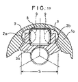
- FIG. 13 Another constant velocity universal joint concerning the conventional technique is known, which is constructed, for example, as illustrated in FIG. 13.
- a pair of track surfaces 2a, 2b which are opposed to one another and which have a circular arc-shaped cross-section, are formed in the axial direction on an inner wall surface of an outer joint member 1a.
- An inner joint member 3a which is disposed between the pair of track surfaces 2a, 2b, is arranged in an internal hollow space of the outer joint member 1a.
- a plurality of ball members 9 are provided rollably along the track surfaces 2a, 2b by the aid of a retainer 8 (see Japanese Patent Publication No. 7-74649).
- the constant velocity universal joint concerning the conventional technique involves the inconvenience that the durability and the vibration characteristics are deteriorated by any dimensional error depending on the machining accuracy for the pair of track surfaces 2a, 2b which are formed on the inner wall surface of the outer joint member 1 in the mutually opposing manner.
- the pair of track surfaces 2a, 2b of the outer joint member 1 on which the ball members 9 roll have a hardness not subjected to plasticization caused by the contact surface pressure generated between the track surfaces 2a, 2b and the ball members 9. For this reason, it is necessary to apply a heat treatment to the pair of track surfaces 2a, 2b, which results in an inconvenience that the production cost becomes expensive.
- a general object of the present invention is to provide a constant velocity universal joint which makes it possible to reduce the induced thrust force so that the driving force may be still more smoothly transmitted from one transmission shaft to the other transmission shaft.
- This constant velocity universal joint which makes it possible to avoid occurrence of vibration in the direction of rotation and beat sound resulting from backlash even when the operating angle between one transmission shaft and the other transmission shaft is increased.
- the spacing distance between a pair of mutually opposing rolling surfaces is not affected by any dimensional error.
- reference numeral 10 indicates a constant velocity universal joint.
- the constant velocity universal joint 10 is basically comprises a cylindrical outer cup (outer member) 12 having an opening and integrally coupled to one end of an unillustrated first shaft, and an inner member 16 fixedly fixedly secured to one end of a second shaft 14 and accommodated in a hole of the outer cup 12.
- each of the guide grooves 18a to 18c comprises a curved section 20 which is formed to have a curved cross section, and sliding surfaces (flat surface sections) 24 which are formed mutually opposingly on both sides of the curved section 20 for sliding slipper members 22a, 22b thereon as described later on.
- the sliding surface 24 is formed to have a flat configuration which extends along the axial direction of the outer cup 12.
- a ring-shaped spider 25 is externally fitted to the second shaft 14.
- Three trunnions 26a (26b, 26c), which expand toward the guide grooves 18a (18b, 18c) respectively and which are spaced apart from each other by 120 degrees about the center of the axis, are formed integrally on an outer circumferential surface of the spider 25.
- An outer surface of each of the trunnions 26a (26b, 26c) facing with the sliding surface 24 is formed to be spherical.
- the pair of slipper members 22a, 22b are formed to make surface-to-surface contact with the trunnion 26a (26b, 26c) and the sliding surface 24 respectively. As shown in FIG.
- one side surface of the slipper member 22a, 22b, which makes surface-to-surface contact with the trunnion 26a (26b, 26c), is composed of a recess 28 having its inner wall surface which is formed to have a spherical configuration corresponding to the spherical surface of the trunnion 26a (26b, 26c).
- the other side surface, which makes surface-to-surface contact with the sliding surface 24, is formed to be a flat surface 30 corresponding to the sliding surface 24.
- the shape of the recess 28 of the slipper member 22a, 22b contacting with the trunnion 26a (26b, 26c) is a spherical surface formed to have a circular arc-shaped cross section (see FIG. 4A).
- the recess 28a is formed to have a substantially v-shaped cross section to make line-to-line contact with the trunnion 26a (26b, 26c) (see FIG. 4B).
- a hole 32 which penetrate through the center of the recess 28 having the substantially v-shaped cross section as described above, may be formed (see FIG. 4C).
- the provision of the hole 32 is advantageous in that the concentration of stress is avoided, and lubricating oil can be easily poured and applied to the sliding surface of the trunnion 26a (26b, 26c) and the slipper member 22a, 22b.
- the slipper member 22a, 22b may be formed to have the disk-shaped configuration as shown in FIG. 3 or a rectangular configuration as shown in FIG. 5, by using a material made of metal or resin.
- the constant velocity universal joint 10 is basically constructed as described above. Next, its operation, function, and effect will be explained.
- the rotary power of the outer cup 12 is transmitted to the slipper members 22a, 22b which make displacement along the guide grooves 18a (18b, 18c), and it is further transmitted to the trunnions 26a (26b, 26c) which make surface-to-surface contact with the slipper members 22a, 22b.
- the second shaft 14, which is engaged with the trunnions 26a (26b, 26c) is rotated.
- the trunnion 26a (26b, 26c), which is formed to have the spherical configuration, makes sliding displacement by predetermined angles in the directions indicated by an arrow C (see FIG. 2) and an arrow D (see FIG. 6) along the recesses 28 of the spherical surfaces formed on one side surfaces of the slipper members 22a, 22b.
- the slipper members 22a, 22b make sliding displacement along the sliding surfaces 24 via the flat surfaces 30 formed on the other side surfaces.
- the slipper members 22a, 22b are provided slidably displaceably in all directions concerning the sliding surfaces 24 including the direction indicated by an arrow E (see FIG. 1) parallel to the axis of the sliding surfaces 24 and the direction indicated by an arrow F (see FIG. 2) perpendicular to the axis. Accordingly, the rotational motion of the first shaft is transmitted to the second shaft 14 without being affected by the angle of inclination of the second shaft 14 with respect to the outer cup 12.
- the pair of slipper members 22a, 22b which are slidably displaceable while making surface-to-surface contact with the trunnions 26a (26b, 26c) and the sliding surfaces 24, are interposed between the trunnions 26a (26b, 26c) and the sliding surfaces 24. Therefore, in the first embodiment, the surface pressure at the sliding section is lowered as compared with the conventional technique which is based on the linear contact with the sliding section. Thus, it is possible to stabilize the lubricating performance without causing any oil film breakage at the sliding section. As a result, it is possible to avoid, for example, occurrence of pits and adhesive wear resulting from lubrication failure.
- induced thrust force refers to the load resulting from frictional resistance generated by the sliding displacement of the slipper members 22a, 22b along the guide grooves 18a to 18c.
- the induced thrust force is rapidly increased in accordance with the increase in the angle of inclination of the second shaft 14.
- the induced thrust force is maintained to be approximately constant even when the angle of inclination is increased. Therefore, in the constant velocity universal joint 10 according to this embodiment, the induced thrust force, which is generated resulting from the frictional resistance, is not increased rapidly even when the angle of inclination of the second shaft 14 with respect to the outer cup 12 is increased. Thus, it is possible to stabilize the induced thrust force.
- a plurality of lubricating grooves 34 which are arranged longitudinally and latitudinally, are formed to make intersection (see FIG. 8A), or lubricating grooves 36, which extend outwardly in a curved configuration, are formed in four directions (see FIG. 8B) on outer surfaces of the trunnions 26a (26b, 26c) which contact with the slipper members 22a, 22b.
- lubricating grooves 34 which are arranged longitudinally and latitudinally, are formed to make intersection (see FIG. 8A), or lubricating grooves 36, which extend outwardly in a curved configuration, are formed in four directions (see FIG. 8B) on outer surfaces of the trunnions 26a (26b, 26c) which contact with the slipper members 22a, 22b.
- the location of the lubricating grooves 34, 36 is not limited to the outer surfaces of the trunnions 26a (26b, 26c).
- the lubricating grooves 34, 36 may be formed on the spherical surfaces of the trunnions 26a (26b, 26c), the recesses 28 of the slipper members 22a, 22b which make surface-to-surface contact with the sliding surfaces 24 of the guide grooves 18a (18b, 18c), and the flat surfaces 30 respectively.
- the lubricating performance may be improved by forming oil sumps such as dimples (not shown) on the outer surfaces of the trunnions 26a (26b, 26c).
- oil sumps such as dimples (not shown)
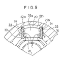
- At least one stripe of lubricating groove 38 which extends substantially in parallel to the axis of the outer cup 12, may be formed on the sliding surface 24 of the guide groove 18a (18b, 18c).
- the sectional configuration of the lubricating groove 38 may be V-shaped, circular arc-shaped, or rectangular.
- the lubricating groove 38 may be provided as a plurality of individuals.
- this embodiment it is enough to provide only the pair of slipper members 22a, 22b, as compared with the conventional technique. Therefore, this embodiment is advantageous in that the number of parts is decreased, and the production cost can be reduced.
Description
- The present invention relates to a constant velocity universal joint according to the pre-characterizing part of
claim 1. The joint is to be used, for example, for a driving force-transmitting section of an automobile. - A universal joint of this type is known from US-A 3,381,497. It has gliding members with recesses of curved sectional shape.
- A constant velocity universal joint has been hitherto used for a driving force-transmitting section of an automobile in order to transmit a rotary power or a torque of a driving shaft to respective axles through a driven shaft.
- A constant velocity universal joint concerning the conventional technique is known, for example, as illustrated in FIG. 11, in which three
track grooves 2 are formed along the axial direction on an inner surface of anouter wheel 1.Leg shafts 4, which protrude in the radial direction, are provided on atripod member 3 which is arranged inside theouter wheel 1. Aspherical roller 6 is fitted rotatably and slidably in the axial direction to an outer circumferential surface of each of theleg shafts 4 via a plurality ofneedle bearings 5. Thespherical roller 6 is allowed to engage with aroller guide surface 7 disposed on both sides of thetrack groove 2. - However, in the case of the constant velocity universal joint concerning the conventional technique as described above, when a high load is applied in a state in which the
tripod member 3 is inclined by a predetermined angle with respect to the axis of theouter wheel 1, then the force to press theroller guide surface 7 by thespherical roller 6, i.e., the surface pressure exerted on theroller guide surface 7 is increased, because each of thespherical rollers 6 linearly contacts with theroller guide surface 7 of thetrack groove 2. As a result, oil film breakage occurs at the contact surface between thespherical roller 6 and theroller guide surface 7, and lubrication failure occurs. Further, the following inconveniences take plate. That is, the lubrication failure causes formation of small holes on the surface of thespherical roller 6, i.e., so-called pits are generated. In other cases, irregularities are formed on the surface of thespherical roller 6, i.e., so-called adhesive wear occurs. - On the other hand, in the case of the constant velocity universal joint concerning the conventional technique as described above, when the
tripod member 3 is inclined by a predetermined angle with respect to the axis of theouter wheel 1, a relationship is given as shown in FIG. 12, in which each of thespherical rollers 6 obliquely intersects theroller guide surface 7 of thecylindrical track groove 2 with each other. In such a state, it is impossible to allow thespherical roller 6 to perform proper rolling motion. - That is, the
spherical roller 6 intends to perform rolling motion in the direction indicated by an arrow A or an arrow B shown in FIG. 11, while thetrack groove 2 is cylindrical and it extends substantially in parallel to the axis of theouter wheel 1. Therefore, thespherical roller 6 is moved while being restricted by thetrack groove 2. As a result, a thrust force in the axial direction is induced by the slippage which is caused between the roller guide surface .7 of thetrack groove 2 and thespherical roller 6. The induced thrust force is increased in proportion to the increase of the angle of inclination of thetripod member 3 with respect to theouter wheel 1. It is feared to be difficult to smoothly transmit the rotary power of the driving shaft to the driven shaft. It is noted that a frictional resistance is generated by the reciprocating motion effected by thespherical roller 6 along theroller guide surface 7. In this context, the induced thrust force refers to a load resulting from the frictional resistance. - In order to solve the problem as described above, a constant velocity universal joint is known, which is disclosed, for example, in Japanese Laid-Open Patent Publication No. 3-168416. In this constant velocity universal joint, three ball grooves are formed in the axial direction at the inside of an outer wheel. Three pairs of balls are held in the respective ball grooves by the aid of holders respectively. A tripod member is incorporated into the inside of the outer wheel. Three leg shafts extending in the radial direction, which are arranged between the adjacent pairs of balls, are provided on the tripod member. Each of the leg shafts is formed with a spherical surface. A ball guide, which is formed with a spherical recess for engaging with the spherical surface, is provided between the spherical surface and the balls.
- However, in the case of the constant velocity universal joint disclosed in Japanese Laid-Open Patent Publication No. 3-168416, when the operating angle between the first shaft provided at the closed end of the outer wheel and the second shaft provided on the tripod member is increased, there is a fear of occurrence of vibration in the direction of rotation and so-called beat sound resulting from backlash. The beat sound described above refers to a sound generated by looseness in the direction of rotation. Further, there is a fear that the following inconveniences may occur. That is, the balls tend to be disengaged from the holder upon assembly, it is difficult to retain the balls in the ball guide, a high technique is required for assembling, the assembling time is prolonged, and the operation efficiency is lowered.
- A three-plane constant velocity joint is disclosed in Japanese Laid-Open Patent Publication No. 6-74243. In this case, an inner joint member is inserted into the inside of an outer joint member, and trunnions are provided on the inner joint member. Each of the trunnions is provided with a plurality of spherical balls. The spherical balls are constructed so that they are rollable along side walls which constitute a longitudinal chamber formed in the outer joint member. The spherical balls are held on the trunnion by the aid of a positioning spring installed to the trunnion.
- However, also in the case of the three-plane constant velocity joint disclosed in Japanese Laid-Open Patent Publication No. 6-74243, when the operating angle between the outer joint member and the inner joint member is increased, there is a fear of occurrence of vibration in the direction of rotation and so-called beat sound resulting from backlash. Further, it is difficult to retain the spherical balls on the trunnion upon assembling. It is feared that the efficiency of the assembling operation is lowered.
- Another constant velocity universal joint concerning the conventional technique is known, which is constructed, for example, as illustrated in FIG. 13. In this case, a pair of
track surfaces joint member 3a, which is disposed between the pair oftrack surfaces ball members 9 are provided rollably along thetrack surfaces - However, in the case of the constant velocity universal joint concerning the conventional technique, when the spacing distance S between the pair of
track surfaces ball members 9 which roll along the pair oftrack surfaces track surfaces ball members 9 and the pair oftrack surfaces track surfaces joint member 1 in the mutually opposing manner. - Further, it is necessary that the pair of
track surfaces outer joint member 1 on which theball members 9 roll have a hardness not subjected to plasticization caused by the contact surface pressure generated between thetrack surfaces ball members 9. For this reason, it is necessary to apply a heat treatment to the pair oftrack surfaces - A general object of the present invention is to provide a constant velocity universal joint which makes it possible to reduce the induced thrust force so that the driving force may be still more smoothly transmitted from one transmission shaft to the other transmission shaft.
- This is achieved by the universal joint having the features of
claim 1. Preferred embodiment are defined by the dependent claim. - This constant velocity universal joint which makes it possible to avoid occurrence of vibration in the direction of rotation and beat sound resulting from backlash even when the operating angle between one transmission shaft and the other transmission shaft is increased.
- It is possible to stabilize lubrication performance and avoid occurrence of pits and adhesive wear.
- It is also possible to shorten the assembling time and improve the operation efficiency by reliably holding ball members upon assembling without any disengagement of the ball members.
- Specifically, the spacing distance between a pair of mutually opposing rolling surfaces is not affected by any dimensional error.
- It is possible to reduce the production cost by omitting the heat treatment step which would be otherwise required for rolling surfaces of an outer member.
- The above and other objects, features, and advantages of the present invention will become more apparent from the following description when taken in conjunction with the accompanying drawings in which a preferred embodiment of the present invention is shown by way of illustrative example.
-
- FIG. 1 shows a longitudinal sectional view taken along an axial direction of a constant velocity universal joint.
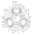
- FIG. 2 shows a sectional view taken along a line II-II shown in FIG. 1.
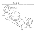
- FIG. 3 shows a perspective view illustrating a trunnion and a pair of slipper members engaging with the trunnion.
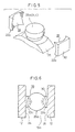
- FIG. 4A to 4C show longitudinal sectional views, wherein figs. 4B and 4C illustrate embodiments of the slipper member shown in FIG. 3 according to the invention.
- FIG. 5 shows a perspective view illustrating a modified embodiment of the slipper member shown in FIG. 3.
- FIG. 6 shows a sectional view taken along a line VI-VI shown in FIG. 2.
- FIGs. 7A and 7B illustrate the relationship between the angle of inclination of the second shaft and the induced thrust force.
- FIGs. 8A and 8B illustrate shapes of lubricating grooves formed on outer surfaces of the trunnions respectively.
- FIG. 9 shows a cross-sectional view, with partial omission, illustrating lubricating grooves formed on sliding surfaces of a guide groove.
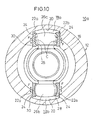
- FIG. 10 shows a cross-sectional view illustrating application of the constant velocity universal joint shown in FIG. 2 to a bipod type.
- FIG. 11 shows a partial sectional side view illustrating a constant velocity universal joint concerning the conventional technique.
- FIG. 12 shows a magnified perspective view illustrating a state in which a spherical roller used for the constant velocity universal joint shown in FIG. 11 is inclined by a predetermined angle with respect to a roller guide groove.
- FIG. 13 shows a partial sectional view illustrating a constant velocity universal joint concerning the conventional technique
-
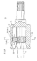
- In FIGs. 1 and 2,
reference numeral 10 indicates a constant velocity universal joint. The constant velocityuniversal joint 10 is basically comprises a cylindrical outer cup (outer member) 12 having an opening and integrally coupled to one end of an unillustrated first shaft, and aninner member 16 fixedly fixedly secured to one end of asecond shaft 14 and accommodated in a hole of theouter cup 12. - As shown in FIG. 2, three
guide grooves 18a to 18c, which extend along the axial direction and which are spaced apart from each other by 120 degrees about the center of the axis, are formed on an inner circumferential surface of theouter cup 12. Each of theguide grooves 18a to 18c comprises acurved section 20 which is formed to have a curved cross section, and sliding surfaces (flat surface sections) 24 which are formed mutually opposingly on both sides of thecurved section 20 for slidingslipper members surface 24 is formed to have a flat configuration which extends along the axial direction of theouter cup 12. - A ring-shaped
spider 25 is externally fitted to thesecond shaft 14. Threetrunnions 26a (26b, 26c), which expand toward theguide grooves 18a (18b, 18c) respectively and which are spaced apart from each other by 120 degrees about the center of the axis, are formed integrally on an outer circumferential surface of thespider 25. An outer surface of each of thetrunnions 26a (26b, 26c) facing with the slidingsurface 24 is formed to be spherical. - A pair of slipper members (gliding members) 22a, 22b, each of which has an identical shape, are interposed between the
trunnion 26a (26b, 26c) and the slidingsurface 24. The pair ofslipper members trunnion 26a (26b, 26c) and the slidingsurface 24 respectively. As shown in FIG. 3, one side surface of theslipper member trunnion 26a (26b, 26c), is composed of arecess 28 having its inner wall surface which is formed to have a spherical configuration corresponding to the spherical surface of thetrunnion 26a (26b, 26c). The other side surface, which makes surface-to-surface contact with the slidingsurface 24, is formed to be aflat surface 30 corresponding to the slidingsurface 24. - Conventionally, the shape of the
recess 28 of theslipper member trunnion 26a (26b, 26c) is a spherical surface formed to have a circular arc-shaped cross section (see FIG. 4A). According to the present invention, therecess 28a is formed to have a substantially v-shaped cross section to make line-to-line contact with thetrunnion 26a (26b, 26c) (see FIG. 4B). Alternatively, ahole 32, which penetrate through the center of therecess 28 having the substantially v-shaped cross section as described above, may be formed (see FIG. 4C). The provision of thehole 32 is advantageous in that the concentration of stress is avoided, and lubricating oil can be easily poured and applied to the sliding surface of thetrunnion 26a (26b, 26c) and theslipper member - Preferably, the
slipper member - The constant velocity universal joint 10 according to this embodiment of the present invention is basically constructed as described above. Next, its operation, function, and effect will be explained.
- When the unillustrated first shaft is rotated, then its rotary power is transmitted to the
inner member 16 via theouter cup 12, and thesecond shaft 14 is rotated in a predetermined direction by the aid of thetrunnions 26a to 26c formed to be spherical. - That is, the rotary power of the
outer cup 12 is transmitted to theslipper members guide grooves 18a (18b, 18c), and it is further transmitted to thetrunnions 26a (26b, 26c) which make surface-to-surface contact with theslipper members second shaft 14, which is engaged with thetrunnions 26a (26b, 26c), is rotated. - During this process, when the
second shaft 14 is inclined by a predetermined angle with respect to theouter cup 12 having the first shaft, thetrunnion 26a (26b, 26c), which is formed to have the spherical configuration, makes sliding displacement by predetermined angles in the directions indicated by an arrow C (see FIG. 2) and an arrow D (see FIG. 6) along therecesses 28 of the spherical surfaces formed on one side surfaces of theslipper members trunnion 26a (26b, 26c), theslipper members surfaces 24 via theflat surfaces 30 formed on the other side surfaces. In this embodiment, theslipper members surfaces 24 including the direction indicated by an arrow E (see FIG. 1) parallel to the axis of the slidingsurfaces 24 and the direction indicated by an arrow F (see FIG. 2) perpendicular to the axis. Accordingly, the rotational motion of the first shaft is transmitted to thesecond shaft 14 without being affected by the angle of inclination of thesecond shaft 14 with respect to theouter cup 12. - As described above, in this embodiment, the pair of
slipper members trunnions 26a (26b, 26c) and the slidingsurfaces 24, are interposed between thetrunnions 26a (26b, 26c) and the sliding surfaces 24. Therefore, in the first embodiment, the surface pressure at the sliding section is lowered as compared with the conventional technique which is based on the linear contact with the sliding section. Thus, it is possible to stabilize the lubricating performance without causing any oil film breakage at the sliding section. As a result, it is possible to avoid, for example, occurrence of pits and adhesive wear resulting from lubrication failure. - The relationship between the induced thrust force and the relative angle of inclination of the
second shaft 14 with respect to the first shaft is shown in FIGs. 7A and 7B. The term "induced thrust force" described above refers to the load resulting from frictional resistance generated by the sliding displacement of theslipper members guide grooves 18a to 18c. - As shown in FIG. 7B, in the case of a constant velocity universal joint concerning the conventional technique '(straight line G), the induced thrust force is rapidly increased in accordance with the increase in the angle of inclination of the
second shaft 14. On the contrary, as shown in FIG. 7A, in the case of the constant velocity universal joint 10 according to the first embodiment (straight line H), the induced thrust force is maintained to be approximately constant even when the angle of inclination is increased. Therefore, in the constant velocity universal joint 10 according to this embodiment, the induced thrust force, which is generated resulting from the frictional resistance, is not increased rapidly even when the angle of inclination of thesecond shaft 14 with respect to theouter cup 12 is increased. Thus, it is possible to stabilize the induced thrust force. - In this embodiment, for example, a plurality of
lubricating grooves 34, which are arranged longitudinally and latitudinally, are formed to make intersection (see FIG. 8A), or lubricatinggrooves 36, which extend outwardly in a curved configuration, are formed in four directions (see FIG. 8B) on outer surfaces of thetrunnions 26a (26b, 26c) which contact with theslipper members trunnions 26a (26b, 26c) and theslipper members lubricating grooves trunnions 26a (26b, 26c). Thelubricating grooves trunnions 26a (26b, 26c), therecesses 28 of theslipper members surfaces 24 of theguide grooves 18a (18b, 18c), and theflat surfaces 30 respectively. Further, the lubricating performance may be improved by forming oil sumps such as dimples (not shown) on the outer surfaces of thetrunnions 26a (26b, 26c). In addition, as shown in FIG. 9, at least one stripe of lubricatinggroove 38, which extends substantially in parallel to the axis of theouter cup 12, may be formed on the slidingsurface 24 of theguide groove 18a (18b, 18c). The sectional configuration of the lubricatinggroove 38 may be V-shaped, circular arc-shaped, or rectangular. The lubricatinggroove 38 may be provided as a plurality of individuals. - Further, it is possible to reduce the coefficient of friction by applying a coating treatment to any one of or both of the surfaces of the
trunnions 26a (26b, 26c) and theslipper members - In this embodiment, it is enough to provide only the pair of
slipper members - The embodiment has been explained with reference to the tripod type constant velocity universal joint 10 provided with the three
trunnions 26a (26b, 26c). However, the present invention is not limited thereto. It is a matter of course that the present invention can be applied to a constant velocity universal joint 10a of the bipod type as shown in FIG. 10.
Claims (5)
- A constant velocity universal joint having a cylindrical outer member (12) which is provided on its inner circumferential surface with a plurality of guide grooves (18a to 18c) spaced apart from each other by a predetermined spacing distance and extending along an axial direction and which is coupled to one transmission shaft, and an inner member (16) which is inserted into an open internal hollow space of said outer member (12) and which is coupled to the other transmission shaft, said constant velocity universal joint comprising:a plurality of trunnions (26a to 26c) which are formed to be spherical and which expand toward said guide grooves (18a to 18c);flat surface sections (24) which are formed on mutually opposing side surfaces of said guide grooves (18a to 18c) and which extend in a flat surface configuration along said axial direction of said outer member (12); andpairs of gliding members (22a, 22b) having an identical shape each of which is interposed between said flat surface section (24) and said trunnion (26a to 26c), each of which has one side surface formed with a recess (28a) to make contact with a spherical surface of said trunnion (26a to 26c), and each of which has the other side surface formed with a flat surface (30) to make contact with said flat surface section (24), wherein:said pairs of gliding members (22a, 22b) are provided slidably with respect to said flat surface sections (24) of said guide grooves (18a to 18c) and said spherical surfaces of said trunnions (26a to 26c) characterized in that said recess (28a) of said gliding member (22a, 22b) has a sectional shape formed to be a substantially v-shaped sectional configuration involving linear inclination at a predetermined angle from ends to a center.
- The constant velocity universal joint according to claim 1, wherein a penetrating hole (32) is formed through a central portion of said recess (28a) of said gliding member (22a, 22b).
- The constant velocity universal joint according to claim 1, wherein lubricating grooves (34, 36) are formed on said spherical surface of said trunnion (26a to 26c) or on said recess (28a) of said gliding member (22a, 22b) contacting with said spherical surface.
- The constant velocity universal joint according to claim 1, wherein lubricating grooves (34, 36) are formed on said flat surface (30) of said gliding member (22a, 22b) contacting with said flat surface section (24) of said guide groove (18a to 18c).
- The constant velocity universal joint according to claim 1, wherein at least one or more stripes of lubricating grooves (38) are formed on said flat surface section (24) of said guide groove (18a to 18c) substantially in parallel to said axial direction of said outer member (12).
Priority Applications (1)
| Application Number | Priority Date | Filing Date | Title |
|---|---|---|---|
| EP01129020A EP1188944A3 (en) | 1997-02-10 | 1998-02-09 | Constant velocity universal joint |
Applications Claiming Priority (15)
| Application Number | Priority Date | Filing Date | Title |
|---|---|---|---|
| JP2699497A JPH10220488A (en) | 1997-02-10 | 1997-02-10 | Constant velocity joint |
| JP2699397 | 1997-02-10 | ||
| JP26993/97 | 1997-02-10 | ||
| JP2699397A JPH10220487A (en) | 1997-02-10 | 1997-02-10 | Constant velocity joint |
| JP26994/97 | 1997-02-10 | ||
| JP2699497 | 1997-02-10 | ||
| JP4626897 | 1997-02-28 | ||
| JP46277/97 | 1997-02-28 | ||
| JP4627797 | 1997-02-28 | ||
| JP4627797A JPH10238550A (en) | 1997-02-28 | 1997-02-28 | Constant velocity universal joint |
| JP04626897A JP3894995B2 (en) | 1997-02-28 | 1997-02-28 | Constant velocity joint |
| JP46268/97 | 1997-02-28 | ||
| JP12237797A JPH10311344A (en) | 1997-05-13 | 1997-05-13 | Uniform joint |
| JP122377/97 | 1997-05-13 | ||
| JP12237797 | 1997-05-13 |
Related Child Applications (1)
| Application Number | Title | Priority Date | Filing Date |
|---|---|---|---|
| EP01129020A Division EP1188944A3 (en) | 1997-02-10 | 1998-02-09 | Constant velocity universal joint |
Publications (2)
| Publication Number | Publication Date |
|---|---|
| EP0861992A1 EP0861992A1 (en) | 1998-09-02 |
| EP0861992B1 true EP0861992B1 (en) | 2002-09-04 |
Family
ID=27520885
Family Applications (2)
| Application Number | Title | Priority Date | Filing Date |
|---|---|---|---|
| EP01129020A Withdrawn EP1188944A3 (en) | 1997-02-10 | 1998-02-09 | Constant velocity universal joint |
| EP98102222A Expired - Lifetime EP0861992B1 (en) | 1997-02-10 | 1998-02-09 | Constant velocity universal joint |
Family Applications Before (1)
| Application Number | Title | Priority Date | Filing Date |
|---|---|---|---|
| EP01129020A Withdrawn EP1188944A3 (en) | 1997-02-10 | 1998-02-09 | Constant velocity universal joint |
Country Status (10)
| Country | Link |
|---|---|
| US (2) | US6165075A (en) |
| EP (2) | EP1188944A3 (en) |
| KR (1) | KR100378023B1 (en) |
| CN (1) | CN1128299C (en) |
| CA (1) | CA2229122C (en) |
| DE (1) | DE69807543T2 (en) |
| ID (1) | ID20035A (en) |
| MX (1) | MXPA98001078A (en) |
| MY (1) | MY125713A (en) |
| TW (1) | TW359728B (en) |
Families Citing this family (28)
| Publication number | Priority date | Publication date | Assignee | Title |
|---|---|---|---|---|
| US6074303A (en) * | 1998-12-04 | 2000-06-13 | General Motors Corporation | Constant velocity universal joint |
| DE60107387T2 (en) * | 2000-02-04 | 2005-12-29 | Gkn Technology Ltd., Wolverhampton | TRIPODESGLEICHLAUFGELENK |
| JP4015822B2 (en) * | 2001-04-25 | 2007-11-28 | Ntn株式会社 | Constant velocity universal joint |
| EP1286072B1 (en) | 2001-08-23 | 2005-04-27 | DaimlerChrysler AG | Tripod joint |
| JP2003065350A (en) * | 2001-08-28 | 2003-03-05 | Ntn Corp | Tripod type constant velocity universal coupling |
| JP3894760B2 (en) * | 2001-09-26 | 2007-03-22 | Ntn株式会社 | Constant velocity universal joint |
| CN1277061C (en) | 2001-10-26 | 2006-09-27 | Ntn株式会社 | Triangle constant-speed universal connect |
| US7004842B2 (en) | 2003-01-31 | 2006-02-28 | Torque-Traction Technologies, Inc. | Compound driveshaft assembly with constant velocity joint |
| DE10315884B4 (en) * | 2003-04-08 | 2014-03-20 | Daimler Ag | Longitudinally installed four-wheel drive train |
| US7877043B2 (en) * | 2004-09-22 | 2011-01-25 | Ntn Corporation | Constant-velocity joint and image-forming device |
| US7289752B2 (en) * | 2004-09-24 | 2007-10-30 | Ntn Corporation | Tripod type constant-velocity joint and image-forming device |
| DE112005003687B4 (en) * | 2005-10-06 | 2013-05-29 | Gkn Driveline International Gmbh | Tripod joint with spring-supported roller arrangements |
| US7878914B2 (en) * | 2007-05-17 | 2011-02-01 | Hyundai Wia Corporation | Constant velocity joint of tripod type |
| DE112007003668B4 (en) * | 2007-10-23 | 2015-09-17 | Gkn Driveline International Gmbh | tripod |
| EP2623809B1 (en) * | 2008-06-24 | 2016-05-18 | Jtekt Corporation | Sliding type tripod constant velocity joint |
| DE102010015133A1 (en) * | 2010-04-16 | 2011-10-20 | Volkswagen Ag | tripod |
| DE102010053391A1 (en) * | 2010-12-03 | 2012-06-06 | Volkswagen Ag | Tripod roller made of thin-walled material |
| DE102011009219A1 (en) * | 2011-01-22 | 2012-07-26 | Volkswagen Ag | Tripod joint for transferring torque from driven end on bearing end shaft, has inner joint part and outer joint part, where rolling element track is designed in running direction of rolling bodies |
| DE102011103247A1 (en) * | 2011-06-03 | 2012-12-06 | Volkswagen Aktiengesellschaft | Rolling element of a tripod joint and tripod joint, comprising such a rolling element |
| DE102011111815A1 (en) * | 2011-08-27 | 2013-02-28 | Volkswagen Aktiengesellschaft | Tripod joint for transmission of torque between rotating axles, has securing stop arranged in such manner so that contact of cage with wall surfaces of joint outer portion is prevented during movement of cage relative to outer portion |
| US9180736B2 (en) | 2014-03-13 | 2015-11-10 | Arrma Durango Ltd | Wheel axle for a constant-velocity drive type driveshaft joint with adjustable axial positions |
| CA2876686C (en) | 2014-12-24 | 2021-01-19 | Honey Bee Manufacturing Ltd. | Reel system |
| WO2016101059A1 (en) * | 2014-12-24 | 2016-06-30 | Honey Bee Manufacturing Ltd. | Reel system |
| CN105443595A (en) * | 2015-12-22 | 2016-03-30 | 万向钱潮重庆汽车部件有限公司 | End recessed three-groove shell |
| JP6719912B2 (en) * | 2016-01-21 | 2020-07-08 | 昌弘 町田 | Rotation transmission mechanism |
| KR101759904B1 (en) * | 2016-12-21 | 2017-07-20 | 이래오토모티브시스템 주식회사 | Tripod constant velocity joint |
| CN107571687B (en) * | 2017-07-27 | 2024-01-19 | 北京猎户星空科技有限公司 | Omnidirectional ball wheel |
| CN111749990A (en) * | 2020-07-01 | 2020-10-09 | 上海电动工具研究所(集团)有限公司 | Torsion coupling tripping structure |
Family Cites Families (35)
| Publication number | Priority date | Publication date | Assignee | Title |
|---|---|---|---|---|
| US1582997A (en) * | 1924-05-02 | 1926-05-04 | Frank R Mcgee | Flexible coupling |
| FR853688A (en) * | 1938-05-04 | 1940-03-26 | Parsons Marine Steam Turbine | Improvements to mechanical couplings |
| US2760359A (en) * | 1952-04-24 | 1956-08-28 | Wildhaber Ernest | Yielding roller, especially for universal joints |
| FR1228149A (en) * | 1959-03-02 | 1960-08-26 | Glaenzer Spicer Sa | Further training in sliding couplings |
| US3381497A (en) * | 1966-10-10 | 1968-05-07 | Borg Warner | Universal joint |
| FR2172580A5 (en) * | 1972-02-18 | 1973-09-28 | Glaenzer Spicer Sa | |
| JPS5354644A (en) * | 1976-10-27 | 1978-05-18 | Hitachi Constr Mach Co Ltd | Uniform velocity universal joint |
| JPS5376253A (en) * | 1976-12-20 | 1978-07-06 | Toyota Motor Corp | Universal coupling |
| JPS54132046A (en) * | 1978-04-05 | 1979-10-13 | Honda Motor Co Ltd | Slide type uniform velocity universal joint |
| DE3163329D1 (en) * | 1980-02-12 | 1984-06-07 | Citroen Sa | Universal joints |
| FR2580751B1 (en) * | 1985-04-19 | 1989-12-08 | Glaenzer Spicer Sa | SLIDING LOCAL JOINT, PARTICULARLY FOR VEHICLE SIDE TRANSMISSION |
| JPH0322577Y2 (en) * | 1985-09-17 | 1991-05-16 | ||
| JPS62233522A (en) * | 1986-04-02 | 1987-10-13 | Ntn Toyo Bearing Co Ltd | Equal velocity universal joint |
| FR2607883B1 (en) * | 1986-12-05 | 1991-05-17 | Orain Michel | TELESCOPIC TRANSMISSION JOINT, PARTICULARLY FOR VEHICLE |
| FR2608236B1 (en) * | 1986-12-16 | 1990-12-14 | Glaenzer Spicer Sa | LOAD REVERSE DAMPING TRANSMISSION JOINT, PARTICULARLY FOR VEHICLES |
| DE3905566C1 (en) * | 1989-02-23 | 1990-03-01 | Loehr & Bromkamp Gmbh, 6050 Offenbach, De | |
| JP2763624B2 (en) * | 1989-10-31 | 1998-06-11 | エヌティエヌ株式会社 | Constant velocity joint |
| FR2654782A1 (en) * | 1989-11-17 | 1991-05-24 | Glaenzer Spicer Sa | JOINT OF TRANSMISSION ARTICULATED TELESCOPIC, PARTICULARLY FOR THE AUTOMOBILE. |
| JPH03168416A (en) | 1989-11-27 | 1991-07-22 | Ntn Corp | Constant speed joint |
| FR2658676B1 (en) | 1990-02-16 | 1992-06-12 | France Etat | QUANTIFICATION DEVICE WITH VARIABLE DIGITAL CODING RATE. |
| WO1991016549A1 (en) * | 1990-04-16 | 1991-10-31 | Gkn Automotive, Inc. | A telescopic triplan universal joint |
| FR2667120A1 (en) * | 1990-09-21 | 1992-03-27 | Glaenzer Spicer Sa | TELESCOPIC JOINT TRANSMISSION JOINT AND METHODS OF MAKING A SINGLE TRACK ELEMENT, IN PARTICULAR FOR SUCH A JOINT. |
| DE4142359C2 (en) * | 1991-05-31 | 1996-12-12 | Ntn Toyo Bearing Co Ltd | Outer ring for a vibration-protected homokinetic joint |
| DE4142214C2 (en) * | 1991-12-20 | 1997-07-03 | Loehr & Bromkamp Gmbh | Tripod joint |
| US5254038A (en) * | 1992-01-23 | 1993-10-19 | Gkn Automotive, Inc. | Ball triplan constant velocity joint centering spring |
| DE4205654C1 (en) * | 1992-02-25 | 1993-07-29 | Gkn Automotive Ag, 5200 Siegburg, De | Synchronised rotary joint for motor vehicle drives - has three circumferentially spaced elastic moulded bodies connecting inner and outer parts |
| FR2694056B1 (en) * | 1992-07-24 | 1994-12-16 | Glaenzer Spicer Sa | Articulated sliding joint. |
| US5348512A (en) * | 1992-11-12 | 1994-09-20 | Ina Bearing Company, Inc. | Friction reduced constant velocity universal joint |
| JP3184647B2 (en) * | 1992-12-25 | 2001-07-09 | エヌティエヌ株式会社 | Constant velocity universal joint |
| JPH0835527A (en) * | 1994-07-25 | 1996-02-06 | Ntn Corp | Constant velocity universal joint |
| US5827121A (en) * | 1994-12-23 | 1998-10-27 | Ntn Corporation | Homokinetic universal joint having straight recirculating ball paths in flat side surfaces of track grooves |
| FR2729194B1 (en) * | 1995-01-11 | 1997-04-04 | Gkn Glaenzer Spicer | SLIDING TRANSMISSION JOINT, PARTICULARLY FOR MOTOR VEHICLE |
| FR2729193B1 (en) * | 1995-01-11 | 1997-04-04 | Gkn Glaenzer Spicer | IMPROVED SLIDING TRANSMISSION JOINT |
| FR2730773B1 (en) * | 1995-02-17 | 1997-04-30 | Guimbretiere Pierre | SLIDING TRANSMISSION JOINT, ESPECIALLY TRIPOD |
| DE19544174C2 (en) * | 1995-11-14 | 2003-04-17 | Ina Schaeffler Kg | Tripod constant velocity joint |
-
1998
- 1998-02-07 MY MYPI98000502A patent/MY125713A/en unknown
- 1998-02-09 CA CA002229122A patent/CA2229122C/en not_active Expired - Fee Related
- 1998-02-09 EP EP01129020A patent/EP1188944A3/en not_active Withdrawn
- 1998-02-09 MX MXPA98001078A patent/MXPA98001078A/en not_active IP Right Cessation
- 1998-02-09 EP EP98102222A patent/EP0861992B1/en not_active Expired - Lifetime
- 1998-02-09 TW TW087101697A patent/TW359728B/en not_active IP Right Cessation
- 1998-02-09 DE DE69807543T patent/DE69807543T2/en not_active Expired - Fee Related
- 1998-02-10 ID IDP980171A patent/ID20035A/en unknown
- 1998-02-10 US US09/021,442 patent/US6165075A/en not_active Expired - Fee Related
- 1998-02-10 KR KR10-1998-0003843A patent/KR100378023B1/en not_active IP Right Cessation
- 1998-02-10 CN CN98104092A patent/CN1128299C/en not_active Expired - Fee Related
-
2000
- 2000-07-28 US US09/628,008 patent/US6435972B1/en not_active Expired - Fee Related
Also Published As
| Publication number | Publication date |
|---|---|
| EP0861992A1 (en) | 1998-09-02 |
| EP1188944A2 (en) | 2002-03-20 |
| CN1191282A (en) | 1998-08-26 |
| US6165075A (en) | 2000-12-26 |
| CA2229122C (en) | 2002-07-02 |
| US6435972B1 (en) | 2002-08-20 |
| KR100378023B1 (en) | 2003-10-04 |
| DE69807543D1 (en) | 2002-10-10 |
| MXPA98001078A (en) | 2004-01-21 |
| EP1188944A3 (en) | 2006-05-10 |
| ID20035A (en) | 1998-09-17 |
| DE69807543T2 (en) | 2003-01-16 |
| MY125713A (en) | 2006-08-30 |
| CN1128299C (en) | 2003-11-19 |
| KR19980071229A (en) | 1998-10-26 |
| CA2229122A1 (en) | 1998-08-10 |
| TW359728B (en) | 1999-06-01 |
Similar Documents
| Publication | Publication Date | Title |
|---|---|---|
| EP0861992B1 (en) | Constant velocity universal joint | |
| US4684356A (en) | Roller bearing assemblies for a homokinetic universal joint | |
| US4773890A (en) | Slidable-type homokinetic (universal) tripod joint | |
| US4167860A (en) | Universal joint | |
| JPH0310808B2 (en) | ||
| CA2197403C (en) | Constant velocity universal joint | |
| EP1327083B1 (en) | Constant velocity joint of tripod type | |
| US8535167B2 (en) | Constant velocity joint of tripod type | |
| US7819752B2 (en) | Constant velocity joint of tripod type | |
| EP1505308B1 (en) | Constant velocity universal joint | |
| KR20020013754A (en) | Tripod type constant velocity universal joint | |
| US8608578B2 (en) | Constant velocity joint of tripod type | |
| EP0244064B1 (en) | Telescopic tripot universal joint | |
| EP1489323A2 (en) | Constant velocity universal joint | |
| US7878914B2 (en) | Constant velocity joint of tripod type | |
| US20060247090A1 (en) | Toroidal type continuously variable transmission | |
| KR101203779B1 (en) | constant velocity joint of tripod type | |
| US20230349450A1 (en) | Toroidal continuously variable transmission | |
| US6796923B2 (en) | Toroidal-type continuously variable transmission | |
| JP2023032201A (en) | Tripod type constant velocity universal joint | |
| JPH0349301Y2 (en) | ||
| JP2000345982A (en) | Turning joint | |
| CN115727067A (en) | Sliding type constant velocity universal joint | |
| JPWO2018174099A1 (en) | Pressing device for toroidal continuously variable transmission | |
| JPH10220487A (en) | Constant velocity joint |
Legal Events
| Date | Code | Title | Description |
|---|---|---|---|
| PUAI | Public reference made under article 153(3) epc to a published international application that has entered the european phase |
Free format text: ORIGINAL CODE: 0009012 |
|
| AK | Designated contracting states |
Kind code of ref document: A1 Designated state(s): DE FR GB |
|
| AX | Request for extension of the european patent |
Free format text: AL;LT;LV;MK;RO;SI |
|
| 17P | Request for examination filed |
Effective date: 19990114 |
|
| AKX | Designation fees paid |
Free format text: DE FR GB |
|
| RBV | Designated contracting states (corrected) |
Designated state(s): DE FR GB |
|
| 17Q | First examination report despatched |
Effective date: 20010712 |
|
| GRAG | Despatch of communication of intention to grant |
Free format text: ORIGINAL CODE: EPIDOS AGRA |
|
| GRAG | Despatch of communication of intention to grant |
Free format text: ORIGINAL CODE: EPIDOS AGRA |
|
| GRAH | Despatch of communication of intention to grant a patent |
Free format text: ORIGINAL CODE: EPIDOS IGRA |
|
| GRAH | Despatch of communication of intention to grant a patent |
Free format text: ORIGINAL CODE: EPIDOS IGRA |
|
| GRAA | (expected) grant |
Free format text: ORIGINAL CODE: 0009210 |
|
| AK | Designated contracting states |
Kind code of ref document: B1 Designated state(s): DE FR GB |
|
| REG | Reference to a national code |
Ref country code: GB Ref legal event code: FG4D |
|
| REF | Corresponds to: |
Ref document number: 69807543 Country of ref document: DE Date of ref document: 20021010 |
|
| ET | Fr: translation filed | ||
| PLBE | No opposition filed within time limit |
Free format text: ORIGINAL CODE: 0009261 |
|
| STAA | Information on the status of an ep patent application or granted ep patent |
Free format text: STATUS: NO OPPOSITION FILED WITHIN TIME LIMIT |
|
| 26N | No opposition filed |
Effective date: 20030605 |
|
| PGFP | Annual fee paid to national office [announced via postgrant information from national office to epo] |
Ref country code: DE Payment date: 20070201 Year of fee payment: 10 |
|
| PGFP | Annual fee paid to national office [announced via postgrant information from national office to epo] |
Ref country code: GB Payment date: 20070207 Year of fee payment: 10 |
|
| PGFP | Annual fee paid to national office [announced via postgrant information from national office to epo] |
Ref country code: FR Payment date: 20070208 Year of fee payment: 10 |
|
| GBPC | Gb: european patent ceased through non-payment of renewal fee |
Effective date: 20080209 |
|
| REG | Reference to a national code |
Ref country code: FR Ref legal event code: ST Effective date: 20081031 |
|
| PG25 | Lapsed in a contracting state [announced via postgrant information from national office to epo] |
Ref country code: DE Free format text: LAPSE BECAUSE OF NON-PAYMENT OF DUE FEES Effective date: 20080902 |
|
| PG25 | Lapsed in a contracting state [announced via postgrant information from national office to epo] |
Ref country code: FR Free format text: LAPSE BECAUSE OF NON-PAYMENT OF DUE FEES Effective date: 20080229 |
|
| PG25 | Lapsed in a contracting state [announced via postgrant information from national office to epo] |
Ref country code: GB Free format text: LAPSE BECAUSE OF NON-PAYMENT OF DUE FEES Effective date: 20080209 |