EP0860907A2 - Female wet connector - Google Patents
Female wet connector Download PDFInfo
- Publication number
- EP0860907A2 EP0860907A2 EP98400320A EP98400320A EP0860907A2 EP 0860907 A2 EP0860907 A2 EP 0860907A2 EP 98400320 A EP98400320 A EP 98400320A EP 98400320 A EP98400320 A EP 98400320A EP 0860907 A2 EP0860907 A2 EP 0860907A2
- Authority
- EP
- European Patent Office
- Prior art keywords
- connector
- female
- housing
- female electrical
- cable
- Prior art date
- Legal status (The legal status is an assumption and is not a legal conclusion. Google has not performed a legal analysis and makes no representation as to the accuracy of the status listed.)
- Granted
Links
- 239000012212 insulator Substances 0.000 claims abstract description 26
- 238000004891 communication Methods 0.000 claims abstract description 10
- 239000000463 material Substances 0.000 claims abstract description 8
- 238000000034 method Methods 0.000 claims abstract description 8
- 239000004020 conductor Substances 0.000 claims description 8
- 229910000679 solder Inorganic materials 0.000 claims description 6
- 238000003754 machining Methods 0.000 claims description 4
- 239000003921 oil Substances 0.000 description 20
- 239000012530 fluid Substances 0.000 description 17
- 238000010276 construction Methods 0.000 description 7
- 230000008878 coupling Effects 0.000 description 7
- 238000010168 coupling process Methods 0.000 description 7
- 238000005859 coupling reaction Methods 0.000 description 7
- 238000005553 drilling Methods 0.000 description 7
- 238000005086 pumping Methods 0.000 description 6
- 229920001971 elastomer Polymers 0.000 description 4
- 239000000806 elastomer Substances 0.000 description 4
- NBVXSUQYWXRMNV-UHFFFAOYSA-N fluoromethane Chemical compound FC NBVXSUQYWXRMNV-UHFFFAOYSA-N 0.000 description 4
- 229920002545 silicone oil Polymers 0.000 description 4
- 239000004519 grease Substances 0.000 description 3
- 230000001050 lubricating effect Effects 0.000 description 3
- 239000003129 oil well Substances 0.000 description 3
- 239000012858 resilient material Substances 0.000 description 3
- 238000005452 bending Methods 0.000 description 2
- DMFGNRRURHSENX-UHFFFAOYSA-N beryllium copper Chemical compound [Be].[Cu] DMFGNRRURHSENX-UHFFFAOYSA-N 0.000 description 2
- -1 brass or aluminum Chemical class 0.000 description 2
- 238000009434 installation Methods 0.000 description 2
- 229910001369 Brass Inorganic materials 0.000 description 1
- 229920002449 FKM Polymers 0.000 description 1
- 238000005299 abrasion Methods 0.000 description 1
- DHKHKXVYLBGOIT-UHFFFAOYSA-N acetaldehyde Diethyl Acetal Natural products CCOC(C)OCC DHKHKXVYLBGOIT-UHFFFAOYSA-N 0.000 description 1
- 125000002777 acetyl group Chemical class [H]C([H])([H])C(*)=O 0.000 description 1
- 229910052782 aluminium Inorganic materials 0.000 description 1
- XAGFODPZIPBFFR-UHFFFAOYSA-N aluminium Chemical compound [Al] XAGFODPZIPBFFR-UHFFFAOYSA-N 0.000 description 1
- 230000003466 anti-cipated effect Effects 0.000 description 1
- 230000004888 barrier function Effects 0.000 description 1
- 230000000903 blocking effect Effects 0.000 description 1
- 239000010951 brass Substances 0.000 description 1
- 239000003638 chemical reducing agent Substances 0.000 description 1
- 238000005520 cutting process Methods 0.000 description 1
- 238000013480 data collection Methods 0.000 description 1
- 239000012777 electrically insulating material Substances 0.000 description 1
- 238000005429 filling process Methods 0.000 description 1
- PCHJSUWPFVWCPO-UHFFFAOYSA-N gold Chemical compound [Au] PCHJSUWPFVWCPO-UHFFFAOYSA-N 0.000 description 1
- 239000010931 gold Substances 0.000 description 1
- 229910052737 gold Inorganic materials 0.000 description 1
- 230000005484 gravity Effects 0.000 description 1
- 229920001519 homopolymer Polymers 0.000 description 1
- 238000002347 injection Methods 0.000 description 1
- 239000007924 injection Substances 0.000 description 1
- 238000009413 insulation Methods 0.000 description 1
- 230000002452 interceptive effect Effects 0.000 description 1
- 238000005304 joining Methods 0.000 description 1
- 239000007788 liquid Substances 0.000 description 1
- 238000012423 maintenance Methods 0.000 description 1
- 238000004519 manufacturing process Methods 0.000 description 1
- 230000013011 mating Effects 0.000 description 1
- 229910052751 metal Inorganic materials 0.000 description 1
- 239000002184 metal Substances 0.000 description 1
- 150000002739 metals Chemical class 0.000 description 1
- 238000003032 molecular docking Methods 0.000 description 1
- 239000010705 motor oil Substances 0.000 description 1
- 239000004033 plastic Substances 0.000 description 1
- 229920003023 plastic Polymers 0.000 description 1
- 238000007747 plating Methods 0.000 description 1
- 229920006260 polyaryletherketone Polymers 0.000 description 1
- 229920002530 polyetherether ketone Polymers 0.000 description 1
- 229920001296 polysiloxane Polymers 0.000 description 1
- 229920001343 polytetrafluoroethylene Polymers 0.000 description 1
- 239000004810 polytetrafluoroethylene Substances 0.000 description 1
- 230000036316 preload Effects 0.000 description 1
- 239000011347 resin Substances 0.000 description 1
- 229920005989 resin Polymers 0.000 description 1
- 229910001220 stainless steel Inorganic materials 0.000 description 1
- 239000010935 stainless steel Substances 0.000 description 1
- 238000010561 standard procedure Methods 0.000 description 1
- 230000003068 static effect Effects 0.000 description 1
- 238000003860 storage Methods 0.000 description 1
- 239000000126 substance Substances 0.000 description 1
- 238000011144 upstream manufacturing Methods 0.000 description 1
- XLYOFNOQVPJJNP-UHFFFAOYSA-N water Substances O XLYOFNOQVPJJNP-UHFFFAOYSA-N 0.000 description 1
Images


Classifications
-
- E—FIXED CONSTRUCTIONS
- E21—EARTH DRILLING; MINING
- E21B—EARTH DRILLING, e.g. DEEP DRILLING; OBTAINING OIL, GAS, WATER, SOLUBLE OR MELTABLE MATERIALS OR A SLURRY OF MINERALS FROM WELLS
- E21B23/00—Apparatus for displacing, setting, locking, releasing, or removing tools, packers or the like in the boreholes or wells
- E21B23/08—Introducing or running tools by fluid pressure, e.g. through-the-flow-line tool systems
-
- E—FIXED CONSTRUCTIONS
- E21—EARTH DRILLING; MINING
- E21B—EARTH DRILLING, e.g. DEEP DRILLING; OBTAINING OIL, GAS, WATER, SOLUBLE OR MELTABLE MATERIALS OR A SLURRY OF MINERALS FROM WELLS
- E21B17/00—Drilling rods or pipes; Flexible drill strings; Kellies; Drill collars; Sucker rods; Cables; Casings; Tubings
- E21B17/02—Couplings; joints
- E21B17/028—Electrical or electro-magnetic connections
- E21B17/0285—Electrical or electro-magnetic connections characterised by electrically insulating elements
-
- E—FIXED CONSTRUCTIONS
- E21—EARTH DRILLING; MINING
- E21B—EARTH DRILLING, e.g. DEEP DRILLING; OBTAINING OIL, GAS, WATER, SOLUBLE OR MELTABLE MATERIALS OR A SLURRY OF MINERALS FROM WELLS
- E21B21/00—Methods or apparatus for flushing boreholes, e.g. by use of exhaust air from motor
- E21B21/10—Valve arrangements in drilling-fluid circulation systems
- E21B21/103—Down-hole by-pass valve arrangements, i.e. between the inside of the drill string and the annulus
Definitions
- This invention relates to female connectors adapted to be connected down hole with male connectors of wireline tools in oil wells.
- TLCS Schlumberger's Tough Logging Conditions System
- the cable is remotely connected to the instrumentation with a down hole connector.
- One half portion of this connector is attached to the instrumentation and lowered into the well on drill pipe.
- the other half portion of the connector is attached to the end of the cable and pumped down the drill pipe with a flow of mud that circulates out of open holes at the bottom of the drill pipe and into the well bore.
- the connector is sometimes referred to as a "wet connector" because the connection is made in the flow of drilling mud under conditions that challenge electrical connection reliability.
- the female contacts of the wet connector must provide a positive contact pressure against the male contact surfaces in order to ensure a reliable electrical connection.
- Providing a female contact having cantilevered spring fingers has been shown to work well for applying such pressure, although the exposed distal ends of the fingers can occasionally snag on the male connector during disengagement, damaging the female connector. Formed by bending thin sheet stock, such fingers also tend to be eventually displaced permanently radially outward, reducing their ability to provide a positive contact pressure and resulting in poor, sometimes intermittent, contact.
- a female electrical connector adapted to be lowered down a well on an electrical cable for remote connection to a downhole male connector for electrical communication between the male connector and the surface of the well through the cable.
- the female electrical connector includes a housing with an attachment for securing the female electrical connector to the cable, a female electrical contact within the housing, and an insulator disposed between the housing and the female electrical contact in a manner to resist electrical conduction between the female electrical contact and the housing.
- the housing defines an inner bore with an open end for receiving the male connector.
- the female electrical contact is in electrical communication with the cable and includes a circumferential ring defining a central axis, and a cantilever finger extending generally axially from the ring.
- the finger has a first portion extending generally radially inward from the ring, and a second portion extending generally radially outward from the first portion to an axially-directed, distal end.
- the first and second portions of the finger define therebetween a radially innermost contact surface.
- the insulator includes an outer shell disposed between the circumferential ring of the female electrical contact and the inner bore of the housing, and an inner lip axially overlapping the distal end of the cantilever finger of the female electrical contact.
- the inner lip is disposed radially inward of the distal end of the cantilever finger in a manner to shield the finger end against engagement with the male connector moving within the female connector.
- the female electrical contact is a unitary element of electrically conductive material, preferably beryllium copper. In some instances the female electrical contact has a gold plating.
- the female connector also has a wiper seal disposed within the housing between the open end of the housing and the female electrical contact.
- the wiper seal is arranged to engage an exposed surface of the male connector as the male connector enters the female connector, in a manner to wipe debris from the exposed surface.
- the inner diameter of the wiper seal is about equal to the inner diameter of the female electrical contact, as defined by the radially innermost contact surface of the female electrical contact.
- the female electrical contact in some embodiments, further includes a solder lug in electrical communication with, and extending radially outward from, the circumferential ring.
- the insulator defines an axial wire hole extending therethrough for routing the cable to the solder lug.
- the female electrical contact has at least six cantilever fingers arranged about the circumferential ring.
- the width of the finger measured transversely to the radius of the circumferential ring, tapers toward the radially innermost contact surface.
- the radially innermost contact surface in some constructions, has an inner surface with a length, measured along the axis of the contact, of about one-fourth the length of the finger.
- the finger of the contact has a radial thickness of about 75 percent of the radial distance between the radially innermost contact surface and the inner radius of the circumferential ring.
- the female connector also includes a displaceable shuttle extending inside the contact along the contact axis to a sealed end, to seal the interior of the connector until displaced by the male connector.
- the connector has a series of female electrical contacts concentrically arranged along a common axis.
- Each of the female electrical contacts is in electrical contact with a corresponding conductor of the cable, is disposed within one of the insulators within the housing, and is electrically insulated from the other female electrical contacts and conductors.
- a construction includes the above-described wiper seals disposed within the housing and arranged between the female electrical contacts to engage an exposed surface of the male connector as the male connector enters the female connector, in a manner to wipe debris from the exposed surface.
- the series of female electrical contacts preferably includes at least four such contacts, most preferably at least eight such contacts.
- the female electrical contact is preferably formed by the process of machining the contact, in its finished form, from a unitary piece of material.
- a female contact for an electrical connector adapted to engage a male connector to form an electrical connection.
- the female contact has a circumferential ring defining a central axis, and a cantilever finger extending generally axially from the ring.
- the finger has a first portion extending generally radially inward from the ring, and a second portion extending generally radially outward from the first portion to an axially-directed, distal end.
- the first and second portions define therebetween a radially innermost contact surface for contacting an outer surface of the male connector.
- a method of making an electrical connection with a male connector of a downhole tool in a well for communication between the tool and the well surface includes the steps of:
- the step of lowering the female connector down the well includes pumping the female connector along the well with a flowing fluid.
- the female connector of the invention can provide improved connection reliability and repeatability, avoiding contact element failures that can result from contact finger ends engaging the moving male connector.
- the construction of the fingers of the connector can enable repeated usage with much lower risk of permanent finger deformation and the resultant lack of contact pressure.
- the connector can be easily assembled, and is particularly adapted for use in wet environments, such as are found in oil wells.
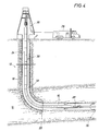
- FIGs. 1-5 sequentially illustrate the use of a remotely-engaged electrical connector with a well logging tool.
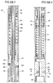
- Figs. 6A-6C illustrate the construction of the down hole half portion of the connector (the DWCH) of Fig. 1.
- Fig. 6D is a cross-sectional view taken along line 6D-6D in Fig. 6B.
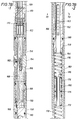
- Figs. 7A-7C illustrate the construction of the cable half portion of the connector (the PWCH) of Fig. 1.
- Fig. 7D is a cross-sectional view taken along line 7D-7D in Fig. 7B.
- Fig. 8 shows an alternative arrangement of the upper end of the PWCH.
- Fig. 9 illustrates a function of the swab cup in a pipe.
- Fig. 9A shows a swab cup arranged at the lower end of a tool.
- Fig. 10 is an enlarged, exploded view of the swab cup and related components.
- Fig. 11 is an enlarged view of the female connector assembly of Fig. 7B.
- Fig. 12 is an exploded perspective view of a sub-assembly of the female connector assembly of Fig. 11.
- Fig. 13 is an enlarged view of area 13 in Fig. 11.
- Fig. 14 is an enlarged view of the multi-pin connector of Fig. 7B.
- Fig. 15 is an end view of the connector, as viewed from direction 15 in Fig. 14.
- the downhole connection system is suitable for use with wireline logging tools 10 in either an open hole well or a cased well 12, and is especially useful in situations in which the well is deviated and/or the zone to be logged (e.g., zone 14) is at significant depth.
- well 12 has a horizontal section 16 to be logged in zone 14, and is cased with a casing 18 that extends from the well surface down to a casing shoe 20.
- logging tools 10 are equipped with a dowh hole wet-connector head (DWCH) 22 that connects between an upper end of the logging tools and drill pipe 24.
- DWCH 22 provides a male part of a downhole electrical connection for electrical communication between logging tools 10 and a mobile logging unit 26.
- logging tools 10 and DWCH 22 are lowered into well 12 on connected lengths of standard drill pipe 24 until tools 10 reach the upper end of the section of well to be logged (e.g., the top of zone 14).
- Drill pipe 24 is lowered by standard techniques and, as the drill pipe is not open for fluid inflow from the well, at regular intervals (e.g., every 2000 to 3000 feet) the drill pipe is filled with drilling fluid (i.e., mud).
- a pump-down wet-connector head (PWCH) 28 is lowered into the inner bore of the drill pipe on an electrical cable 30 that is reeled from logging unit 26.
- PWCH 28 has a female connector part to mate with the male connector part of the DWCH.
- a cable side-entry sub (CSES) 32 pre-threaded with cable 30 to provide a side exit of the cable from the made-up drill pipe, is attached to the upper end of drill pipe 24 and a mud cap 34 (e.g., of a rig top drive or Kelly mud circulation system) is attached above CSES 32 for pumping mud down the drill pipe bore.
- CSES cable side-entry sub
- Standard mud pumping equipment (not shown) is used for this purpose.
- a specially constructed swab cup on the PWCH helps to develop a pressure force on PWCH 28, due to the flow of mud down the drill pipe, to push the PWCH down the well and to latch it onto DWCH 22 to form an electrical connection.
- a special valve (explained below) in DWCH 22 allows the mud flow to circulate from the drill pipe to the well bore.
- PWCH 28 is pumped down drill pipe 24 until it latches with DWCH 22 to form an electrical connection between logging tools 10 and logging unit 26. At this point, the mud flow can be stopped and mud cap 34 removed from the top of the drill pipe. Logging tools 10 can be powered up to check system function or to perform a preliminary log as the logging tools are lowered to the bottom of the well.
- logging tools 10, DWCH 22 and PWCH 28 are lowered or pushed down to the bottom of the well by standard drill pipe methods, adding additional sections of drill pipe 24 as required.
- CSES 32 remains attached to the drill pipe, providing a side exit for cable 30.
- cable 30 lies on the outside of drill pipe 24, avoiding the need to pre-string cable 30 through any sections of drill pipe other than CSES 32.
- the lowering process is coordinated between the logging unit operator and the drill pipe operator to lower the drill pipe and the cable simultaneously.
- the sensor fingers or pad devices 36 of the logging tool are deployed, and the logging tools are pulled back up the well to the top of zone 14 as the sensor readings are recorded in well logging unit 26.
- the raising of the logging tool is coordinated between the logging unit operator and the drill pipe operator such that the cable and the drill pipe are raised simultaneously.
- DWCH 22 has two major subassemblies, the downhole wet-connector compensation cartridge (DWCC) 38 and the downhole wet-connector latch assembly (DWCL) 40.
- DWCC 38 connects to the logging tools 10 (see Fig. 1).
- the DWCL 40 is the upper end of DWCH 22, and has an outer housing 42 which connects, at its lower end, to DWCC 38 at a threaded joint 44 (Fig. 6B).
- Attached to the inside surface of DWCL housing 42 with sealed, threaded fasteners 46 is a latch assembly which has three cantilevered latch fingers 48 extending radially inwardly and toward the DWCC for securing PWCH 28.
- Two axially separated centralizers 50 are also secured about the inside of DWCL housing 42 for guiding the lower end of the PWCH to mate with the male connector assembly 52 of the DWCC.
- the DWCC 38 contains the electrical and hydraulic components of the DWCH. It has an outer housing 54 attached via a threaded joint 55 to a lower bulkhead assembly 56 havi-ng internal threads 57 at its lower end for releasably attaching the DWCH to logging tools. At the upper end of housing 54 is a threaded joint 58 joining housing 54 to a coupling 60. Split threaded sleeves 62 at joints 44, 55 and 58 enable the DWCH housing components 54, 60, 42 and 56 to be coupled without rotating either end of the DWCH. Bulkhead assembly 56 contains a sealed bulkhead electrical connector 64 for electrically connecting the DWCH to the logging tools.
- DWCC 38 One function of DWCC 38 is to provide exposed electrical contacts (in the form of male connector assembly 52) that are electrically coupled to the logging tools through bulkhead connector 64. This electrical coupling is provided through a multi-wire cable 66 that extends upward through a sealed wire chamber 68 to the individual contacts 102 of connector assembly 52. Cable 66 extends upward through an oil tube 71 through the center of the DWCH. Chamber 68 is sealed by individual o-ring contact seals 70 of connector assembly 52, o-ring seals 72 on oil tube 71, o-ring seals 74 and 76 on piston 77, and o-rings 78 on bulkhead assembly 56, and is filled with an electrically insulating fluid, such as silicone oil. The pressure in chamber 68 is maintained at approximately the pressure inside the drill pipe 24 (Fig. 1) near the top of DWCH 22 by the pressure compensation system described more fully below.
- a mud piston assembly 80 (Fig. 6B), consisting of a piston 82, a piston collar 84, a piston stop 86, seals 88 and sliding friction reducers 90, is biased in an upward direction against piston stop nut 92 by a mud piston spring 94.
- piston 82 With the mud piston assembly in the position shown, with stop 86 against nut 92, piston 82 effectively blocks fluid from moving between the well annulus 96 (the area between the drill pipe and the well bore; see Fig. 1) and the inside of the drill pipe (i.e., interior area 98) through three side ports 100 spaced about the diameter of the DWCH.
- mud piston assembly 80 In operation, mud piston assembly 80 remains in this port-blocking position until there is sufficient pressure in interior area 98 in excess of the pressure in well annulus 96 (acting against the upper end of piston 82) to overcome the biasing preload force of spring 94 and move the mud piston assembly downward, compressing spring 94 and exposing ports 100. Once exposed, ports 100 allows normal forward circulation of mud down the drill pipe and out through ports 100 into the well. Once mud pumping pressure is stopped, mud piston spring 94 forces mud piston assembly 80 back up to its port-blocking position. By blocking ports 100 in the DWCL housing 42 in the absence of mud pumping pressure in the drill pipe, mud piston assembly 80 effectively prevents undesirable inflow from the well into the drill pipe.
- Male connector assembly 52 is made up of a series of nine contact rings 102, each sealed by two o-ring seals 70 and separated by insulators 104.
- the interior of this assembly of contact rings and insulators is at the pressure of chamber 68, while the exterior of this assembly is exposed to drill pipe pressure (i.e., the pressure of interior area 98).
- drill pipe pressure i.e., the pressure of interior area 98.
- the pressure difference across the connector assembly i.e., the difference between the pressure in chamber 68 and the pressure in area 98
- Too great of a pressure difference can cause seals 70 to fail or, in extreme cases, for the connector assembly to collapse.
- the pressure compensation system maintains the pressure differential across the male connector assembly within a reasonable level, and biases the pressure difference such that the pressure in chamber 68 is slightly greater (up to 50 to 100 psi greater) than the pressure in area 98.
- This "over-compensation" of the pressure in chamber 68 causes any tendency toward leakage to result in non-conductive silicone oil from chamber 68 seeping out into area 98, rather than conductive drilling muds flowing into chamber 68.
- An annulus 106 about oil tube 71, formed in part between oil tube 71 and amud shaft 108 concentrically surrounding oil tube 71, conveys drilling mud pressure from area 98, through holes 110, to act against the upper side of piston 77. The mud pressure is transferred through piston 77, sealed by o-ring seals 74 and 76, into oil chamber 68.
- oil chamber 68 is filled with an electrically insulative fluid, such as silicone oil, through a one-way oil fill check valve 112 (Fig. 6D), such as a Lee brand check valve CKFA1876015A.
- a vacuum is first applied to the chamber through a bleed port 114. With the vacuum applied, oil is back filled into chamber 68 through bleed port 114. This is repeated a few times until the chamber has been completely filled.
- Mud chamber fill ports 120 in coupling 60 allow mud annulus 106 and the internal volume above piston 77 to be pre-filled with a recommended lubricating fluid, such as motor oil, prior to field use.
- the lubricating fluid typically remains in the DWCH (specifically in annulus 106 and the volume above piston 77) during use in the well and is not readily displaced by the drilling mud, thereby simplifying tool maintenance.
- a friction-reducing material such as LUBRIPLATETM, is recommended for all sliding contact surfaces.
- PWCH 28 contains a female connector assembly 140 for mating with the male connector assembly 52 of DWCH 22 down hole.
- a shuttle 142 of an electrically insulating material is biased to the lower end of the PWCH.
- a quad-ring seal 144 seals against the outer diameter of shuttle 142 to keep well fluids out of the PWCH until the shuttle is displaced by the male connector assembly of the DWCH.
- a tapered bottom nose 146 helps to align the PWCH for docking with the PWCH.
- the lower end of the PWCH When pushed into the DWCH by sufficient inertial or mud pressure loads, the lower end of the PWCH extends through latch fingers 48 of the DWCH (Fig. 6A) until the latch fingers snap behind a frangible latch ring 148 on the PWCH. Once latch ring 148 is engaged by the latch fingers of the DWCH, it resists disengagement of the DWCH and PWCH, e.g., due to drill pipe movement, vibration or u-tubing.
- Latch ring 148 is selectable from an assortment of rings of different maximum shear load resistances (e.g., 1600 to 4000 pounds, depending on anticipated field conditions) such that the PWCH may be released from the DWCH after data collection by pulling upward on the deployment cable until latch ring 148 shears and releases the PWCH.
- maximum shear load resistances e.g. 1600 to 4000 pounds, depending on anticipated field conditions
- the PWCH has an outer housing 150 and a rope socket housing weldment 152 connected by a coupling 154 and appropriate split threaded rings 156.
- outer housing 150 Within outer housing 150 is a wire mandrel sub-assembly with an upper mandrel 158 and a lower mandrel 160.
- Slots 162 in the upper wire mandrel and holes 163 (Fig. 7D) through the outer housing form an open flow path from the interior of the drill pipe to a mud chamber 164 within the wire mandrel sub-assembly.
- the signal wires 165 from the female connector assembly 140 are routed between the outer housing 150 and the wire mandrel along axial grooves in the outer surface of lower mandrel 160, through holes 166 in upper mandrel 158, through wire cavity 168, and individually connected to lower pins of connector assembly 170.
- the PWCH has a pressure compensation system for equalizing the pressure across shuttle 142 while keeping the electrical components surrounded by electrically insulative fluid, such as silicone oil, until the shuttle is displaced.
- An oil chamber 172 is defined within lower mandrel 160 and separated from mud chamber 164 by a compensation piston 174 with an o-ring seal 175. Piston 174 is free to move within lower mandrel 160, such that the pressure in the mud and oil chambers is substantially equal.
- Upper and lower springs 176 and 178 are disposed within mud and oil chambers 164 and 172, respectively, and bias shuttle 142 downward.
- Oil chamber 172 is in fluid communication with wire cavity 168 and the via the wire routing grooves in lower mandrel 160 and wire holes 166 in upper mandrel 158, sealed against drill pipe pressure by seals 180 about the upper mandrel. Therefore, with the shuttle positioned as shown, drill pipe fluid acts against the upper end of compensating piston 174, which transfers pressure to oil chamber 172 and the upper end of shuttle 174, balancing the fluid pressure forces on the shuttle.
- a pressure relief valve 186 in the compensating piston allows the oil chamber to be pressurized at assembly up to 100 psi over the pressure in mud chamber 164 (i.e., atmospheric pressure during assembly) .
- Connector assembly 170 has nine electrically isolated pins, each with a corresponding insulated pigtail wire 188 for electrical connection to individual wires of cable 30.
- a connector retainer 189 is threaded to the exposed end of coupling 154 to hold the connector in place. The specific construction of connector assembly 170 is discussed in more detail below.
- rope socket housing 152 is first threaded over the end of the cable, along with split cable seal 190, seal nut 192, and upper and lower swab cup mandrels 194 and 196, respectively.
- a standard, self-tightening rope socket cable retainer 197 is placed about the cable end for securing the cable end to the rope socket housing against an internal shoulder 198.
- the wires of the cable are connected to pigtail wires 188 from the connector assembly, rope socket housing 152 is attached to coupling 154 with a threaded split ring 156, and the rope socket housing is pumped full of electrically insulative grease, such as silicone grease, through grease holes 200.
- Swab cup 202 is installed between upper and lower swab cup mandrels 194 and 196 to restrict flow through the drill pipe around the PWCH and develop a pressure force for moving the PWCH along the drill pipe and latching the PWCH to the DWCH down hole.
- Upper swab cup mandrel 194 is threaded onto rope socket housing 152 to hold swab cup 202 in place, and seal nut 192 is tightened.
- an alternate arrangement for the upper end of the PWCH has two swab cups 202a and 202b, separated by a distance L, for further restricting flow around the PWCH.
- This arrangement is useful when light, low-viscosity muds are to be used for pumping, for instance.
- a rope socket housing extension 204 appropriately connects the mandrels of the two swab cups. More than two swab cups may also be used.
- swab cup 202 creates a flow restriction and a corresponding pressure drop at point A. Because the upstream pressure (e.g., the pressure at point B) is greater than the downstream pressure (e.g., the pressure at point C), a net force is developed on the swab cup to push the swab cup and its attached tool downstream. As shown in Fig. 9A, a swab cup (e.g., swab cup 202c) may alternatively be positioned near the bottom of a tool 206 to pull the tool down a pipe or well.
- a swab cup e.g., swab cup 202c
- This arrangement may be particularly useful, for example, for centering the tool to protect extended features near its downstream end or with large pipe/tool diameter ratios or small tool length/diameter ratios.
- the desired radial gap ⁇ r between the outer surface of the swab cup and the inner surface of the pipe is a function of several factors, including fluid viscosity. We have found that a radial gap of about 0.05 inch per side (i.e., a diametrical gap of 0.10 inch) works with most common well-drilling muds.
- swab cup 202 is injection molded of a resilient material such as VITON or other fluorocarbon elastomer, and has a slit 210 down one side to facilitate installation and removal without detaching the cable from the tool.
- Tapered sections 214 and 216 of the swab cup fit into corresponding bores in the upper and lower swab cup mandrels 194 and 196, respectively, and have outer surfaces that taper at about 7 degrees with respect to the longitudinal axis of the swab cup. The length of the tapered sections helps to retain the swab cup within the bores of the housing.
- swab cup extends through holes 218 in the swab cup, between the upper and lower swab cup mandrels, to retain the swab cup during use.
- Circular trim guides 219 are molded into a surface of the swab cup to aid cutting of the cup to different outer diameters to fit various pipe sizes.
- Other resilient materials can also be used for the swab cup, although ideally the swab cup material should be able to withstand the severe abrasion that can occur along the pipe walls and the great range of chemicals that can be encountered in wells.
- Non-resilient materials that are also useful are soft metals, such as brass or aluminum, or hard plastics, such as polytetrafluoroethylene (TEFLONTM) or acetal homopolymer resin (DELRINTM).
- TEFLONTM polytetrafluoroethylene
- DELRINTM acetal homopolymer resin
- Non-resilient swab cups can be formed in two overlapping pieces for installation over a pre-assembled tool.
- female connector assembly 140 of the PWCH has a series of female contacts 220 disposed about a common axis 222.
- the contacts have a linear spacing, d, that corresponds to the spacing of the male contacts of the male connector assembly of the DWCH (Fig. 6A), and a wiper seal 224.
- Contacts 220 and wiper seals 224 are each held within a corresponding insulator 226.
- the stack of contacts, wiper seals and insulators in contained within an outer sleeve 228 between an end retainer 230 and an upper mandrel 232.
- each contact 220 is machined from a single piece of electrically conductive material, such as beryllium copper, and has a sleeve portion 234 with eight (preferably six or more) extending fingers 236.
- Contact 220 is preferably gold-plated.
- Fingers 236 are each shaped to bow radially inward, in other words to have, from sleeve portion 234 to a distal end 237, a first portion 238 that extends radially inward and a second portion 240 that extends radially outward, forming a radially innermost portion 242 with a contact length d c of about 0.150 inch.
- the inner diameter d 1 of contact 220 is slightly smaller than the outer diameter of male electrical contacts 102 of the DWCH (Fig. 6A), such that fingers 236 are pushed outward during engagement with the male connector and provide a contact pressure between contact surfaces 242 and male contacts 102.
- the circumferential width, w, of each finger tapers to a minimum at contact surface 242.
- machining the contact such that the length d c of contact surfaces 242 is about one-fourth of the overall length d f of the fingers, and the radial thickness, t, of the fingers is about 75 percent of the radial distance, r, between the inner surface of sleeve portion 234 and contact surfaces 242, results in a contact construction that withstands repeated engagements.
- Wiper seals 224 are preferably molded from a resilient fluorocarbon elastomer, such as VITONTM.
- the inner diameter d 2 of wiper seals 224 is also slightly smaller than the outer diameter of the male contacts, such that the wiper seals tend to wipe debris from the male contact surface during engagement.
- the inner diameters d 1 and d 2 of the contacts and wiper seals are about equal.
- Wiper seals 224 are molded from an electrically insulative material to reduce the possibility of shorting between contacts in the presence of electrically conductive fluids.
- Contact 220 has a solder lug 244 machined on one side of its sleeve portion 234 for electrically connecting a wire 246. As shown in Fig. 12, as wired contact 220 is inserted into insulator 226, wire 246 is routed through a hole 248 in the insulator. Alignment pins 250 in other holes 248 in the insulator fit into external grooves 252 of wiper seal 224 to align the wiper seal to the insulator. A notch 254 on the wiper seal fits around solder lug 244.
- Insulators 226 and wiper seals 224 are formed with sufficient holes 248 and grooves 252, respectively, to route all of the wires 246 from each of contacts 220 in the female connector to the upper end of the assembly for attachment to seal assembly 170 (Fig. 7B).
- the distal ends 237 of the contact fingers lie within an axial groove 256 formed by an inner lip 258 of the insulator. Lip 258 protects the distal ends of the fingers from being caught on male connector assembly surfaces during disengagement of the PWCH from the DWCH.
- connector assembly 170 of the PWCH has a molded connector body 280 of an electrically insulative material, such as polyethylketone, polyethyletherketone or polyaryletherketone.
- Body 280 is designed to withstand a high static differential pressure of up to, for instance, 15,000 psi across an o-ring in o-ring groove 281, and has through holes 282 into which are pressed electrically conductive pins 284 attached to lead wires 286. (Lead wires 286 form pigtail wires 188 of Fig.
- Gold-plated pins 284 of 17-4 stainless steel are pressed into place until their lower flanges 288 rest against the bottoms of counterbores 290 in the connector body.
- a wire seal 292 is molded in place about the wires and the connector body after the insulation on the individual lead wires has been etched for better adhesion to the seal material. Seal 292 must also withstand the high differential pressures of up to 15,000 psi experienced by the connector assembly. We have found that some high temperature fluorocarbon elastomers, such as VITONTM and KALREZTM, work well for wire seal 292.
- individual pin insulators 296 are molded in place about each of pins 284 between their lower and upper flanges 288 and 298, respectively.
- Insulators 296 extend out through the plane of face 294 of the connector body about 0.120 inch, and are preferably molded of a high temperature fluorocarbon elastomer such as VITONTM or KALREZTM. Insulators 296 guard against arcing that may occur along face 294 of the connector body if, for instance, moist air or liquid water infiltrates wire cavity 168 of the PWCH (Fig. 7B). Besides guarding against undesired electrical arcing, insulators 296 also help to seal out moisture from the connection between pins 284 and lead wires 286 inside the connector body during storage and transportation.
- connector body 280 has an outer diameter d b of about 0.95 inches in order to fit within the small tool inner diameters (of down to 1.0 inch, for example) typical of down hole instrumentation.
- the assembled connector has a circular array of nine pins 284, each with corresponding insulators 296 and lead wires 286.
Abstract
Description
Claims (10)
- A female electrical connector adapted to be lowered down a well on an electrical cable for remote connection to a downhole male connector for electrical communication between the male connector and the surface of the well through the cable, said female electrical connector comprising:a housing with an attachment for securing the female electrical connector to the cable, the housing defining an inner bore with an open end for receiving the male connector;a female electrical contact within the housing, the female electrical contact being in electrical communication with the cable and comprising:a circumferential ring defining a central axis; and,a cantilever finger extending generally axially from the ring, the finger having a first portion extending generally radially inward from the ring, and a second portion extending generally radially outward from the first portion to an axially-directed, distal end, the first and second portions defining therebetween a radially innermost contact surface; and,an insulator disposed between the housing and the female electrical contact in a manner to resist electrical conduction between the female electrical contact and the housing, the insulator comprising:an outer shell disposed between the circumferential ring of the female electrical contact and the inner bore of the housing; and,an inner lip axially overlapping the distal end of the cantilever finger of the female electrical contact, the inner lip disposed radially inward of the distal end of the cantilever finger in a manner to shield the finger end against engagement with the male connector moving within the female connector.
- The female connector of claim 1 further comprising a wiper seal disposed within the housing between the open end of the housing and the female electrical contact, and arranged to engage an exposed surface of the male connector as the male connector enters the female connector, in a manner to wipe debris from the exposed surface.
- The female connector of claim 2 wherein the inner diameter of the wiper seal is about equal to the inner diameter of the female electrical contact, as defined by the radially innermost contact surface of the female electrical contact.
- The female connector of claim 1 wherein the female electrical contact further comprises a solder lug in electrical communication with and extending radially outward from the circumferential ring.
- The female connector of claim 4 wherein the insulator defines an axial wire hole extending therethrough for routing the cable to the solder lug.
- The female connector of claim 1 wherein the female electrical contact comprises at least six said cantilever fingers arranged about said circumferential ring.
- The female connector of claim 1 for use with a cable having multiple conductors, the connector comprising a series of said female electrical contacts concentrically arranged along a common axis, each of the female electrical contacts in electrical contact with a corresponding conductor of the cable, disposed within one of said insulators within the housing, and electrically insulated from the other female electrical contacts and conductors.
- The female connector of claim 7 further comprising wiper seals disposed within the housing and arranged between the female electrical contacts to engage an exposed surface of the male connector as the male connector enters the female connector, in a manner to wipe debris from the exposed surface.
- The female connector of claim 8 wherein the inner diameters of the wiper seals are about equal to the inner diameters of the female electrical contacts, as defined by the radially innermost contact surfaces of the female electrical contacts.
- The female connector of claim 1 in which the female electrical contact is formed by the process of machining the contact, in its finished form, from a unitary piece of material.
Applications Claiming Priority (4)
| Application Number | Priority Date | Filing Date | Title |
|---|---|---|---|
| US3811097P | 1997-02-19 | 1997-02-19 | |
| US38110P | 1997-02-19 | ||
| US869447 | 1997-06-05 | ||
| US08/869,447 US5967816A (en) | 1997-02-19 | 1997-06-05 | Female wet connector |
Publications (3)
| Publication Number | Publication Date |
|---|---|
| EP0860907A2 true EP0860907A2 (en) | 1998-08-26 |
| EP0860907A3 EP0860907A3 (en) | 1999-09-15 |
| EP0860907B1 EP0860907B1 (en) | 2008-03-26 |
Family
ID=26714873
Family Applications (1)
| Application Number | Title | Priority Date | Filing Date |
|---|---|---|---|
| EP98400320A Expired - Lifetime EP0860907B1 (en) | 1997-02-19 | 1998-02-11 | Female wet connector |
Country Status (11)
| Country | Link |
|---|---|
| US (1) | US5967816A (en) |
| EP (1) | EP0860907B1 (en) |
| CN (1) | CN1105404C (en) |
| AU (1) | AU743885B2 (en) |
| CA (2) | CA2229004C (en) |
| CO (1) | CO4771132A1 (en) |
| DE (1) | DE69839288T2 (en) |
| DK (1) | DK0860907T3 (en) |
| EG (1) | EG21513A (en) |
| ID (2) | ID19897A (en) |
| NO (1) | NO319684B1 (en) |
Cited By (7)
| Publication number | Priority date | Publication date | Assignee | Title |
|---|---|---|---|---|
| WO1999013535A1 (en) * | 1997-09-10 | 1999-03-18 | Radi Medical Systems Ab | Female connector with wiper device |
| WO2001033032A1 (en) * | 1999-11-05 | 2001-05-10 | Baker Hughes Incorporated | Disconnectable and reconnectable wet connector |
| GB2364451A (en) * | 2000-07-05 | 2002-01-23 | Tronic Ltd | Underwater or severe environment annular connector allowing connection in any rotational orientation |
| US6776636B1 (en) | 1999-11-05 | 2004-08-17 | Baker Hughes Incorporated | PBR with TEC bypass and wet disconnect/connect feature |
| WO2008051788A1 (en) * | 2006-10-20 | 2008-05-02 | Baker Hughes Incorporated | Downhole wet connect using piezoelectric contacts |
| WO2009065574A2 (en) * | 2007-11-23 | 2009-05-28 | Services Petroliers Schlumberger | Deployment of a wireline tool |
| EP3670831A1 (en) * | 2018-12-21 | 2020-06-24 | Sandvik Mining and Construction Oy | Rock drilling machine, rock drilling rig and measuring method |
Families Citing this family (51)
| Publication number | Priority date | Publication date | Assignee | Title |
|---|---|---|---|---|
| TW391555U (en) * | 1998-07-09 | 2000-05-21 | Delta Electronics Inc | Tube structure for winding wire |
| US6429784B1 (en) * | 1999-02-19 | 2002-08-06 | Dresser Industries, Inc. | Casing mounted sensors, actuators and generators |
| US6398583B1 (en) * | 1999-06-14 | 2002-06-04 | James N. Zehren | Apparatus and method for installing a downhole electrical unit and providing electrical connection thereto |
| US6510899B1 (en) | 2001-02-21 | 2003-01-28 | Schlumberger Technology Corporation | Time-delayed connector latch |
| DE50102005D1 (en) * | 2001-11-28 | 2004-05-19 | Festo Ag & Co | Connection piece, fluid line and fluid technology device |
| US6758272B2 (en) | 2002-01-29 | 2004-07-06 | Schlumberger Technology Corporation | Apparatus and method for obtaining proper space-out in a well |
| US7074064B2 (en) | 2003-07-22 | 2006-07-11 | Pathfinder Energy Services, Inc. | Electrical connector useful in wet environments |
| US8789772B2 (en) | 2004-08-20 | 2014-07-29 | Sdg, Llc | Virtual electrode mineral particle disintegrator |
| US20060037516A1 (en) | 2004-08-20 | 2006-02-23 | Tetra Corporation | High permittivity fluid |
| US9190190B1 (en) | 2004-08-20 | 2015-11-17 | Sdg, Llc | Method of providing a high permittivity fluid |
| US7052297B2 (en) * | 2004-08-25 | 2006-05-30 | Wireline Technologies, Inc. | Rotary connector having removable and replaceable contacts |
| US7543659B2 (en) * | 2005-06-15 | 2009-06-09 | Schlumberger Technology Corporation | Modular connector and method |
| US7913774B2 (en) | 2005-06-15 | 2011-03-29 | Schlumberger Technology Corporation | Modular connector and method |
| US7712524B2 (en) * | 2006-03-30 | 2010-05-11 | Schlumberger Technology Corporation | Measuring a characteristic of a well proximate a region to be gravel packed |
| US8056619B2 (en) | 2006-03-30 | 2011-11-15 | Schlumberger Technology Corporation | Aligning inductive couplers in a well |
| US7793718B2 (en) | 2006-03-30 | 2010-09-14 | Schlumberger Technology Corporation | Communicating electrical energy with an electrical device in a well |
| US7735555B2 (en) * | 2006-03-30 | 2010-06-15 | Schlumberger Technology Corporation | Completion system having a sand control assembly, an inductive coupler, and a sensor proximate to the sand control assembly |
| US10060195B2 (en) | 2006-06-29 | 2018-08-28 | Sdg Llc | Repetitive pulsed electric discharge apparatuses and methods of use |
| US7520768B2 (en) * | 2007-03-15 | 2009-04-21 | Schlumberger Technology Corporation | Connector assembly for use with an electrical submersible component in a deepwater environment |
| US7516783B2 (en) * | 2007-06-20 | 2009-04-14 | Petroquip Energy Services, Llp | Double pin connector and hydraulic connect with seal assembly |
| US7373970B1 (en) * | 2007-06-20 | 2008-05-20 | Petroquip Energy Services, Llp | Pin connector with seal assembly |
| US7645153B1 (en) * | 2008-06-20 | 2010-01-12 | Delphi Technologies, Inc. | Connector retainer |
| US8711655B2 (en) * | 2009-03-17 | 2014-04-29 | Schlumberger Technology Corporation | Single well reservoir characterization apparatus and methods |
| GB0906899D0 (en) * | 2009-04-22 | 2009-06-03 | Artificial Lift Co Ltd | Electrical wet connect |
| US8839850B2 (en) * | 2009-10-07 | 2014-09-23 | Schlumberger Technology Corporation | Active integrated completion installation system and method |
| US20110192596A1 (en) * | 2010-02-07 | 2011-08-11 | Schlumberger Technology Corporation | Through tubing intelligent completion system and method with connection |
| EP2395618A1 (en) * | 2010-06-08 | 2011-12-14 | Vetco Gray Controls Limited | Installing a cable in an underwater well installation |
| AU2012204152B2 (en) * | 2011-01-07 | 2017-05-04 | Sdg Llc | Apparatus and method for supplying electrical power to an electrocrushing drill |
| DE102011078284A1 (en) * | 2011-06-29 | 2013-01-03 | Tyco Electronics Amp Gmbh | Connectors, in particular electrical connectors |
| US9249559B2 (en) | 2011-10-04 | 2016-02-02 | Schlumberger Technology Corporation | Providing equipment in lateral branches of a well |
| US9644476B2 (en) | 2012-01-23 | 2017-05-09 | Schlumberger Technology Corporation | Structures having cavities containing coupler portions |
| CN103227380B (en) * | 2012-01-25 | 2017-04-05 | 英洛瓦(天津)物探装备有限责任公司 | For the seal feature that adapter is used |
| US9175560B2 (en) | 2012-01-26 | 2015-11-03 | Schlumberger Technology Corporation | Providing coupler portions along a structure |
| US9938823B2 (en) | 2012-02-15 | 2018-04-10 | Schlumberger Technology Corporation | Communicating power and data to a component in a well |
| US10036234B2 (en) | 2012-06-08 | 2018-07-31 | Schlumberger Technology Corporation | Lateral wellbore completion apparatus and method |
| US10407995B2 (en) | 2012-07-05 | 2019-09-10 | Sdg Llc | Repetitive pulsed electric discharge drills including downhole formation evaluation |
| US9052043B2 (en) | 2012-11-28 | 2015-06-09 | Baker Hughes Incorporated | Wired pipe coupler connector |
| US8986028B2 (en) * | 2012-11-28 | 2015-03-24 | Baker Hughes Incorporated | Wired pipe coupler connector |
| CA2962002C (en) | 2013-09-23 | 2021-11-09 | Sdg Llc | Method and apparatus for isolating and switching lower-voltage pulses from high voltage pulses in electrocrushing and electrohydraulic drills |
| US9270051B1 (en) * | 2014-09-04 | 2016-02-23 | Ametek Scp, Inc. | Wet mate connector |
| RU2572496C1 (en) * | 2014-09-30 | 2016-01-10 | Шлюмберже Технолоджи Б.В. | Logging system for use in well under submersible electric-centrifugal pump |
| WO2016187420A1 (en) | 2015-05-21 | 2016-11-24 | Thru Tubing Solutions, Inc. | Advancement of a tubular string into a wellbore |
| US9768546B2 (en) | 2015-06-11 | 2017-09-19 | Baker Hughes Incorporated | Wired pipe coupler connector |
| CA2946682C (en) * | 2015-10-27 | 2022-04-05 | Extensive Energy Technologies Partnership | Latching rotary connector system |
| CN106654758B (en) * | 2016-11-28 | 2019-02-15 | 中国石油天然气集团公司 | Automatically cleaning cable connector |
| US10443325B2 (en) * | 2017-09-01 | 2019-10-15 | Schlumberger Technology Corporation | Method and system for pipe conveyed logging |
| US11021926B2 (en) | 2018-07-24 | 2021-06-01 | Petrofrac Oil Tools | Apparatus, system, and method for isolating a tubing string |
| US11193347B2 (en) | 2018-11-07 | 2021-12-07 | Petroquip Energy Services, Llp | Slip insert for tool retention |
| US10844668B2 (en) | 2018-11-09 | 2020-11-24 | National Oilwell Varco, L.P. | Self-aligning wet connection capable of orienting downhole tools |
| US11180965B2 (en) | 2019-06-13 | 2021-11-23 | China Petroleum & Chemical Corporation | Autonomous through-tubular downhole shuttle |
| WO2020263272A1 (en) | 2019-06-28 | 2020-12-30 | Halliburton Energy Services, Inc. | Concentric disconnect tool with multiple electrical conductors |
Citations (3)
| Publication number | Priority date | Publication date | Assignee | Title |
|---|---|---|---|---|
| US3753206A (en) * | 1971-12-09 | 1973-08-14 | Trw Inc | Electrical connector with coaxial contacts |
| EP0289014A2 (en) * | 1987-04-30 | 1988-11-02 | Atlas Elektronik Gmbh | Water-tight plug contact connection |
| US4846269A (en) * | 1984-09-24 | 1989-07-11 | Otis Engineering Corporation | Apparatus for monitoring a parameter in a well |
Family Cites Families (3)
| Publication number | Priority date | Publication date | Assignee | Title |
|---|---|---|---|---|
| US3237149A (en) * | 1965-01-18 | 1966-02-22 | Cambridge Thermionic Corp | Electric connector |
| US5389003A (en) * | 1993-09-13 | 1995-02-14 | Scientific Drilling International | Wireline wet connection |
| US5807120A (en) * | 1996-03-06 | 1998-09-15 | Elcon Products International | Printed circuit board power distribution connector |
-
1997
- 1997-06-05 US US08/869,447 patent/US5967816A/en not_active Expired - Lifetime
-
1998
- 1998-02-05 AU AU52945/98A patent/AU743885B2/en not_active Ceased
- 1998-02-09 CA CA002229004A patent/CA2229004C/en not_active Expired - Fee Related
- 1998-02-09 CA CA002229105A patent/CA2229105C/en not_active Expired - Fee Related
- 1998-02-11 EP EP98400320A patent/EP0860907B1/en not_active Expired - Lifetime
- 1998-02-11 DK DK98400320T patent/DK0860907T3/en active
- 1998-02-11 DE DE69839288T patent/DE69839288T2/en not_active Expired - Lifetime
- 1998-02-18 ID IDP980227A patent/ID19897A/en unknown
- 1998-02-18 NO NO19980683A patent/NO319684B1/en not_active IP Right Cessation
- 1998-02-18 EG EG19898A patent/EG21513A/en active
- 1998-02-18 ID IDP980222A patent/ID19918A/en unknown
- 1998-02-19 CO CO98008928A patent/CO4771132A1/en unknown
- 1998-02-19 CN CN98104500A patent/CN1105404C/en not_active Expired - Fee Related
Patent Citations (3)
| Publication number | Priority date | Publication date | Assignee | Title |
|---|---|---|---|---|
| US3753206A (en) * | 1971-12-09 | 1973-08-14 | Trw Inc | Electrical connector with coaxial contacts |
| US4846269A (en) * | 1984-09-24 | 1989-07-11 | Otis Engineering Corporation | Apparatus for monitoring a parameter in a well |
| EP0289014A2 (en) * | 1987-04-30 | 1988-11-02 | Atlas Elektronik Gmbh | Water-tight plug contact connection |
Cited By (19)
| Publication number | Priority date | Publication date | Assignee | Title |
|---|---|---|---|---|
| WO1999013535A1 (en) * | 1997-09-10 | 1999-03-18 | Radi Medical Systems Ab | Female connector with wiper device |
| WO2001033032A1 (en) * | 1999-11-05 | 2001-05-10 | Baker Hughes Incorporated | Disconnectable and reconnectable wet connector |
| GB2360881A (en) * | 1999-11-05 | 2001-10-03 | Baker Hughes Inc | Disconnectable and reconnectable wet connector |
| GB2360881B (en) * | 1999-11-05 | 2004-03-17 | Baker Hughes Inc | A wet connect/disconnect and reconnect apparatus and method |
| US6776636B1 (en) | 1999-11-05 | 2004-08-17 | Baker Hughes Incorporated | PBR with TEC bypass and wet disconnect/connect feature |
| GB2364451A (en) * | 2000-07-05 | 2002-01-23 | Tronic Ltd | Underwater or severe environment annular connector allowing connection in any rotational orientation |
| US6561268B2 (en) | 2000-07-05 | 2003-05-13 | Tronic Limited | Connector |
| GB2364451B (en) * | 2000-07-05 | 2004-02-11 | Tronic Ltd | Well installation and electrical connector |
| WO2008051788A1 (en) * | 2006-10-20 | 2008-05-02 | Baker Hughes Incorporated | Downhole wet connect using piezoelectric contacts |
| GB2458035A (en) * | 2006-10-20 | 2009-09-09 | Baker Hughes Inc | Downhole wet connect using piezoelectric contacts |
| GB2458035B (en) * | 2006-10-20 | 2011-05-04 | Baker Hughes Inc | Downhole wet connect using piezoelectric contacts |
| EA016097B1 (en) * | 2006-10-20 | 2012-02-28 | Бейкер Хьюз Инкорпорейтед | Downhole wet connect using piezoelectric contacts |
| AU2007309220B2 (en) * | 2006-10-20 | 2012-08-02 | Baker Hughes Incorporated | Downhole wet connect using piezoelectric contacts |
| WO2009065574A2 (en) * | 2007-11-23 | 2009-05-28 | Services Petroliers Schlumberger | Deployment of a wireline tool |
| WO2009065574A3 (en) * | 2007-11-23 | 2009-09-11 | Services Petroliers Schlumberger | Deployment of a wireline tool |
| US8479830B2 (en) | 2007-11-23 | 2013-07-09 | Schlumberger Technology Corporation | Deployment of a wireline tool |
| EP3670831A1 (en) * | 2018-12-21 | 2020-06-24 | Sandvik Mining and Construction Oy | Rock drilling machine, rock drilling rig and measuring method |
| AU2019272027B2 (en) * | 2018-12-21 | 2020-10-08 | Sandvik Mining And Construction Oy | Rock drilling machine, rock drilling rig and measuring method |
| US11118402B2 (en) | 2018-12-21 | 2021-09-14 | Sandvik Mining And Construction Oy | Rock drilling machine, rock drilling rig and measuring method |
Also Published As
| Publication number | Publication date |
|---|---|
| DK0860907T3 (en) | 2008-07-14 |
| US5967816A (en) | 1999-10-19 |
| AU5294598A (en) | 1998-08-27 |
| NO980683D0 (en) | 1998-02-18 |
| CO4771132A1 (en) | 1999-04-30 |
| NO980683L (en) | 1998-08-20 |
| ID19897A (en) | 1998-08-20 |
| ID19918A (en) | 1998-08-20 |
| EP0860907A3 (en) | 1999-09-15 |
| CA2229004A1 (en) | 1998-08-19 |
| AU743885B2 (en) | 2002-02-07 |
| EP0860907B1 (en) | 2008-03-26 |
| DE69839288T2 (en) | 2009-04-16 |
| MX9801276A (en) | 1998-08-30 |
| CA2229105A1 (en) | 1998-08-19 |
| CN1105404C (en) | 2003-04-09 |
| NO319684B1 (en) | 2005-09-05 |
| CA2229004C (en) | 2000-08-15 |
| CN1199255A (en) | 1998-11-18 |
| EG21513A (en) | 2001-11-28 |
| DE69839288D1 (en) | 2008-05-08 |
| CA2229105C (en) | 2004-03-30 |
Similar Documents
| Publication | Publication Date | Title |
|---|---|---|
| US5967816A (en) | Female wet connector | |
| US5927402A (en) | Down hole mud circulation for wireline tools | |
| US5871052A (en) | Apparatus and method for downhole tool deployment with mud pumping techniques | |
| US6062905A (en) | Male pin connector | |
| US5389003A (en) | Wireline wet connection | |
| US7074064B2 (en) | Electrical connector useful in wet environments | |
| RU2468179C2 (en) | Erection joint for downhole tool | |
| US9028264B2 (en) | Downhole electrical wet connector | |
| EP1407111B1 (en) | Electrical conducting system | |
| US20070144746A1 (en) | System and Method for Connecting Multiple Stage Completions | |
| AU2002349873A1 (en) | Electrical conducting system | |
| MXPA98001278A (en) | System of circulation of mud to the fund of the perforac | |
| MXPA98001276A (en) | Hembra connector hum | |
| WO2015106826A1 (en) | Downhole electrical wet connector | |
| MXPA98001279A (en) | Apparatus and method of deployment of instrumen | |
| SA98180903B1 (en) | Well bore mud distribution system |
Legal Events
| Date | Code | Title | Description |
|---|---|---|---|
| PUAI | Public reference made under article 153(3) epc to a published international application that has entered the european phase |
Free format text: ORIGINAL CODE: 0009012 |
|
| AK | Designated contracting states |
Kind code of ref document: A2 Designated state(s): DE DK GB IT |
|
| AX | Request for extension of the european patent |
Free format text: AL;LT;LV;MK;RO;SI |
|
| PUAL | Search report despatched |
Free format text: ORIGINAL CODE: 0009013 |
|
| AK | Designated contracting states |
Kind code of ref document: A3 Designated state(s): AT BE CH DE DK ES FI FR GB GR IE IT LI LU MC NL PT SE |
|
| AX | Request for extension of the european patent |
Free format text: AL;LT;LV;MK;RO;SI |
|
| 17P | Request for examination filed |
Effective date: 20000223 |
|
| AKX | Designation fees paid |
Free format text: DE DK GB IT |
|
| 17Q | First examination report despatched |
Effective date: 20061013 |
|
| GRAP | Despatch of communication of intention to grant a patent |
Free format text: ORIGINAL CODE: EPIDOSNIGR1 |
|
| GRAS | Grant fee paid |
Free format text: ORIGINAL CODE: EPIDOSNIGR3 |
|
| GRAA | (expected) grant |
Free format text: ORIGINAL CODE: 0009210 |
|
| AK | Designated contracting states |
Kind code of ref document: B1 Designated state(s): DE DK GB IT |
|
| REG | Reference to a national code |
Ref country code: GB Ref legal event code: FG4D |
|
| REF | Corresponds to: |
Ref document number: 69839288 Country of ref document: DE Date of ref document: 20080508 Kind code of ref document: P |
|
| REG | Reference to a national code |
Ref country code: DK Ref legal event code: T3 |
|
| PLBE | No opposition filed within time limit |
Free format text: ORIGINAL CODE: 0009261 |
|
| STAA | Information on the status of an ep patent application or granted ep patent |
Free format text: STATUS: NO OPPOSITION FILED WITHIN TIME LIMIT |
|
| 26N | No opposition filed |
Effective date: 20081230 |
|
| PGFP | Annual fee paid to national office [announced via postgrant information from national office to epo] |
Ref country code: IT Payment date: 20140211 Year of fee payment: 17 |
|
| PGFP | Annual fee paid to national office [announced via postgrant information from national office to epo] |
Ref country code: GB Payment date: 20140206 Year of fee payment: 17 |
|
| PGFP | Annual fee paid to national office [announced via postgrant information from national office to epo] |
Ref country code: DE Payment date: 20140417 Year of fee payment: 17 |
|
| PGFP | Annual fee paid to national office [announced via postgrant information from national office to epo] |
Ref country code: DK Payment date: 20150210 Year of fee payment: 18 |
|
| REG | Reference to a national code |
Ref country code: DE Ref legal event code: R119 Ref document number: 69839288 Country of ref document: DE |
|
| GBPC | Gb: european patent ceased through non-payment of renewal fee |
Effective date: 20150211 |
|
| PG25 | Lapsed in a contracting state [announced via postgrant information from national office to epo] |
Ref country code: IT Free format text: LAPSE BECAUSE OF NON-PAYMENT OF DUE FEES Effective date: 20150211 |
|
| PG25 | Lapsed in a contracting state [announced via postgrant information from national office to epo] |
Ref country code: GB Free format text: LAPSE BECAUSE OF NON-PAYMENT OF DUE FEES Effective date: 20150211 Ref country code: DE Free format text: LAPSE BECAUSE OF NON-PAYMENT OF DUE FEES Effective date: 20150901 |
|
| REG | Reference to a national code |
Ref country code: DK Ref legal event code: EBP Effective date: 20160229 |
|
| PG25 | Lapsed in a contracting state [announced via postgrant information from national office to epo] |
Ref country code: DK Free format text: LAPSE BECAUSE OF NON-PAYMENT OF DUE FEES Effective date: 20160229 |