EP0860215A1 - Continuous metal manufacturing method and apparatus therefor - Google Patents
Continuous metal manufacturing method and apparatus therefor Download PDFInfo
- Publication number
- EP0860215A1 EP0860215A1 EP98301246A EP98301246A EP0860215A1 EP 0860215 A1 EP0860215 A1 EP 0860215A1 EP 98301246 A EP98301246 A EP 98301246A EP 98301246 A EP98301246 A EP 98301246A EP 0860215 A1 EP0860215 A1 EP 0860215A1
- Authority
- EP
- European Patent Office
- Prior art keywords
- rolling
- stage
- state
- steel
- strip
- Prior art date
- Legal status (The legal status is an assumption and is not a legal conclusion. Google has not performed a legal analysis and makes no representation as to the accuracy of the status listed.)
- Withdrawn
Links
Images


Classifications
-
- B—PERFORMING OPERATIONS; TRANSPORTING
- B21—MECHANICAL METAL-WORKING WITHOUT ESSENTIALLY REMOVING MATERIAL; PUNCHING METAL
- B21B—ROLLING OF METAL
- B21B1/00—Metal-rolling methods or mills for making semi-finished products of solid or profiled cross-section; Sequence of operations in milling trains; Layout of rolling-mill plant, e.g. grouping of stands; Succession of passes or of sectional pass alternations
- B21B1/46—Metal-rolling methods or mills for making semi-finished products of solid or profiled cross-section; Sequence of operations in milling trains; Layout of rolling-mill plant, e.g. grouping of stands; Succession of passes or of sectional pass alternations for rolling metal immediately subsequent to continuous casting
- B21B1/463—Metal-rolling methods or mills for making semi-finished products of solid or profiled cross-section; Sequence of operations in milling trains; Layout of rolling-mill plant, e.g. grouping of stands; Succession of passes or of sectional pass alternations for rolling metal immediately subsequent to continuous casting in a continuous process, i.e. the cast not being cut before rolling
-
- B—PERFORMING OPERATIONS; TRANSPORTING
- B21—MECHANICAL METAL-WORKING WITHOUT ESSENTIALLY REMOVING MATERIAL; PUNCHING METAL
- B21B—ROLLING OF METAL
- B21B1/00—Metal-rolling methods or mills for making semi-finished products of solid or profiled cross-section; Sequence of operations in milling trains; Layout of rolling-mill plant, e.g. grouping of stands; Succession of passes or of sectional pass alternations
- B21B1/22—Metal-rolling methods or mills for making semi-finished products of solid or profiled cross-section; Sequence of operations in milling trains; Layout of rolling-mill plant, e.g. grouping of stands; Succession of passes or of sectional pass alternations for rolling plates, strips, bands or sheets of indefinite length
- B21B1/24—Metal-rolling methods or mills for making semi-finished products of solid or profiled cross-section; Sequence of operations in milling trains; Layout of rolling-mill plant, e.g. grouping of stands; Succession of passes or of sectional pass alternations for rolling plates, strips, bands or sheets of indefinite length in a continuous or semi-continuous process
- B21B1/26—Metal-rolling methods or mills for making semi-finished products of solid or profiled cross-section; Sequence of operations in milling trains; Layout of rolling-mill plant, e.g. grouping of stands; Succession of passes or of sectional pass alternations for rolling plates, strips, bands or sheets of indefinite length in a continuous or semi-continuous process by hot-rolling, e.g. Steckel hot mill
-
- C—CHEMISTRY; METALLURGY
- C21—METALLURGY OF IRON
- C21D—MODIFYING THE PHYSICAL STRUCTURE OF FERROUS METALS; GENERAL DEVICES FOR HEAT TREATMENT OF FERROUS OR NON-FERROUS METALS OR ALLOYS; MAKING METAL MALLEABLE, e.g. BY DECARBURISATION OR TEMPERING
- C21D8/00—Modifying the physical properties by deformation combined with, or followed by, heat treatment
- C21D8/12—Modifying the physical properties by deformation combined with, or followed by, heat treatment during manufacturing of articles with special electromagnetic properties
- C21D8/1216—Modifying the physical properties by deformation combined with, or followed by, heat treatment during manufacturing of articles with special electromagnetic properties the working step(s) being of interest
- C21D8/1227—Warm rolling
-
- B—PERFORMING OPERATIONS; TRANSPORTING
- B21—MECHANICAL METAL-WORKING WITHOUT ESSENTIALLY REMOVING MATERIAL; PUNCHING METAL
- B21B—ROLLING OF METAL
- B21B13/00—Metal-rolling stands, i.e. an assembly composed of a stand frame, rolls, and accessories
- B21B13/02—Metal-rolling stands, i.e. an assembly composed of a stand frame, rolls, and accessories with axes of rolls arranged horizontally
- B21B13/023—Metal-rolling stands, i.e. an assembly composed of a stand frame, rolls, and accessories with axes of rolls arranged horizontally the axis of the rolls being other than perpendicular to the direction of movement of the product, e.g. cross-rolling
-
- B—PERFORMING OPERATIONS; TRANSPORTING
- B21—MECHANICAL METAL-WORKING WITHOUT ESSENTIALLY REMOVING MATERIAL; PUNCHING METAL
- B21B—ROLLING OF METAL
- B21B2201/00—Special rolling modes
- B21B2201/02—Austenitic rolling
-
- B—PERFORMING OPERATIONS; TRANSPORTING
- B21—MECHANICAL METAL-WORKING WITHOUT ESSENTIALLY REMOVING MATERIAL; PUNCHING METAL
- B21B—ROLLING OF METAL
- B21B2201/00—Special rolling modes
- B21B2201/04—Ferritic rolling
-
- B—PERFORMING OPERATIONS; TRANSPORTING
- B21—MECHANICAL METAL-WORKING WITHOUT ESSENTIALLY REMOVING MATERIAL; PUNCHING METAL
- B21B—ROLLING OF METAL
- B21B37/00—Control devices or methods specially adapted for metal-rolling mills or the work produced thereby
- B21B37/16—Control of thickness, width, diameter or other transverse dimensions
- B21B37/24—Automatic variation of thickness according to a predetermined programme
Definitions
- the present invention relates to a continuous metal manufacturing method and apparatus therefor and in particular of steel.
- US-A-5018569 discloses a method of measuring and adjusting the roll speeds of rolls in a continuous casting line in order to monitor the onset of solidification to ensure that the point of solidification is maintained at essentially the same position. Whilst this is useful in maintaining the quality of the finished product it does not assist in control of the subsequent rolling of the cast slab.
- EP-A-0666122 discloses a method of hot rolling of discrete slabs and specifically that the stock is re-heated between the first and second rolling stages. There is a high risk of cobbling with this process. Also with this method rolling in the austenitic phase only is provided for there is no provision for rolling in the ferritic phase which has to be carried out in a separate operation.
- WO 92/00815 discloses a continuous casting and rolling process for the production of steel strip. With this process hot rolling is followed by heating then further hot rolling then cooling and finally ferritic rolling. Therefore when it is not required to roll ferritically the last stands are redundant.
- An objective of the invention is to remove the need for a buffer stock and reduce the amount of material in any particular production run.
- a consequential objective of the invention is to reduce the assets tied up in the casting and rolling processes and decrease the minimum optimum order size and to increase the flexibility of production and to reduce processing time.
- a method for the manufacture of steel, in the form of rod, bar or strip, from the molten metal to the final rolled product comprising a casting process and a rolling process, wherein the rolling process includes a first rolling stage followed by a second rolling stage, the first and second rolling stages each comprising between one and six rolling stands, wherein the casting process and the rolling process are continuous and the flow rate of the molten metal into the casting process is balanced with the flow rate of the strip throughout the rolling process, and wherein a temperature controlling stage is arranged between the first and second rolling stages, characterised in that, the temperature controlling stage comprises a first state in which it operates to prepare the steel for rolling in the subsequent second rolling stage in the austenitic phase, and an alternative second state in which the temperature controlling stage operates to prepare the steel for the subsequent rolling stage in the ferritic phase, said temperature controlling stage being selectively operable between the first state and the second state, such that the steel passes through the same subsequent second rolling stage, correspondingly in the austenitic phase or alternatively the ferr
- the temperature controlling means comprises a heat retaining means which in the first state encloses the steel to retain heat therein and is openable to form the second state in which the steel is exposed to the surrounding cooling air.
- the temperature controlling means comprises a heat providing or retaining means and a separate heat removing or cooling means.
- the heat providing or retaining means and heat removing means are arranged in parallel, and in the first state, the heat providing or retaining means is arranged in-line with first and second rolling stages and the heat removing means are arranged off-line, and in the second state the heat removing means are arranged in-line with the first and second rolling stages and the heat providing or retaining means is arranged off-line.
- the heat providing or retaining means and heat removing means are arranged in series in-line with each other, and in the first state, the heat providing or retaining means is switched to an operating state and the heat removing means is switched to an off state, and in the second state the heat removing means is switched to an on state and the heat providing or retaining means is switched to an off state.
- the temperature controlling stage preferably includes a cooling stage which is preferably provided by forced cooling, such as by water cooling.
- the temperature controlling stage preferably includes a heating stage which may be by induction heating.
- the casting speed is of the order of 6 metres/minute with a slab thickness of 70 mm and a corresponding range of final thin gauge strip from 0.75 mm to 5 mm the cast slab thickness is in the range of 55 to 85 mm and the continuous casting slab speed is in the range of 4.8 to 7.2 metres/minute.
- the steel is preferably maintained with a flow rate product of at least 0.315 metres 2 /minute.
- the gauge and shape of the strip may be changed continuously without interruption to the combined casting and rolling process, by controlling the roll gaps and the speed of the whole casting and rolling process in a synchronous way, at least one of the first and second rolling stages comprising at least one rolling stand comprising at least one dynamic shape actuated shell roll.
- an apparatus for the manufacture of steel, in the form of rod, bar or strip, from the molten metal to the final rolled product comprising a casting stage and first and second rolling stages, the first and second rolling stages each comprising between one and six rolling stands, wherein the casting stage and the rolling stages are continuous and the flow rate of the molten metal into the casting stage is balanced with the flow rate of the strip throughout the rolling stages, and wherein a temperature controlling stage is arranged between the first and second rolling stages, characterised in that, the temperature controlling stage comprises a first state in which it operates to prepare the steel for rolling in the subsequent second rolling stage in the austenitic phase, and an alternative second state in which the temperature controlling stage operates to prepare the steel for the subsequent rolling stage in the ferritic phase, said temperature controlling stage being selectively operable between the first state and the second state, such that the steel passes through the same subsequent second rolling stage, correspondingly in the austenitic phase or alternatively the ferritic phase.
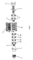
- FIG. 1 shows one embodiment of the apparatus which comprises a casting process 2 and a rolling process 3 for the production of steel strip.
- Molten steel enters the continuous casting process stage 2 where it solidifies.
- a continuous slab 5 is formed with a slab thickness starting at 90 mm and reducing to 70 mm by the stage where the casting or solidification process is complete.
- the continuous slab 5 is then guided to a descaling section 8 before going on to a first rolling stand 10a of the rolling process 4.
- the continuous slab continues through the second, third and fourth stands 10a, 10b, 10c of the rolling process 4 resulting in a reduction in the thickness of the slab to 2 mm.
- This 2 mm thickness at this stage is shown for a particular example of a required final gauge of strip.
- the thickness of the strip could be as high as 5 mm depending on the desired final gauge.
- the slab 5 we shall refer to the slab 5 as strip 6 because this is a more accurate description of the steel with now much reduced thickness dimensions.
- the velocity of the slab/strip 5/6 has correspondingly increased from 0. 1 m/s to 3.5 m/s.
- the strip 6 then enters a re-heating and homogenisation stage 11b to restore the strip to the desired temperature for the subsequent rolling operations and in particular the edges of the strip which will have cooled down much more than the centre during the first rolling stage 10.
- This restores or maintains the steel of the strip in the austenitic phase to avoid the phase change to the ferritic phase.
- This enables further rolling to take place in the austenitic phase.
- the volume changes associated with the phase change from austenitic to ferritic prevent satisfactory rolling from taking place during the phase change, and the metallurgical properties of the resulting strip would not be of the required specification.
- the heating stage includes an electrical induction heater.
- the strip 6 passes through a second descaling stage 12 before proceeding to two further rolling stands 13a, 13b and has then achieved the desired thickness of 0.75 mm.
- the velocity of the strip has correspondingly increased to 9.3 m/s.
- the final thickness again could be as high as 5 mm according to the required final product specification and the fmal velocity would be correspondingly lower.
- the strip then passes through a cooling section 14 which in this embodiment is merely an extended distance between the last rolling stage 13 and the coiling stage 15. This distance in this case is 50 metres. Again this distance may be varied according to the requirements of any particular product specification within the scope of the invention.
- the strip then meets the final coiling stage 15 where the strip is coiled into conveniently sized coils.
- This coiling station preferably includes a cutting stage as well as an automatic means of re-starting a new coil.
- the re-heating and homogenisation stage 11b is replaced with an additional cooling means 11a which actually speeds up the conversion from the austenitic. phase to the ferritic phase so that the conversion to the ferritic phase is essentially complete before the strip reaches subsequent rolling stands.
- the final rolling stages take place with the strip in the ferritic phase.
- any rolling of the strip whilst the conversion of the steel strip from the austenitic phase to the ferritic phase is taking place is avoided. It may be sufficient to just turn off the re-heater 9 to achieve the required cooling to convert the steel strip to the ferritic phase without any need for additional cooling means.
- the essence of the invention is the two stage rolling process in which the first and second rolling stages are separated to ensure that either the steel is maintained in the austenitic phase before the second stage by re-heating or that the steel is converted to the ferritic phase before the second rolling stage if necessary by forced cooling.
- the first rolling stage has four rolling stands and the second rolling stage has two rolling stands, the first rolling stage could have between two and four rolling stands and the second rolling stage could have between one and three rolling stands.
- a slab shearing device is incorporated at the exit of the caster to divide the strip in the event of certain delays or disturbances in the upstream or downstream process.
- a buffer is created which may alleviate the need to stop the caster and therefore moderating the extent of production loss due to the delay or disturbance of the rolling stage.
- the shearing means is arranged to operate intermittently only since such shearing will only be required in the event of delay or disturbances in the process.
- the shearing means is preferably a mechanical shearing device.
- the specific thickness, corresponding velocity and the length are shown for each of the stages in figure 4. All these values will vary according to the type of steel produced and in particular the desired size of the finished strip.
- the required mass flow of the cast material can be used to define the as cast slab thickness as well as the as cast slab speed.
- Figure 2 shows how this can be done.
- the mass flow curve A of the as cast slab is plotted as a product of the slab speed and the slab thickness which are the respective axes.
- the horizontal line B is a simplified representation of the upper limit of the as cast slab thickness for a given number of rolling mill passes.
- the vertical line C is a simplified representation of the upper limit for the as cast slab speed which is determined by operational criteria of the casting process.
- the desired cast speed and thickness can be chosen from the area to the right and above curve A within the limits of lines B and C. Within these limits it is desirable, when in the steady state, to maximise the throughput and therefore be as close as possible to the cross over of lines B and C.
- the flow rate will be reduced from the maximum due, for example, to changeovers in various wear components of the casting process, such as the submerged entry nozzles, and it is necessary to ensure that none of these events cause the flow rate to be reduced to such an extent that either the cast velocity or the product thickness falls below curve A on figure 2.
- Band B shows the preferred range for optimum finished quality, additionally taking into account other factors such as the optimum wear on the components in the casting process having an impact on the overall costs of the process.
- Line D shows a thickness reduction from 50 to 0.7
- line E from 60 to 0.7
- line F from 70 to 0.7
- line G from 80 to 0.7
- line H from 90 to 0.7
- line J from 100 to 0.7
- line K from 110 to 0.7
- the final desired thickness in this example is 0.7 mm.
- the optimum casting speed should be of the order of 6 metres/minute with a slab thickness of 70 mm. Satisfactory results can be achieved for a corresponding range of final thin gauge strip from 0.75 mm to 5 mm with a cast slab thickness in the range of 55 to 85 mm and a continuous casting slab speed of 4.8 to 7.2 metres/minute.
- the critical parameters may be simplified in the flow rate product which is the product of the thickness and the speed. This flow rate is itself a critical parameter and according to the invention it has been determined that this should be at least 0.315 metres 2 /minute. This linear flow rate lower limit can be applied for any width of strip.
- molten steel is formed into the final finished strip by means of the combined casting process stage 2, a first re-heating and homogenisation furnace 3, a rolling process stage 4 and a final coiling stage 5.
- the strand length then enters the re-heating and homogenisation furnace which is preferably a tunnel furnace 3.
- the purpose of the tunnel furnace is to ensure that the strand is at the required temperature across the whole profile of the strand for the subsequent rolling operation.
- the required temperature of the strand depends therefore on the further processing requirements of the final strip and thus additional heating may be required as well as maintenance of the desired temperature by means soaking requiring the addition of heat or possibly merely by heat insulation.
- a second continuous cast strand could be introduced from a separate casting unit so that the generally slower throughput of the casting unit can be balanced with the generally higher throughput of the rolling process so that the throughput capacity of the rolling process is more fully utilised.
- the second continuous cast strand can be switched into the line when the first casting line is paused.
- the next stage of the strip-making apparatus is a descaling stage 8, shown on fig. 4, 5.
- An edging stage (not shown) may optionally be provided at this stage before the rolling operation.
- the strand now enters the rolling process stage 4 which in this embodiment includes a first rolling stage 10 which in this embodiment includes four rolling stands 10 and a second rolling stage 13 which in this embodiment includes two rolling stands separated by a temperature controlling stage 11 between them.
- a further scale suppression stage or de-scaling unit 12 is also provided between them.
- the temperature controlling stage 11 comprises both a reheating/homogenisation function 11b or alternatively a cooling function 11a.
- this stage is required to be a cooling stage 11a which is required for certain types of steel strip to allow the transformation of the steel from the austenitic phase to the ferritic phase so that the transformation takes place before further rolling rather than during subsequent rolling.
- the cooling unit 11a and the re-heating /homogenisation unit 11b of the temperature controlling stage are arranged side by side so that desired unit for the function that is required for a particular subsequent rolling operation.
- the cooling unit 11a is arranged to line with the path of the strip.
- the cooling unit 11a is moved sideways out off line and the re-heating/homogenisation unit is moved sideways into line with the path of the strip.
- Rolling stage 13 is the finishing rolling stage with, in this embodiment, two rolling stands, although more stages may be required. Also the first rolling stage could have an alternative number of stands typically having from two to six stands. Preferably low inertia hydraulic loopers may be provided (not shown) and also optional scale suppression between each stand.
- the rolled strip is then fed to a run out table 14 which may also be provided with optional cooling 14a, in addition to normal air cooling.
- the coiling stage may include a first pinch roll which is provided in front of a shear which is followed by a separate optional pinch roll and then the coiling stage, all of which enable the desired final strip lengths to be cut and coiled whilst being continuously fed from the mill.
- the apparatus includes a control system with means for measuring the speed of the strip and the strands, as well as the profile, shape, thickness and width of the strip and also the lateral position of the strip.
- the control system is also linked to temperature measuring sensors in numerous places along the whole apparatus as well as tension measurement in the rolling process.
- the control system is linked to an actuating system which varies all of these parameters.
- the speed and tension of the strip is controlled by the roll speeds, and the profile, shape, gauge, width and lateral alignment is controlled by the mould, the roll gap, actuating means such as dynamic shape rolls (DRS) rolls and by guide rolls.
- the temperature is adjusted by the heating means in the tunnel furnace as well as cooling at the casting unit and/or by temperature modifications at the re-heating/homogenisation/cooling stage 11 and/or at each or some of the rolling stands.
- the gauge of the strip may be changed during the rolling process by controlling the roll gaps and the speed of the whole casting and rolling process in a synchronous way.
- each strand As each strand enters the rolling process it has to be threaded through the rolling stands and this occurs at a threading speed which is lower than the desired final rolling speed.
- This lower threading speed is equivalent to the speed as is presently used in the conventional rolling of strip from slabs or strand lengths rolled from cast slabs but at the highest possible practical speed or this conventional rolling.
- the speed is increased significantly and tension can be induced in the strip.
- the strand is very long, compared to conventional single cast slab strands, and rolling can thus take place at this higher speed in conditions which are very near steady state conditions.
- the temperature of the strip during rolling is higher than during threading or during rolling of conventional cast slab lengths. This allows thinner gauges to be produced.
- edge guidance is provided by roll tilting which is itself based on measurements of the lateral position of the strip.
- the width/thickness ratio is higher and it is more difficult to achieve good flatness quality.
- cooling unit 11a arranged in-line with the re-heating/homogenisation unit 11b.
- the cooling unit 11a is activated and the re-heat/homogenisation unit 11b is de-activated.
- the cooling unit 11a is de-activated and the re-heating/homogenisation unit 11b is activated and the austenitic rolling can then occur through the same rolling stage 13.
- cooling stage 11a is provided by allowing the strip to pass through a sufficient distance to permit cooling to take place by air circulation and radiation.
- the re-heating unit is of course de-activated but also has the tops of the unit raised to permit cooling by air circulation through the heating unit in the cooling mode. Cooling could be provided by forced air or nitrogen flow cooling in the re-heater or in the extended distance or both.
Abstract
The invention relates to a method for the manufacture of steel, in the form of
rod, bar or strip, from the molten metal to the final rolled product comprising a
casting (2) process and a rolling process coupled together with a balanced mass
flow rate, wherein the rolling process includes a first rolling stage (10A,10B,10C,10D) followed by
a second rolling stage (13), and wherein a temperature controlling stage is arranged
between the first and second rolling stages, which comprises a first state in
which it operates to prepare the steel for rolling in the austenitic phase, and an
alternative second state in which the temperature controlling stage operates to
prepare the steel for rolling in the ferritic phase, said temperature controlling
stage being selectively operable between the first state and the second state,
such that the steel passes through the same subsequent second rolling stage,
correspondingly in the austenitic phase or alternatively the ferritic phase. The
temperature controlling means may comprises a heat retaining means which, in
the first state encloses the steel to retain heat therein, and is openable to form
the second state, in which the steel is exposed to the surrounding cooling air.
Alternatively, it may comprises a heat providing or retaining means (11b) and a
separate heat removing or cooling means (11a) arranged either in parallel with the
selected temperature control means, being arranged in-line or in series, on-line.
Description
The present invention relates to a continuous metal manufacturing method and
apparatus therefor and in particular of steel.
Conventionally steel strip, rod or bar has been made by casting discrete slabs of
steel in the foundry or steel making plant and transferring the slabs to a rolling
mill where they are progressively rolled in a series of rolling mill stages or
stands. The slabs will typically be re-heated before the rolling commences.
The slab may be passed back and forth through a first rolling stand before the
required reduction in thickness is achieved before proceeding to the next rolling
stand. As the slab is progressively rolled its section is reduced and its length
increased and in the later rolling stands the slab becomes a long strip and will
enter the subsequent rolling stand before leaving the previous stage. The
speeds of these rolling stands will therefore have to be matched. A degree of
looping of the strip between the stages is conveniently permitted in order that
there is some tolerance in the matching of the speeds of the respective stages.
For strip, the final strip of the desired thickness and width is coiled at a coiling
stage and each coil will correspond to the respective slab from which it was
made.
With the recent development of continuous casting, conventionally the casting
and rolling operations have continued to be separate discontinuous processes.
This is convenient because the processing speeds for the casting and rolling
processes are different. The output of a rolling mill is typically faster than the
output of the casting process. Also down time for the rolling mill is usually
much more frequent than that for the casting process and the caster machine is
generally able to continue operating for a larger number of producing hours per
year than a rolling mill. These differences in rates are typically managed by the
holding of a small buffer stock between the caster and the mill. This buffer
stock is part of the total amount of work in progress which contributes to the
assets tied up in the process. It also adds to the total amount of material tied up
in a particular order for a particular size and type of material strip, and also
requires significant energy input to maintain the slabs at the required
temperature for rolling.
US-A-5018569 discloses a method of measuring and adjusting the roll speeds
of rolls in a continuous casting line in order to monitor the onset of
solidification to ensure that the point of solidification is maintained at
essentially the same position. Whilst this is useful in maintaining the quality of
the finished product it does not assist in control of the subsequent rolling of the
cast slab.
EP-A-0666122 discloses a method of hot rolling of discrete slabs and
specifically that the stock is re-heated between the first and second rolling
stages. There is a high risk of cobbling with this process. Also with this
method rolling in the austenitic phase only is provided for there is no provision
for rolling in the ferritic phase which has to be carried out in a separate
operation.
WO 92/00815 discloses a continuous casting and rolling process for the
production of steel strip. With this process hot rolling is followed by heating
then further hot rolling then cooling and finally ferritic rolling. Therefore when
it is not required to roll ferritically the last stands are redundant.
It is an objective of the invention to provide a method of continuously coupled
casting and rolling of steel strip enabling rolling in the austenitic phases as well
as the ferritic phase with the minimum number of rolling stands and minimum
line length.
It is an objective of the invention to provide a method of the continuous
coupled casting arid rolling of steel strip, wherein the flow of material through
the rolling mill is coupled with the flow from the casting machine so that the
combined process is continuous. An objective of the invention is to remove the
need for a buffer stock and reduce the amount of material in any particular
production run. A consequential objective of the invention is to reduce the
assets tied up in the casting and rolling processes and decrease the minimum
optimum order size and to increase the flexibility of production and to reduce
processing time.
It is also an objective of the invention to provide an apparatus and a method of
continuous coupled casting and rolling or strip, in particular of thin gauge metal
strip, which has a low energy consumption.
According to the invention there is provided a method for the manufacture of
steel, in the form of rod, bar or strip, from the molten metal to the final rolled
product comprising a casting process and a rolling process, wherein the rolling
process includes a first rolling stage followed by a second rolling stage, the first
and second rolling stages each comprising between one and six rolling stands,
wherein the casting process and the rolling process are continuous and the flow
rate of the molten metal into the casting process is balanced with the flow rate
of the strip throughout the rolling process, and wherein a temperature
controlling stage is arranged between the first and second rolling stages,
characterised in that, the temperature controlling stage comprises a first state in
which it operates to prepare the steel for rolling in the subsequent second
rolling stage in the austenitic phase, and an alternative second state in which
the temperature controlling stage operates to prepare the steel for the
subsequent rolling stage in the ferritic phase, said temperature controlling stage
being selectively operable between the first state and the second state, such that
the steel passes through the same subsequent second rolling stage,
correspondingly in the austenitic phase or alternatively the ferritic phase.
Preferably the temperature controlling means comprises a heat retaining means
which in the first state encloses the steel to retain heat therein and is openable
to form the second state in which the steel is exposed to the surrounding
cooling air.
Alternatively, the temperature controlling means comprises a heat providing or
retaining means and a separate heat removing or cooling means. Preferably the
heat providing or retaining means and heat removing means are arranged in
parallel, and in the first state, the heat providing or retaining means is arranged
in-line with first and second rolling stages and the heat removing means are
arranged off-line, and in the second state the heat removing means are arranged
in-line with the first and second rolling stages and the heat providing or
retaining means is arranged off-line. Alternatively, the heat providing or
retaining means and heat removing means are arranged in series in-line with
each other, and in the first state, the heat providing or retaining means is
switched to an operating state and the heat removing means is switched to an
off state, and in the second state the heat removing means is switched to an on
state and the heat providing or retaining means is switched to an off state.
The temperature controlling stage preferably includes a cooling stage which is
preferably provided by forced cooling, such as by water cooling.
The temperature controlling stage preferably includes a heating stage which
may be by induction heating.
Preferably the casting speed is of the order of 6 metres/minute with a slab
thickness of 70 mm and a corresponding range of final thin gauge strip from
0.75 mm to 5 mm the cast slab thickness is in the range of 55 to 85 mm and the
continuous casting slab speed is in the range of 4.8 to 7.2 metres/minute.
The steel is preferably maintained with a flow rate product of at least 0.315
metres2/minute.
The gauge and shape of the strip may be changed continuously without
interruption to the combined casting and rolling process, by controlling the roll
gaps and the speed of the whole casting and rolling process in a synchronous
way, at least one of the first and second rolling stages comprising at least one
rolling stand comprising at least one dynamic shape actuated shell roll.
According to the invention there is provided an apparatus for the manufacture
of steel, in the form of rod, bar or strip, from the molten metal to the final
rolled product comprising a casting stage and first and second rolling stages,
the first and second rolling stages each comprising between one and six rolling
stands, wherein the casting stage and the rolling stages are continuous and the
flow rate of the molten metal into the casting stage is balanced with the flow
rate of the strip throughout the rolling stages, and wherein a temperature
controlling stage is arranged between the first and second rolling stages,
characterised in that, the temperature controlling stage comprises a first state in
which it operates to prepare the steel for rolling in the subsequent second
rolling stage in the austenitic phase, and an alternative second state in which
the temperature controlling stage operates to prepare the steel for the
subsequent rolling stage in the ferritic phase, said temperature controlling stage
being selectively operable between the first state and the second state, such that
the steel passes through the same subsequent second rolling stage,
correspondingly in the austenitic phase or alternatively the ferritic phase.
There now follows a more detailed description of a specific embodiment of the
method and apparatus according to the invention with the aid of the attached
drawings in which:
Referring to the figures embodiments of the invention are shown of a method
and apparatus for the manufacture of steel strip, from the molten metal to the
final strip comprising a casting process and a rolling process. Figure 1 shows
one embodiment of the apparatus which comprises a casting process 2 and a
rolling process 3 for the production of steel strip. Molten steel enters the
continuous casting process stage 2 where it solidifies. During the solidification
in the casting process 2 a continuous slab 5 is formed with a slab thickness
starting at 90 mm and reducing to 70 mm by the stage where the casting or
solidification process is complete. The continuous slab 5 is then guided to a
descaling section 8 before going on to a first rolling stand 10a of the rolling
process 4. After the first rolling stand 10a, the continuous slab continues
through the second, third and fourth stands 10a, 10b, 10c of the rolling process
4 resulting in a reduction in the thickness of the slab to 2 mm. This 2 mm
thickness at this stage is shown for a particular example of a required final
gauge of strip. At this stage the thickness of the strip could be as high as 5 mm
depending on the desired final gauge. At this stage we shall refer to the slab 5
as strip 6 because this is a more accurate description of the steel with now
much reduced thickness dimensions. As the whole process is continuous the
velocity of the slab/strip 5/6 has correspondingly increased from 0. 1 m/s to 3.5
m/s.
In one mode of the embodiment shown after the strip exits the first rolling stage
the strip 6 then enters a re-heating and homogenisation stage 11b to restore the
strip to the desired temperature for the subsequent rolling operations and in
particular the edges of the strip which will have cooled down much more than
the centre during the first rolling stage 10. This restores or maintains the steel
of the strip in the austenitic phase to avoid the phase change to the ferritic
phase. This enables further rolling to take place in the austenitic phase. The
volume changes associated with the phase change from austenitic to ferritic
prevent satisfactory rolling from taking place during the phase change, and the
metallurgical properties of the resulting strip would not be of the required
specification. Preferably the heating stage includes an electrical induction
heater.
Following the re-heating and temperature homogenisation stage 11b, the strip 6
passes through a second descaling stage 12 before proceeding to two further
rolling stands 13a, 13b and has then achieved the desired thickness of 0.75 mm.
The velocity of the strip has correspondingly increased to 9.3 m/s. The final
thickness again could be as high as 5 mm according to the required final
product specification and the fmal velocity would be correspondingly lower.
The strip then passes through a cooling section 14 which in this embodiment is
merely an extended distance between the last rolling stage 13 and the coiling
stage 15. This distance in this case is 50 metres. Again this distance may be
varied according to the requirements of any particular product specification
within the scope of the invention. The strip then meets the final coiling stage
15 where the strip is coiled into conveniently sized coils. This coiling station
preferably includes a cutting stage as well as an automatic means of re-starting
a new coil.
In an alternative mode of the embodiment the re-heating and homogenisation
stage 11b is replaced with an additional cooling means 11a which actually
speeds up the conversion from the austenitic. phase to the ferritic phase so that
the conversion to the ferritic phase is essentially complete before the strip
reaches subsequent rolling stands. In this case the final rolling stages take
place with the strip in the ferritic phase. Importantly any rolling of the strip
whilst the conversion of the steel strip from the austenitic phase to the ferritic
phase is taking place is avoided. It may be sufficient to just turn off the re-heater
9 to achieve the required cooling to convert the steel strip to the ferritic
phase without any need for additional cooling means.
Thus it will be seen that the essence of the invention is the two stage rolling
process in which the first and second rolling stages are separated to ensure that
either the steel is maintained in the austenitic phase before the second stage by
re-heating or that the steel is converted to the ferritic phase before the second
rolling stage if necessary by forced cooling. Thus although in the embodiment
shown the first rolling stage has four rolling stands and the second rolling stage
has two rolling stands, the first rolling stage could have between two and four
rolling stands and the second rolling stage could have between one and three
rolling stands.
In an alternative embodiment a slab shearing device is incorporated at the exit
of the caster to divide the strip in the event of certain delays or disturbances in
the upstream or downstream process. By this means and due to the relatively
slow speed of the slab at the caster exit, a buffer is created which may alleviate
the need to stop the caster and therefore moderating the extent of production
loss due to the delay or disturbance of the rolling stage. The shearing means is
arranged to operate intermittently only since such shearing will only be
required in the event of delay or disturbances in the process. The shearing
means is preferably a mechanical shearing device.
The specific thickness, corresponding velocity and the length are shown for
each of the stages in figure 4. All these values will vary according to the type
of steel produced and in particular the desired size of the finished strip. In
order to produce the final desired strip from this continuous casting and rolling
process of the invention it is necessary to balance the casting mass flow with
the mass flow of the strip. Thus the required mass flow of the cast material can
be used to define the as cast slab thickness as well as the as cast slab speed.
Figure 2 shows how this can be done. The mass flow curve A of the as cast
slab is plotted as a product of the slab speed and the slab thickness which are
the respective axes. The horizontal line B is a simplified representation of the
upper limit of the as cast slab thickness for a given number of rolling mill
passes. The vertical line C is a simplified representation of the upper limit for
the as cast slab speed which is determined by operational criteria of the casting
process. Thus the desired cast speed and thickness can be chosen from the area
to the right and above curve A within the limits of lines B and C. Within these
limits it is desirable, when in the steady state, to maximise the throughput and
therefore be as close as possible to the cross over of lines B and C. During
production there will be a number of times when the flow rate will be reduced
from the maximum due, for example, to changeovers in various wear
components of the casting process, such as the submerged entry nozzles, and it
is necessary to ensure that none of these events cause the flow rate to be
reduced to such an extent that either the cast velocity or the product thickness
falls below curve A on figure 2.
In order to achieve the desired quality of strip product it is also necessary to
optimise a number of other factors with have a critical effect on the final
product quality. Two important factors are the casting speed of the as cast slab
and the finishing speed of the final strip. Referring to figure 3, these are
plotted one on each of the axes, the casting speed as the y-axis in metres/minute
and the finishing speed as the x-axis in metres/second. Band A shows the
preferred range of the finishing speed for optimum finished quality of the
product. It also determines the ranges for the optimum stability of the rolling
operation with the minimum risk of "cobbling". Cobbling is the term used to
describe the piling up of strip resulting in the breakdown of the whole rolling
process. Cobbling therefore results in a large scrap loss and also considerable
down time whilst the spent strip is removed from the rolling stands. Cobbling
is therefore something which should be avoided if at all possible and managing
the risk of cobbling is therefore an important factor in the operational
parameters. It is even more important with the present invention wherein the
casting process is coupled to the rolling process because the casting operation
may have to be stopped and restarted as well. Band A will therefore be chosen
to encompass a lower risk of cobbling than for conventional rolling mills.
Band B shows the preferred range for optimum finished quality, additionally
taking into account other factors such as the optimum wear on the components
in the casting process having an impact on the overall costs of the process.
Plotted on the graph are various alternatives for the thickness reduction. Line
D shows a thickness reduction from 50 to 0.7, line E from 60 to 0.7, line F
from 70 to 0.7, line G from 80 to 0.7, line H from 90 to 0.7, line J from 100 to
0.7, line K from 110 to 0.7 and line L f 120 to 0.7. In each case, in this
embodiment, the final desired thickness in this example is 0.7 mm. Thus by
means of a graph such as this, it is possible to determine the most desired
casting and finishing speeds and in turn the corresponding thicknesses on the
casting process 2 and all the stages of the rolling process 3.
According to the invention it has been determined that the optimum casting
speed should be of the order of 6 metres/minute with a slab thickness of 70
mm. Satisfactory results can be achieved for a corresponding range of final
thin gauge strip from 0.75 mm to 5 mm with a cast slab thickness in the range
of 55 to 85 mm and a continuous casting slab speed of 4.8 to 7.2
metres/minute.
The critical parameters may be simplified in the flow rate product which is the
product of the thickness and the speed. This flow rate is itself a critical
parameter and according to the invention it has been determined that this
should be at least 0.315 metres2/minute. This linear flow rate lower limit can
be applied for any width of strip.
Referring to figs. 1, 4 and 5 an apparatus comprising the alternative modes of
cooling and re-heating between the first and second rolling stages of one
embodiment of the invention is shown. The molten steel is formed into the
final finished strip by means of the combined casting process stage 2, a first re-heating
and homogenisation furnace 3, a rolling process stage 4 and a final
coiling stage 5.
The strand length then enters the re-heating and homogenisation furnace which
is preferably a tunnel furnace 3. The purpose of the tunnel furnace is to ensure
that the strand is at the required temperature across the whole profile of the
strand for the subsequent rolling operation. The required temperature of the
strand depends therefore on the further processing requirements of the final
strip and thus additional heating may be required as well as maintenance of the
desired temperature by means soaking requiring the addition of heat or possibly
merely by heat insulation. Also at the tunnel furnace a second continuous cast
strand could be introduced from a separate casting unit so that the generally
slower throughput of the casting unit can be balanced with the generally higher
throughput of the rolling process so that the throughput capacity of the rolling
process is more fully utilised. The second continuous cast strand can be
switched into the line when the first casting line is paused.
The next stage of the strip-making apparatus is a descaling stage 8, shown on
fig. 4, 5. An edging stage (not shown) may optionally be provided at this stage
before the rolling operation.
The strand now enters the rolling process stage 4 which in this embodiment
includes a first rolling stage 10 which in this embodiment includes four rolling
stands 10 and a second rolling stage 13 which in this embodiment includes two
rolling stands separated by a temperature controlling stage 11 between them. A
further scale suppression stage or de-scaling unit 12 is also provided between
them.
The temperature controlling stage 11 comprises both a reheating/homogenisation
function 11b or alternatively a cooling function 11a.
When this stage is required to be a cooling stage 11a which is required for
certain types of steel strip to allow the transformation of the steel from the
austenitic phase to the ferritic phase so that the transformation takes place
before further rolling rather than during subsequent rolling.
It can be seem that in this embodiment the cooling unit 11a and the re-heating
/homogenisation unit 11b of the temperature controlling stage are arranged side
by side so that desired unit for the function that is required for a particular
subsequent rolling operation. For the subsequent rolling in the ferritic phase,
the cooling unit 11a is arranged to line with the path of the strip. When it is
desired to change to austenitic rolling in the subsequent the cooling unit 11a is
moved sideways out off line and the re-heating/homogenisation unit is moved
sideways into line with the path of the strip.
Rolling stage 13 is the finishing rolling stage with, in this embodiment, two
rolling stands, although more stages may be required. Also the first rolling
stage could have an alternative number of stands typically having from two to
six stands. Preferably low inertia hydraulic loopers may be provided (not
shown) and also optional scale suppression between each stand.
The rolled strip is then fed to a run out table 14 which may also be provided
with optional cooling 14a, in addition to normal air cooling.
The coiling stage may include a first pinch roll which is provided in front of a
shear which is followed by a separate optional pinch roll and then the coiling
stage, all of which enable the desired final strip lengths to be cut and coiled
whilst being continuously fed from the mill.
The apparatus includes a control system with means for measuring the speed of
the strip and the strands, as well as the profile, shape, thickness and width of
the strip and also the lateral position of the strip. The control system is also
linked to temperature measuring sensors in numerous places along the whole
apparatus as well as tension measurement in the rolling process.
The control system is linked to an actuating system which varies all of these
parameters. The speed and tension of the strip is controlled by the roll speeds,
and the profile, shape, gauge, width and lateral alignment is controlled by the
mould, the roll gap, actuating means such as dynamic shape rolls (DRS) rolls
and by guide rolls. The temperature is adjusted by the heating means in the
tunnel furnace as well as cooling at the casting unit and/or by temperature
modifications at the re-heating/homogenisation/cooling stage 11 and/or at each
or some of the rolling stands.
Most of these parameters are interdependent and the control system has to take
into account consequential effects on the other parameters. The gauge of the
strip may be changed during the rolling process by controlling the roll gaps and
the speed of the whole casting and rolling process in a synchronous way.
As each strand enters the rolling process it has to be threaded through the
rolling stands and this occurs at a threading speed which is lower than the
desired final rolling speed. This lower threading speed is equivalent to the
speed as is presently used in the conventional rolling of strip from slabs or
strand lengths rolled from cast slabs but at the highest possible practical speed
or this conventional rolling. With the present invention, however, after the
strand has been threaded, through the rolling stands the speed is increased
significantly and tension can be induced in the strip. Also the strand is very
long, compared to conventional single cast slab strands, and rolling can thus
take place at this higher speed in conditions which are very near steady state
conditions. As a result of this higher speed and shorter processing time the
temperature of the strip during rolling is higher than during threading or during
rolling of conventional cast slab lengths. This allows thinner gauges to be
produced.
The guidance of thin strip cannot be achieved in the same way as for thicker
strip by means of physical edge guidance because it is not effective and it
damage the edges of the strip. Instead, according to the invention, edge
guidance is provided by roll tilting which is itself based on measurements of the
lateral position of the strip.
Also, for thin gauge strip for a given strip width the width/thickness ratio is
higher and it is more difficult to achieve good flatness quality.
Also, the tolerance for crown on very thin strip is more demanding.
Additionally when a gauge change during rolling is undertaken there is a
requirement for a larger dynamic range of crown control actuation. This
control is provided by DSR, crossed roll arrangements where the rolls are
crossed to change the effective roll crown or other actuating means.
Also, when rolling very thin strip very small forces are required to generate the
necessary strip tensions which are an integral part of the control of the whole
process. Special loopers (not shown) are used between the rolling stages 13 to
generate the required tension. The loopers must be of low inertia in order to
apply the necessary small forces in a controllable way in conjunction with a
fast time control system. Hydraulically actuated loopers together with load cell
measurement of the forces provides an effective means of controlling the
tension for very thin strip.
Referring now to figure 6 a further embodiment is shown with the cooling unit
11a arranged in-line with the re-heating/homogenisation unit 11b. Thus when
subsequent ferritic rolling is required in the second rolling stage 13 the cooling
unit 11a is activated and the re-heat/homogenisation unit 11b is de-activated.
similarly for subsequent austenitic rolling the cooling unit 11a is de-activated
and the re-heating/homogenisation unit 11b is activated and the austenitic
rolling can then occur through the same rolling stage 13.
Referring to figure 7 a further embodiment is shown in which the cooling stage
11a is provided by allowing the strip to pass through a sufficient distance to
permit cooling to take place by air circulation and radiation. In additional in
the cooling mode the re-heating unit is of course de-activated but also has the
tops of the unit raised to permit cooling by air circulation through the heating
unit in the cooling mode. Cooling could be provided by forced air or nitrogen
flow cooling in the re-heater or in the extended distance or both.
Thus for certain strip specifications rolling in the ferritic phase can be achieved
with the same rolling stage as for austenitic rolling. It is advantageous to be
able to roll either in the austenitic phase or the ferritic phase to minimise the
line length of the apparatus which minimises the costs of the instalation as well
as the running costs. The strip therefore has to be cooled to transform it to the
ferritic phase but this must be undertaken in a very short length of strip in order
to still be able to roll in the austenitic phase when cooling is not applied. Air
mist cooling, a mixture of air and water, achieves the desired rapid and
homogenous cooling which is needed to maintain the good shape of the strip.
A subsequent extraction unit is provided (not shown) which then removes
surplus water and steam from the sprayed area to prevent uncontrolled cooling
of the product and unwanted steam discharges in the area of the product.
Claims (11)
- A method for the manufacture of steel, in the form of rod, bar or strip, from the molten metal to the final rolled product comprising a casting process and a rolling process, wherein the rolling process includes a first rolling stage followed by a second rolling stage, the first and second rolling stages each comprising between one and six rolling stands, wherein the casting process and the rolling process are continuous and the flow rate of the molten metal into the casting process is balanced with the flow rate of the strip throughout the rolling process, and wherein a temperature controlling stage is arranged between the first and second rolling stages, characterised in that, the temperature controlling stage comprises a first state in which it operates to prepare the steel for rolling in the subsequent second rolling stage in the austenitic phase, and an alternative second state in which the temperature controlling stage operates to prepare the steel for the subsequent rolling stage in the ferritic phase, said temperature controlling stage being selectively operable between the first state and the second state, such that the steel passes through the same subsequent second rolling stage, correspondingly in the austenitic phase or alternatively the ferritic phase.
- A method for the manufacture of steel according to claim 1, characterised in that the temperature controlling means comprises a heat retaining means which, in the first state encloses the steel to retain heat therein, and is openable to form the second state, in which the steel is exposed to the surrounding cooling air.
- A method for the manufacture of steel according to claim 1, characterised in that the temperature controlling means comprises a heat providing or retaining means and a separate heat removing or cooling means.
- A method for the manufacture of steel according to claim 3, characterised in that the heat providing or retaining means and heat removing means are arranged in parallel relationship to each other, and in the first state, the heat providing or retaining means is arranged in-line with first and second rolling stages and the heat removing means are arranged off-line, and in the second state the heat removing means are arranged in-line with the first and second rolling stages and the heat providing or retaining means is arranged off-line.
- A method for the manufacture of steel according to claim 3, characterised in that the heat providing or retaining means and heat removing means are arranged in series, in-line with each other, and in the first state, the heat providing or retaining means is switched to an operating state and the heat removing means is switched to a non-operating state, and in the second state the heat removing means is switched to an operating state and the heat providing or retaining means is switched to a non-operating state.
- A method according to claim 1, characterised in that the temperature controlling stage includes, in the second state, means to provide cooling by forced cooling, such as by water cooling.
- A method according to claim 1, characterised in that the temperature controlling stage includes, in the first state, an induction heating stage.
- A method according to claim 1, characterised in that for a corresponding range of final thin gauge strip from 0.75 mm to 5 mm the cast slab thickness is in the range of 55 to 85 mm and the continuous casting slab speed is in the range of 4.8 to 7.2 metres/minute.
- A method according to claim 1, characterised in that the steel is maintained with a flow rate product of at least 0.315 metres2/minute.
- A method according to claim 1, characterised in that the gauge and shape of the strip may be changed continuously without interruption to the combined casting and rolling process, by controlling the roll gaps and the speed of the whole casting and rolling process in a synchronous way, at least one of the first and second rolling stages comprising at least one rolling stand comprising at least one dynamic shape actuated shell roll.
- An apparatus for the manufacture of steel, in the form of rod, bar or strip, from the molten metal to the final rolled product comprising a casting stage and first and second rolling stages, the first and second rolling stages each comprising between one and six rolling stands, wherein the casting stage and the rolling stages are continuous and the flow rate of the molten metal into the casting stage is balanced with the flow rate of the strip throughout the rolling stages, and wherein a temperature controlling stage is arranged between the first and second rolling stages, characterised in that, the temperature controlling stage comprises a first state in which it operates to prepare the steel for rolling in the subsequent second rolling stage in the austenitic phase, and an alternative second state in which the temperature controlling stage operates to prepare the steel for the subsequent rolling stage in the ferritic phase, said temperature controlling stage being selectively operable between the first state and the second state, such that the steel passes through the same subsequent second rolling stage, correspondingly in the austenitic phase or alternatively the ferritic phase.
Applications Claiming Priority (4)
| Application Number | Priority Date | Filing Date | Title |
|---|---|---|---|
| GBGB9703651.1A GB9703651D0 (en) | 1997-02-21 | 1997-02-21 | Continuous metal strip manufacturing method and apparatus therefore |
| GB9703651 | 1997-02-21 | ||
| GB9715360A GB9715360D0 (en) | 1997-02-21 | 1997-07-21 | Continuous metal manufacturing method and apparatus therefor |
| GB9715360 | 1997-07-21 |
Publications (1)
| Publication Number | Publication Date |
|---|---|
| EP0860215A1 true EP0860215A1 (en) | 1998-08-26 |
Family
ID=26311042
Family Applications (1)
| Application Number | Title | Priority Date | Filing Date |
|---|---|---|---|
| EP98301246A Withdrawn EP0860215A1 (en) | 1997-02-21 | 1998-02-19 | Continuous metal manufacturing method and apparatus therefor |
Country Status (5)
| Country | Link |
|---|---|
| EP (1) | EP0860215A1 (en) |
| JP (1) | JPH10277715A (en) |
| CN (1) | CN1195585A (en) |
| CA (1) | CA2230013A1 (en) |
| GB (1) | GB2322320A (en) |
Cited By (10)
| Publication number | Priority date | Publication date | Assignee | Title |
|---|---|---|---|---|
| WO1999030847A1 (en) * | 1997-12-17 | 1999-06-24 | Sms Demag Ag | Method and installation for the continuous production of hot-rolled, thin flat products |
| WO2000030776A1 (en) * | 1998-11-26 | 2000-06-02 | Demag Italimpianti S.P.A. | Hot-rolling mill for thin strips |
| WO2000071272A1 (en) * | 1999-05-21 | 2000-11-30 | Danieli Technology, Inc. | Endless casting rolling system with single casting stand |
| EP1059125A2 (en) * | 1999-06-08 | 2000-12-13 | SMS Demag AG | Method for the manufacture of metal strip |
| WO2009065517A1 (en) * | 2007-11-21 | 2009-05-28 | Sms Siemag Ag | Method and device for producing a metal strip |
| WO2009121678A1 (en) * | 2008-04-04 | 2009-10-08 | Siemens Vai Metals Technologies Gmbh & Co | Method and apparatus for a combined casting-rolling installation |
| WO2010066412A1 (en) * | 2008-12-09 | 2010-06-17 | Sms Siemag Ag | Method for producing strips of metal, and production line for performing the method |
| US8950227B2 (en) | 2009-04-09 | 2015-02-10 | Siemens Vai Metals Technologies Gmbh | Method and device for preparing hot-rolling stock |
| EP2957359B1 (en) | 2010-05-10 | 2017-03-08 | Danieli & C. Officine Meccaniche SpA | Plant for the production of flat rolled products |
| US11421295B2 (en) | 2017-07-06 | 2022-08-23 | Posco | Ultra high strength hot rolled steel sheet having low deviation of mechanical property and excellent surface quality, and method for manufacturing same |
Families Citing this family (8)
| Publication number | Priority date | Publication date | Assignee | Title |
|---|---|---|---|---|
| DE602005010487D1 (en) * | 2005-04-07 | 2008-11-27 | Giovanni Arvedi | METHOD AND SYSTEM FOR PRODUCING METAL STRIPS AND PLATES WITHOUT A CONTINUITY LOSS BETWEEN THE CONTINUOUS CASTING AND ROLLING |
| AT504782B1 (en) * | 2005-11-09 | 2008-08-15 | Siemens Vai Metals Tech Gmbh | METHOD FOR PRODUCING A HOT-ROLLED STEEL STRIP AND COMBINED CASTING AND ROLLING MACHINE TO PERFORM THE METHOD |
| CN102413955B (en) * | 2009-05-06 | 2015-01-28 | 西门子公司 | Method for producing rolled pieces, rolling equipment and open loop and/or closed loop control device |
| AT513299B1 (en) * | 2012-08-20 | 2016-04-15 | Primetals Technologies Austria GmbH | Method and device for a cast-rolled composite plant |
| CN104959838A (en) * | 2015-07-07 | 2015-10-07 | 成都亨通兆业精密机械有限公司 | Automatic smooth-rod production device |
| CN107876564A (en) * | 2017-12-15 | 2018-04-06 | 唐山全丰薄板有限公司 | A kind of ferrite rolling control device and its control technique |
| CN109482646B (en) * | 2018-10-31 | 2020-03-13 | 燕山大学 | Dynamic variable-schedule ferrite rolling method based on endless rolling |
| DE102021203848A1 (en) * | 2021-04-19 | 2022-10-20 | Sms Group Gmbh | Improving the productivity of a casting and rolling plant by setting an optimal cast thickness |
Citations (8)
| Publication number | Priority date | Publication date | Assignee | Title |
|---|---|---|---|---|
| EP0140776A2 (en) * | 1983-10-14 | 1985-05-08 | Clecim | Thickness and contour regulating method for a flat rolled product during rolling |
| EP0306076A1 (en) * | 1987-09-01 | 1989-03-08 | Hoogovens Groep B.V. | Method and apparatus for the manufacture of formable steel strip |
| JPH02220708A (en) * | 1989-02-22 | 1990-09-03 | Sumitomo Metal Ind Ltd | Heating-cooling equipment for hot rolling line |
| WO1996001710A1 (en) * | 1994-07-08 | 1996-01-25 | Ipsco Inc. | Method of casting and rolling steel using twin-roll caster |
| DE19520832A1 (en) * | 1994-10-20 | 1996-04-25 | Mannesmann Ag | Method and device for producing steel strip with cold rolling properties |
| WO1997001401A1 (en) * | 1995-06-29 | 1997-01-16 | Hoogovens Staal B.V. | Plant for the manufacture of steel strip |
| EP0771596A1 (en) * | 1995-11-03 | 1997-05-07 | Sms Schloemann-Siemag Aktiengesellschaft | Installation for rolling hot strip by continuous or discontinuous rolling |
| WO1997046332A1 (en) * | 1996-06-07 | 1997-12-11 | Hoogovens Staal B.V. | Method and apparatus for the manufacture of a steel strip |
Family Cites Families (9)
| Publication number | Priority date | Publication date | Assignee | Title |
|---|---|---|---|---|
| DE3839151A1 (en) * | 1988-11-17 | 1990-05-23 | Mannesmann Ag | METHOD FOR PRODUCING HOT-ROLLED STEEL STRIP FROM A STRIP-SHAPED PRE-MATERIAL |
| US5058410A (en) * | 1989-03-14 | 1991-10-22 | Boehler Gesellschaft M.B.H. | Method and apparatus fo producing thin wire, rod, tube, and profiles, from steels and alloys with low deformability, particularly hardenable steels |
| IT1244295B (en) * | 1990-07-09 | 1994-07-08 | Giovanni Arvedi | PROCESS AND PLANT FOR THE OBTAINING OF WRAPPED STEEL BELTS, WITH CHARACTERISTICS OF COLD ROLLED PRODUCTS OBTAINED DIRECTLY IN HOT ROLLING LINE |
| NL9100911A (en) * | 1991-03-22 | 1992-10-16 | Hoogovens Groep Bv | Mfg. hot-rolled steel strip with single pass - for the sole reduction means through two-high roll stand |
| WO1992022389A1 (en) * | 1991-06-18 | 1992-12-23 | Mannesmann Ag | Process and plant for obtaining steel strip coils having cold-rolled characteristics and directly obtained in a hot-rolling line |
| DE4402402B4 (en) * | 1994-01-27 | 2004-05-13 | Sms Demag Ag | Process for producing hot-rolled steel strip from continuously cast starting material and plant for carrying out the process |
| JP3174457B2 (en) * | 1994-05-17 | 2001-06-11 | 株式会社日立製作所 | Continuous casting direct hot rolling equipment and rolling method |
| AU686014B2 (en) * | 1994-10-20 | 1998-01-29 | Mannesmann Aktiengesellschaft | Process and device for producing a steel strip with the properties of a cold-rolled product |
| ATE189627T1 (en) * | 1995-09-06 | 2000-02-15 | Schloemann Siemag Ag | HOT STRIP PRODUCTION SYSTEM FOR ROLLING THIN ROLLED STRIP |
-
1998
- 1998-02-04 GB GB9802317A patent/GB2322320A/en not_active Withdrawn
- 1998-02-19 EP EP98301246A patent/EP0860215A1/en not_active Withdrawn
- 1998-02-20 CA CA 2230013 patent/CA2230013A1/en not_active Abandoned
- 1998-02-23 JP JP4060698A patent/JPH10277715A/en active Pending
- 1998-02-23 CN CN98100564A patent/CN1195585A/en active Pending
Patent Citations (8)
| Publication number | Priority date | Publication date | Assignee | Title |
|---|---|---|---|---|
| EP0140776A2 (en) * | 1983-10-14 | 1985-05-08 | Clecim | Thickness and contour regulating method for a flat rolled product during rolling |
| EP0306076A1 (en) * | 1987-09-01 | 1989-03-08 | Hoogovens Groep B.V. | Method and apparatus for the manufacture of formable steel strip |
| JPH02220708A (en) * | 1989-02-22 | 1990-09-03 | Sumitomo Metal Ind Ltd | Heating-cooling equipment for hot rolling line |
| WO1996001710A1 (en) * | 1994-07-08 | 1996-01-25 | Ipsco Inc. | Method of casting and rolling steel using twin-roll caster |
| DE19520832A1 (en) * | 1994-10-20 | 1996-04-25 | Mannesmann Ag | Method and device for producing steel strip with cold rolling properties |
| WO1997001401A1 (en) * | 1995-06-29 | 1997-01-16 | Hoogovens Staal B.V. | Plant for the manufacture of steel strip |
| EP0771596A1 (en) * | 1995-11-03 | 1997-05-07 | Sms Schloemann-Siemag Aktiengesellschaft | Installation for rolling hot strip by continuous or discontinuous rolling |
| WO1997046332A1 (en) * | 1996-06-07 | 1997-12-11 | Hoogovens Staal B.V. | Method and apparatus for the manufacture of a steel strip |
Non-Patent Citations (3)
| Title |
|---|
| MCMANUS G J: "FERRITIC ROLLING OF HOT ROLLED SHEET: SUCCESSFUL USE OF NEW TECHNOLOGY COULD OPEN DOORS", IRON AND STEEL ENGINEER, vol. 72, no. 8, August 1995 (1995-08-01), pages 53/54, XP000527905 * |
| PATENT ABSTRACTS OF JAPAN vol. 014, no. 523 (M - 1049) 16 November 1990 (1990-11-16) * |
| V. GINZBURG ET AL: "HEAT CONSERVATION BETWEEN ROUGHING AND FINISHING TRAINS OF HOT STRIP MILLS", IRON AND STEEL ENGINEER, vol. 63, no. 4, April 1986 (1986-04-01), PITTSBURG, PA, USA, pages 29 - 39, XP002063816 * |
Cited By (20)
| Publication number | Priority date | Publication date | Assignee | Title |
|---|---|---|---|---|
| WO1999030847A1 (en) * | 1997-12-17 | 1999-06-24 | Sms Demag Ag | Method and installation for the continuous production of hot-rolled, thin flat products |
| WO2000030776A1 (en) * | 1998-11-26 | 2000-06-02 | Demag Italimpianti S.P.A. | Hot-rolling mill for thin strips |
| WO2000071272A1 (en) * | 1999-05-21 | 2000-11-30 | Danieli Technology, Inc. | Endless casting rolling system with single casting stand |
| US6296047B1 (en) | 1999-05-21 | 2001-10-02 | Danieli Technology, Inc. | Endless casting rolling system with single casting stand |
| EP1059125A2 (en) * | 1999-06-08 | 2000-12-13 | SMS Demag AG | Method for the manufacture of metal strip |
| EP1059125A3 (en) * | 1999-06-08 | 2003-01-15 | SMS Demag AG | Method for the manufacture of metal strip |
| TWI381893B (en) * | 2007-11-21 | 2013-01-11 | Sms Siemag Ag | Method and device for manufacturing a strip of metal |
| WO2009065517A1 (en) * | 2007-11-21 | 2009-05-28 | Sms Siemag Ag | Method and device for producing a metal strip |
| RU2489227C2 (en) * | 2008-04-04 | 2013-08-10 | Сименс Фаи Металз Текнолоджиз Гмбх | Method and device for combined casting and rolling unit |
| WO2009121678A1 (en) * | 2008-04-04 | 2009-10-08 | Siemens Vai Metals Technologies Gmbh & Co | Method and apparatus for a combined casting-rolling installation |
| US8276647B2 (en) | 2008-04-04 | 2012-10-02 | Siemens Vai Metals Technologies Gmbh | Process and apparatus for a combined casting and rolling installation |
| US8453711B2 (en) | 2008-04-04 | 2013-06-04 | Siemens Vai Metals Technologies Gmbh | Process and apparatus for a combined casting and rolling installation |
| KR101332196B1 (en) * | 2008-12-09 | 2013-11-25 | 에스엠에스 지마크 악티엔게젤샤프트 | Method for producing strips of metal, and production line for performing the method |
| WO2010066412A1 (en) * | 2008-12-09 | 2010-06-17 | Sms Siemag Ag | Method for producing strips of metal, and production line for performing the method |
| TWI421138B (en) * | 2008-12-09 | 2014-01-01 | Sms Siemag Ag | Process to produce metallic bands and production device to perform the process |
| CN102245319B (en) * | 2008-12-09 | 2014-11-26 | Sms西马格股份公司 | Method for producing strips of metal, and production line for performing the method |
| US8950227B2 (en) | 2009-04-09 | 2015-02-10 | Siemens Vai Metals Technologies Gmbh | Method and device for preparing hot-rolling stock |
| EP2957359B1 (en) | 2010-05-10 | 2017-03-08 | Danieli & C. Officine Meccaniche SpA | Plant for the production of flat rolled products |
| EP2957358B2 (en) † | 2010-05-10 | 2022-10-12 | Danieli & C. Officine Meccaniche SpA | Method and plant for the production of flat rolled products |
| US11421295B2 (en) | 2017-07-06 | 2022-08-23 | Posco | Ultra high strength hot rolled steel sheet having low deviation of mechanical property and excellent surface quality, and method for manufacturing same |
Also Published As
| Publication number | Publication date |
|---|---|
| GB2322320A (en) | 1998-08-26 |
| JPH10277715A (en) | 1998-10-20 |
| CA2230013A1 (en) | 1998-08-21 |
| GB9802317D0 (en) | 1998-04-01 |
| CN1195585A (en) | 1998-10-14 |
Similar Documents
| Publication | Publication Date | Title |
|---|---|---|
| EP0860215A1 (en) | Continuous metal manufacturing method and apparatus therefor | |
| US5307864A (en) | Method and system for continuously producing flat steel product by the continuous casting method | |
| US6092586A (en) | Method and arrangement for producing hot-rolled steel strip | |
| US8479550B2 (en) | Method for the production of hot-rolled steel strip and combined casting and rolling plant for carrying out the method | |
| AU675099B2 (en) | Process for the production of a strip, a pre-strip or a slab | |
| KR100356735B1 (en) | Method and apparatus for the manufacture of a steel strip | |
| CA2188525C (en) | Production plant for continuously or discontinuously rolling hot strip | |
| US5303766A (en) | Apparatus and method for the manufacture of hot-rolled steel | |
| KR0179420B1 (en) | Intermediate thickness twin slab caster and inline hot strip and plate line | |
| KR960008867B1 (en) | Method and apparatus for intermediate thickness slab caster and inline hot strip and plate line | |
| JP4677097B2 (en) | Production method and production equipment for endless production of hot rolled sheet metal products | |
| EP0177187A1 (en) | Method and apparatus for casting slabs | |
| US9289807B2 (en) | Energy and yield-optimized method and plant for producing hot steel strip | |
| CN1207113C (en) | Process and device for producing high-strength steel strip | |
| CN101293258B (en) | Process for manufacturing hot rolled steel strips by continuous casting and rolling middle bar strip | |
| CN109922904B (en) | Casting-rolling-cladding plant and method for continuously producing hot-rolled finished strip | |
| CA2199658A1 (en) | Method for the continuous rolling of plate and/or strip and the relative continuous rolling line | |
| EP0320846A1 (en) | Apparatus and method for hot-rolling slab into sheets | |
| JP2726919B2 (en) | Method and apparatus for continuously producing strip or sheet steel by continuous casting | |
| JP7404545B2 (en) | Method and apparatus for manufacturing sheet metal products | |
| WO1999004915A1 (en) | Continuous metal manufacturing method and apparatus therefor | |
| WO1995013149A1 (en) | Slab caster and inline strip and plate apparatus | |
| RU2768955C1 (en) | Method of producing strip metal and apparatus for implementing said method | |
| US20240100590A1 (en) | Casting-rolling integrated plant and method for producing a hot strip with a final thickness < 1.2 mm on the casting-rolling integrated plant | |
| JPH08300010A (en) | Method and device for hot-rolling |
Legal Events
| Date | Code | Title | Description |
|---|---|---|---|
| PUAI | Public reference made under article 153(3) epc to a published international application that has entered the european phase |
Free format text: ORIGINAL CODE: 0009012 |
|
| AK | Designated contracting states |
Kind code of ref document: A1 Designated state(s): AT BE CH DE DK ES FI FR GB GR IE IT LI LU MC NL PT SE |
|
| AX | Request for extension of the european patent |
Free format text: AL;LT;LV;MK;RO;SI |
|
| AKX | Designation fees paid | ||
| RBV | Designated contracting states (corrected) | ||
| STAA | Information on the status of an ep patent application or granted ep patent |
Free format text: STATUS: THE APPLICATION IS DEEMED TO BE WITHDRAWN |
|
| 18D | Application deemed to be withdrawn |
Effective date: 19990227 |