EP0859674B1 - Method of making a continuous casting mold - Google Patents
Method of making a continuous casting mold Download PDFInfo
- Publication number
- EP0859674B1 EP0859674B1 EP96933249A EP96933249A EP0859674B1 EP 0859674 B1 EP0859674 B1 EP 0859674B1 EP 96933249 A EP96933249 A EP 96933249A EP 96933249 A EP96933249 A EP 96933249A EP 0859674 B1 EP0859674 B1 EP 0859674B1
- Authority
- EP
- European Patent Office
- Prior art keywords
- thermally conductive
- cooling channels
- conductive material
- plating
- filler
- Prior art date
- Legal status (The legal status is an assumption and is not a legal conclusion. Google has not performed a legal analysis and makes no representation as to the accuracy of the status listed.)
- Expired - Lifetime
Links
- 238000004519 manufacturing process Methods 0.000 title claims description 10
- 238000009749 continuous casting Methods 0.000 title description 5
- 238000007747 plating Methods 0.000 claims abstract description 19
- RYGMFSIKBFXOCR-UHFFFAOYSA-N Copper Chemical compound [Cu] RYGMFSIKBFXOCR-UHFFFAOYSA-N 0.000 claims abstract description 17
- 229910052802 copper Inorganic materials 0.000 claims abstract description 17
- 239000010949 copper Substances 0.000 claims abstract description 17
- 238000000034 method Methods 0.000 claims abstract description 14
- PXHVJJICTQNCMI-UHFFFAOYSA-N Nickel Chemical compound [Ni] PXHVJJICTQNCMI-UHFFFAOYSA-N 0.000 claims abstract description 10
- 229910052759 nickel Inorganic materials 0.000 claims abstract description 5
- VYZAMTAEIAYCRO-UHFFFAOYSA-N Chromium Chemical compound [Cr] VYZAMTAEIAYCRO-UHFFFAOYSA-N 0.000 claims abstract description 4
- 229910052804 chromium Inorganic materials 0.000 claims abstract description 4
- 239000011651 chromium Substances 0.000 claims abstract description 4
- 238000002844 melting Methods 0.000 claims abstract description 3
- 230000008018 melting Effects 0.000 claims abstract description 3
- 239000004020 conductor Substances 0.000 claims description 29
- 239000000945 filler Substances 0.000 claims description 21
- 239000000463 material Substances 0.000 claims description 13
- 238000001816 cooling Methods 0.000 abstract description 41
- 229910000831 Steel Inorganic materials 0.000 abstract description 10
- 239000010959 steel Substances 0.000 abstract description 10
- 238000003754 machining Methods 0.000 abstract description 5
- 239000003973 paint Substances 0.000 abstract description 2
- 238000005266 casting Methods 0.000 description 9
- 239000011248 coating agent Substances 0.000 description 3
- 238000000576 coating method Methods 0.000 description 3
- 238000009713 electroplating Methods 0.000 description 2
- 239000000126 substance Substances 0.000 description 2
- XLYOFNOQVPJJNP-UHFFFAOYSA-N water Substances O XLYOFNOQVPJJNP-UHFFFAOYSA-N 0.000 description 2
- 229910001208 Crucible steel Inorganic materials 0.000 description 1
- 230000015572 biosynthetic process Effects 0.000 description 1
- 238000007796 conventional method Methods 0.000 description 1
- 230000003247 decreasing effect Effects 0.000 description 1
- 238000000151 deposition Methods 0.000 description 1
- 230000008021 deposition Effects 0.000 description 1
- 238000005553 drilling Methods 0.000 description 1
- 238000004070 electrodeposition Methods 0.000 description 1
- 239000000155 melt Substances 0.000 description 1
- 238000012986 modification Methods 0.000 description 1
- 230000004048 modification Effects 0.000 description 1
- 239000007787 solid Substances 0.000 description 1
- 239000002699 waste material Substances 0.000 description 1
Images

Classifications
-
- B—PERFORMING OPERATIONS; TRANSPORTING
- B22—CASTING; POWDER METALLURGY
- B22D—CASTING OF METALS; CASTING OF OTHER SUBSTANCES BY THE SAME PROCESSES OR DEVICES
- B22D11/00—Continuous casting of metals, i.e. casting in indefinite lengths
- B22D11/04—Continuous casting of metals, i.e. casting in indefinite lengths into open-ended moulds
-
- B—PERFORMING OPERATIONS; TRANSPORTING
- B22—CASTING; POWDER METALLURGY
- B22D—CASTING OF METALS; CASTING OF OTHER SUBSTANCES BY THE SAME PROCESSES OR DEVICES
- B22D11/00—Continuous casting of metals, i.e. casting in indefinite lengths
- B22D11/04—Continuous casting of metals, i.e. casting in indefinite lengths into open-ended moulds
- B22D11/059—Mould materials or platings
-
- B—PERFORMING OPERATIONS; TRANSPORTING
- B22—CASTING; POWDER METALLURGY
- B22D—CASTING OF METALS; CASTING OF OTHER SUBSTANCES BY THE SAME PROCESSES OR DEVICES
- B22D11/00—Continuous casting of metals, i.e. casting in indefinite lengths
- B22D11/04—Continuous casting of metals, i.e. casting in indefinite lengths into open-ended moulds
- B22D11/057—Manufacturing or calibrating the moulds
Definitions
- the invention relates to a method of making a mold.
- Molds for the continuous casting of steel slabs, large steel beam blanks, large steel blooms and thin steel strip are normally made up of four walls which are clamped to one another so as to define a casting passage.
- Each of the walls includes a steel backup member and a copper member which is bolted to the backup member.
- the copper members serve to withdraw heat from a continuously cast strand travelling through the casting passage.
- the copper members line the casting passage and are provided with cooling channels for the circulation of water.
- the copper members are made of high grade copper which is expensive. Since considerable amounts of copper are lost as waste during the formation of cooling channels in the copper members, the cooling channels increase the cost of the molds.
- each copper member is located on the side of the cooling channels remote from the casting passage. Not only is this wasteful because the high thermal conductivity of copper is not required in this area but the mechanical properties of copper are not well suited for such area.
- a method of making a mold is described in US Patent 4,949,773 in which in order to form cooling channels a slit is provided in the backup member which is filled with wax until a uniform surface is made. A copper stratum is then deposited on the uniform surface by electroplating. The wax is then melted to open the cooling channel.
- a method of making a mold is described in Japanese Patent Application No. 2-121752 in which fine grooves are formed on the inner face of the mold.
- the grooves are filled with wax and then covered with the application of copper and nickel plating.
- the wax is then melted to remove it from the grooves.
- Another object of the invention is to provide a method which enables a mold to be produced with smaller amounts of thermally conductive material.
- An additional object of the invention is to provide a mold which permits the cost of material to be decreased.
- a further object of the invention is to provide a mold which can be made with lesser quantities of thermally conductive material.
- a method of making a chilled mold wall characterized in that a carrier is provided, a core is applied to the carrier, a thermally conductive material is plated onto the carrier in the regions of opposed locations of the core, and the core is removed from the carrier to thereby form a channel running through the thermally conductive material.
- the carrier acts as a heat-extractor and makes it unnecessary to form cooling channels in the thermally conductive layer.
- the thermally conductive layer can be relatively thin and can be produced using relatively small amounts of thermally conductive material.
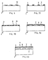
- FIGS. 1 and 9 to 13 illustrate various stages in the production of mold walls according to the invention.
- FIGS. 2 to 8 illustrate various stages in the production of known mold walls.
- multipartite molds are used to continuously cast steel slabs, steel beam blanks, steel blooms and steel strip.
- Such molds are made up of a number of separate mold walls, e.g., four mold walls, which are clamped to one another so as to define a casting cavity or passage.
- the numeral 1 identifies a carrier or support which is here in the form of a generally rectangular plate but could also take other forms depending upon the type of mold to be made.
- longitudinal cooling channels or slots 3 are machined in the major side 2 of the backup plate 1.
- the cooling channels 3, which are open at the major side 2 of the backup plate 1, can be made relatively shallow and wide in order to achieve high cooling efficiency. Due to the presence of the cooling channels 3, the major side 2 of the backup plate 1 serves as a heat-extracting side of the backup plate 1, and the backup plate 1 functions as a heat extracting backup plate.
- each of the cooling channels 3 is filled with a filler 4.
- the filler 4 consists of a material which will not run out of the cooling channels 3 as the backup plate 1 is manipulated for plating but which can be easily removed from the cooling channels 3 following plating.
- a preferred material for the filler 4 is wax.
- the filler 4 will generally be electrically nonconductive. Thus, as illustrated in FIG. 4, the filler 4 is coated with an electrical conductor 5 such as electrically conductive paint or electrically conductive tape.
- an electrical conductor 5 such as electrically conductive paint or electrically conductive tape.
- the heat-extracting side 2 of the backup plate 1 is now plated with a thermally conductive material, preferably copper.
- the plating operation can be carried out using conventional electroplating techniques. If desired, the sides of the backup plate 1 other than the heat-extracting side 2 can be masked to prevent deposition of the thermally conductive material.
- FIG. 5 shows the backup plate 1 with an electrodeposited layer or coating 6 of thermally conductive material.
- the layer 6 can, for example, have a thickness of 3/32 inch.
- a layer or coating 7 can be electroplated onto the thermally conductive layer 6 to serve as a base for a wear-resistant layer or coating 8 shown in FIG. 7. It is preferred for the base layer 7 to consist of nickel and for the wear-resistant layer 8 to consist of chromium, and the nickel and chromium can be applied in thicknesses customary for continuous casting molds.
- the wear-resistant layer 8 may be electrodeposited onto the base layer 7. Electrodeposition of the base layer 7 and the wear-resistant layer 8 may be performed using conventional techniques.
- the filler 4 is removed from the cooling channels 3. If the filler 4 is a material such as wax which melts at a temperature that does not affect the backup plate 1 or one of the layers 6,7,8, removal of the filler 4 from the cooling channels 3 can be accomplished by melting the filler 4. The filler 4 can then flow out of the cooling channels 3.
- the filler 4 is a material such as wax which melts at a temperature that does not affect the backup plate 1 or one of the layers 6,7,8, removal of the filler 4 from the cooling channels 3 can be accomplished by melting the filler 4. The filler 4 can then flow out of the cooling channels 3.
- the mold wall obtained when the filler 4 has been removed from the cooling channels 3 is identified by 9 in FIG. 8.
- the mold wall 9 can, for instance, be assembled with three other mold walls to form a continuous casting mold with a central casting cavity.
- the wear-resistant layer 8 of the mold 9 bounds one side of the casting cavity.
- the cooling channels 3 of the mold 9 are connected to a circulating water system in the usual manner so that the backup plate 1 can extract heat from a continuously cast strand formed in the casting cavity.
- the thermally conductive layer 6 can be relatively thin. This enables the cost of material to be reduced inasmuch as the thermally conductive layer 6 will normally consist of a high grade substance whereas the backup plate 1 can be made of a relatively low grade substance. Furthermore, by plating the thermally conductive layer 6 onto the backup plate 1, the invention eliminates the need to bolt the thermally conductive layer 6 to the backup plate 1. This is also of importance in holding down the thickness of the thermally conductive layer 6 because the thermally conductive layer 6 does not have to serve as an anchor for bolts.
- Machining of the cooling channels 3 into the backup plate 1 prior to plating greatly simplifies the production of the cooling channels 3 as opposed to drilling or boring through a solid body as in the prior art. Moreover, machining of the cooling channels 3 prior to plating permits the cooling channels 3 to be made relatively wide and shallow thereby allowing the cooling efficiency to be increased.
- the cooling channels 3 can be formed without machining.
- cores 10 constituting negatives of the cooling channels 3 are applied to the major side 2 of the backup plate 1 at the intended locations of the cooling channels 3. This is illustrated in Fig. 9.
- the widths and heights of the cores 10 correspond to the desired widths and depths of the cooling channels 3.
- the cores 10, which are preferably electrically non-conductive, may be adhesively secured to the backup plate 1.
- the cores 10 can, for instance, consist of plastic strips.
- thermally conductive material constituting part of the thermally conductive layer 6 is plated onto the major side 2 of the backup plate 1 around the cores 10.
- the plating operation is stopped.
- Fig. 10 shows the condition of the backup plate 1 at this time.
- the cores 10 are now removed as illustrated in Fig. 11 to form the cooling channels 3.
- the cooling channels 3 are filled with the filler 4 which is coated with the electrical conductor 5 as described previously.
- Plating of the thermally conductive material is resumed and continues until the thermally conductive layer 6 has been formed.
- the base layer 7 and wear resistant layer 8 are thereupon sequentially deposited over the thermally conductive layer 6 as outlined earlier.
- the filler 4 is removed from the cooling channels 3 to yield the mold wall 11 shown in Fig. 13.
- the invention can be used not only to produce new mold walls but also to refurbish used mold walls.
- the thermally conductive layer of a mold wall has been worn down to a predetermined thickness below which the mold wall should no longer be in service
- fresh thermally conductive material as well as a fresh base layer and a fresh wear-resistant layer, can be plated over the worn thermally conductive layer.
Landscapes
- Engineering & Computer Science (AREA)
- Mechanical Engineering (AREA)
- Manufacturing & Machinery (AREA)
- Continuous Casting (AREA)
- Electroplating Methods And Accessories (AREA)
- Moulds For Moulding Plastics Or The Like (AREA)
- Confectionery (AREA)
- Molds, Cores, And Manufacturing Methods Thereof (AREA)
Abstract
Description
Claims (10)
- A method of making a chilled mold wall, characterized in that a carrier (1) is provided, a core (10) is applied to the carrier (1), a thermally conductive material (6) is plated onto the carrier (1) in the regions of opposed locations of the core (10), and the core (10) is removed from the carrier (1) to thereby form a channel (3) running through the thermally conductive material (6).
- The method of claim 1, characterized in that a wear-resistant material is plated over the thermally conductive material.
- The method of claim 2, characterized in that a base material for the wear-resistant material is plated over the thermally conductive material and the wear-resistant material is plated over the base material.
- The method of claim 1, characterized in that plating of the thermally conductive material is interrupted before plating of the thermally conductive material has been completed and that the core is removed from the carrier after plating of the thermally conductive material has been interrupted, a filler being placed in the channel following removal of the core from the carrier and plating of the thermally conductive material being resumed after the filler is placed in the channel, the filler being removed from the channel after plating of the thermally conductive material has been completed.
- The method of claim 4, characterized in that plating of the thermally conductive material is interrupted when the thickness of the thermally conductive material equals or approximates the height of the core.
- The method of claim 4, characterized in that the filler is removed from the channel by causing the filler to flow out of the channel.
- The method of claim 1, characterized in that the thermally conductive material is electroplated onto the carrier.
- The method of claim 4, characterized in that the filler is coated with an electrical conductor prior to plating the thermally conductive material.
- The method of claim 4, characterized in that the filler is removed from the channel by melting the filler.
- The method of claim 3, characterized in that the thermally conductive material comprises copper, the base material comprises nickel, and the wear-resistant material comprises chromium.
Applications Claiming Priority (3)
| Application Number | Priority Date | Filing Date | Title |
|---|---|---|---|
| US08/538,624 US5716510A (en) | 1995-10-04 | 1995-10-04 | Method of making a continuous casting mold |
| US538624 | 1995-10-04 | ||
| PCT/US1996/016003 WO1997012708A1 (en) | 1995-10-04 | 1996-10-03 | Continuous casting mold and method of making |
Publications (3)
| Publication Number | Publication Date |
|---|---|
| EP0859674A1 EP0859674A1 (en) | 1998-08-26 |
| EP0859674A4 EP0859674A4 (en) | 1999-02-03 |
| EP0859674B1 true EP0859674B1 (en) | 2001-11-28 |
Family
ID=24147703
Family Applications (1)
| Application Number | Title | Priority Date | Filing Date |
|---|---|---|---|
| EP96933249A Expired - Lifetime EP0859674B1 (en) | 1995-10-04 | 1996-10-03 | Method of making a continuous casting mold |
Country Status (11)
| Country | Link |
|---|---|
| US (1) | US5716510A (en) |
| EP (1) | EP0859674B1 (en) |
| JP (1) | JP3023618B2 (en) |
| KR (1) | KR19990063997A (en) |
| AT (1) | ATE209543T1 (en) |
| AU (1) | AU7205796A (en) |
| CA (1) | CA2233703C (en) |
| DE (1) | DE69617451T2 (en) |
| ES (1) | ES2168126T3 (en) |
| MX (1) | MX9802572A (en) |
| WO (1) | WO1997012708A1 (en) |
Families Citing this family (10)
| Publication number | Priority date | Publication date | Assignee | Title |
|---|---|---|---|---|
| DE19852473C5 (en) * | 1998-11-13 | 2005-10-06 | Sms Demag Ag | Chill plate of a continuous casting plant |
| DE102004047533A1 (en) * | 2004-09-30 | 2006-04-06 | Carl Zeiss Smt Ag | Device for tempering elements |
| RU2308349C2 (en) * | 2005-11-10 | 2007-10-20 | Михаил Яковлевич Бровман | Method for manufacturing molds of machines for continuous casting of billets |
| DE102006037728A1 (en) * | 2006-08-11 | 2008-02-14 | Sms Demag Ag | Mold for the continuous casting of liquid metal, in particular of steel materials |
| US7451804B2 (en) * | 2006-11-22 | 2008-11-18 | Peterson Oren V | Method and apparatus for horizontal continuous metal casting in a sealed table caster |
| ITUD20130013A1 (en) * | 2013-02-01 | 2014-08-02 | Danieli Off Mecc | CRYSTALLIZER FOR CONTINUOUS CASTING AND METHOD FOR ITS REALIZATION |
| CN104357885A (en) * | 2014-10-15 | 2015-02-18 | 中航飞机股份有限公司西安飞机分公司 | Protection method for local chromium electroplating of shaft type part |
| KR101941506B1 (en) | 2014-10-28 | 2019-01-23 | 제이에프이 스틸 가부시키가이샤 | Continuous casting mold and method for continuous casting of steel |
| GB2596354B (en) * | 2020-06-26 | 2025-02-12 | Malondji Makango | Decorative artificial nail and method of manufacture |
| CN111842061B (en) * | 2020-08-07 | 2023-06-09 | 浙江盘毂动力科技有限公司 | Stator core and coating processing method thereof |
Family Cites Families (8)
| Publication number | Priority date | Publication date | Assignee | Title |
|---|---|---|---|---|
| GB1034473A (en) * | 1963-02-14 | 1966-06-29 | Davy & United Eng Co Ltd | Continuous casting |
| FR1476181A (en) * | 1966-04-15 | 1967-04-07 | Ts Nautchno I I Tchornoy Metal | Ingot mold for the continuous casting of metals, and method of manufacturing this mold |
| GB2100154B (en) * | 1981-04-27 | 1985-11-06 | Sumitomo Metal Ind | Molds for continuously casting steel |
| JPS59223143A (en) * | 1983-06-03 | 1984-12-14 | Oosakafu | Mold for continuous casting and its production |
| DE3522958C1 (en) * | 1985-06-27 | 1986-07-03 | Messerschmitt-Bölkow-Blohm GmbH, 8012 Ottobrunn | Process for the production of components such as heat exchangers, heat absorbers, rocket combustion chambers or the like. |
| JPH0659523B2 (en) * | 1988-09-09 | 1994-08-10 | ノムラテクノリサーチ株式会社 | Continuous casting mold manufacturing method |
| JPH02121752A (en) * | 1988-10-31 | 1990-05-09 | Kawasaki Steel Corp | Manufacture of mold for continuous casting |
| US5513691A (en) * | 1994-02-02 | 1996-05-07 | Sms Concast Inc. | Mold for continuous casting and method of making the mold |
-
1995
- 1995-10-04 US US08/538,624 patent/US5716510A/en not_active Expired - Fee Related
-
1996
- 1996-10-03 KR KR1019980702473A patent/KR19990063997A/en not_active Ceased
- 1996-10-03 JP JP9514499A patent/JP3023618B2/en not_active Expired - Fee Related
- 1996-10-03 DE DE69617451T patent/DE69617451T2/en not_active Expired - Lifetime
- 1996-10-03 ES ES96933249T patent/ES2168126T3/en not_active Expired - Lifetime
- 1996-10-03 EP EP96933249A patent/EP0859674B1/en not_active Expired - Lifetime
- 1996-10-03 AU AU72057/96A patent/AU7205796A/en not_active Abandoned
- 1996-10-03 AT AT96933249T patent/ATE209543T1/en active
- 1996-10-03 CA CA002233703A patent/CA2233703C/en not_active Expired - Fee Related
- 1996-10-03 WO PCT/US1996/016003 patent/WO1997012708A1/en not_active Ceased
-
1998
- 1998-04-02 MX MX9802572A patent/MX9802572A/en not_active Application Discontinuation
Also Published As
| Publication number | Publication date |
|---|---|
| KR19990063997A (en) | 1999-07-26 |
| CA2233703A1 (en) | 1997-04-10 |
| US5716510A (en) | 1998-02-10 |
| EP0859674A4 (en) | 1999-02-03 |
| DE69617451D1 (en) | 2002-01-10 |
| EP0859674A1 (en) | 1998-08-26 |
| AU7205796A (en) | 1997-04-28 |
| ES2168126T3 (en) | 2002-06-01 |
| WO1997012708A1 (en) | 1997-04-10 |
| ATE209543T1 (en) | 2001-12-15 |
| JP3023618B2 (en) | 2000-03-21 |
| MX9802572A (en) | 1998-11-29 |
| JPH11504571A (en) | 1999-04-27 |
| CA2233703C (en) | 2002-12-10 |
| DE69617451T2 (en) | 2002-08-14 |
Similar Documents
| Publication | Publication Date | Title |
|---|---|---|
| CA1067673A (en) | System for producing directionally solidified castings | |
| US5716510A (en) | Method of making a continuous casting mold | |
| US4669529A (en) | Continuous casting mould | |
| US5513691A (en) | Mold for continuous casting and method of making the mold | |
| US5108668A (en) | Process for manufacturing device for casting lead grids for electric battery plates | |
| US3059295A (en) | Composite mold for continuous casting | |
| WO1998041342A1 (en) | Improved continuous casting mold and method | |
| EP0052947B1 (en) | Casting mould | |
| US3937266A (en) | Method for application of wear-resistant coating | |
| CA1219727A (en) | One-piece, open-ended, water-cooled continuous casting mould and method of making the same | |
| CA2351081C (en) | Mold plate of a continuous casting plant | |
| US6340049B1 (en) | Device for casting of metal | |
| CA1102089A (en) | Electrolytic refining of metal | |
| US3554875A (en) | Method of fabricating a mandrel for electroforming | |
| EP0265174A3 (en) | Continuous casting molds | |
| CA1234475A (en) | Mold for producing grid plates for lead batteries | |
| JP2002505197A (en) | Metal casting equipment | |
| RU2149074C1 (en) | Method for continuous casting of thin flat metallic ingots | |
| JPS60174240A (en) | Casting wheel for rotary type continuous casting installation | |
| US4589469A (en) | Electrolytic refining of metal | |
| AU678696C (en) | Mold for continuous casting and method of making the mold | |
| US3860058A (en) | Method of forming dimensional holes in the wankel rotor housing electroform | |
| SU651891A1 (en) | Metallic casting mould manufacturing method | |
| JPH0112585B2 (en) | ||
| JPS5619956A (en) | Mold for continuous casting |
Legal Events
| Date | Code | Title | Description |
|---|---|---|---|
| PUAI | Public reference made under article 153(3) epc to a published international application that has entered the european phase |
Free format text: ORIGINAL CODE: 0009012 |
|
| 17P | Request for examination filed |
Effective date: 19980424 |
|
| AK | Designated contracting states |
Kind code of ref document: A1 Designated state(s): AT BE DE ES FI FR GB IT LU SE |
|
| A4 | Supplementary search report drawn up and despatched |
Effective date: 19981217 |
|
| AK | Designated contracting states |
Kind code of ref document: A4 Designated state(s): AT BE DE ES FI FR GB IT LU SE |
|
| 16A | New documents despatched to applicant after publication of the search report | ||
| RA4 | Supplementary search report drawn up and despatched (corrected) |
Effective date: 19981217 |
|
| 17Q | First examination report despatched |
Effective date: 20000324 |
|
| GRAG | Despatch of communication of intention to grant |
Free format text: ORIGINAL CODE: EPIDOS AGRA |
|
| RTI1 | Title (correction) |
Free format text: METHOD OF MAKING A CONTINUOUS CASTING MOLD |
|
| GRAG | Despatch of communication of intention to grant |
Free format text: ORIGINAL CODE: EPIDOS AGRA |
|
| GRAH | Despatch of communication of intention to grant a patent |
Free format text: ORIGINAL CODE: EPIDOS IGRA |
|
| GRAH | Despatch of communication of intention to grant a patent |
Free format text: ORIGINAL CODE: EPIDOS IGRA |
|
| GRAA | (expected) grant |
Free format text: ORIGINAL CODE: 0009210 |
|
| AK | Designated contracting states |
Kind code of ref document: B1 Designated state(s): AT BE DE ES FI FR GB IT LU SE |
|
| REF | Corresponds to: |
Ref document number: 209543 Country of ref document: AT Date of ref document: 20011215 Kind code of ref document: T |
|
| REG | Reference to a national code |
Ref country code: GB Ref legal event code: IF02 |
|
| REF | Corresponds to: |
Ref document number: 69617451 Country of ref document: DE Date of ref document: 20020110 |
|
| REG | Reference to a national code |
Ref country code: ES Ref legal event code: FG2A Ref document number: 2168126 Country of ref document: ES Kind code of ref document: T3 |
|
| PLBE | No opposition filed within time limit |
Free format text: ORIGINAL CODE: 0009261 |
|
| STAA | Information on the status of an ep patent application or granted ep patent |
Free format text: STATUS: NO OPPOSITION FILED WITHIN TIME LIMIT |
|
| 26N | No opposition filed | ||
| PGFP | Annual fee paid to national office [announced via postgrant information from national office to epo] |
Ref country code: FR Payment date: 20120403 Year of fee payment: 16 Ref country code: LU Payment date: 20120328 Year of fee payment: 16 |
|
| PGFP | Annual fee paid to national office [announced via postgrant information from national office to epo] |
Ref country code: DE Payment date: 20120323 Year of fee payment: 16 |
|
| PGFP | Annual fee paid to national office [announced via postgrant information from national office to epo] |
Ref country code: BE Payment date: 20120329 Year of fee payment: 16 Ref country code: GB Payment date: 20120322 Year of fee payment: 16 Ref country code: FI Payment date: 20120323 Year of fee payment: 16 Ref country code: SE Payment date: 20120322 Year of fee payment: 16 Ref country code: IT Payment date: 20120322 Year of fee payment: 16 |
|
| PGFP | Annual fee paid to national office [announced via postgrant information from national office to epo] |
Ref country code: AT Payment date: 20120323 Year of fee payment: 16 |
|
| BERE | Be: lapsed |
Owner name: SCHLOEMANN-SIEMAG INC. *SMS Effective date: 20121031 |
|
| REG | Reference to a national code |
Ref country code: AT Ref legal event code: MM01 Ref document number: 209543 Country of ref document: AT Kind code of ref document: T Effective date: 20121003 |
|
| GBPC | Gb: european patent ceased through non-payment of renewal fee |
Effective date: 20121003 |
|
| PGFP | Annual fee paid to national office [announced via postgrant information from national office to epo] |
Ref country code: ES Payment date: 20120327 Year of fee payment: 16 |
|
| REG | Reference to a national code |
Ref country code: FR Ref legal event code: ST Effective date: 20130628 |
|
| PG25 | Lapsed in a contracting state [announced via postgrant information from national office to epo] |
Ref country code: AT Free format text: LAPSE BECAUSE OF NON-PAYMENT OF DUE FEES Effective date: 20121003 Ref country code: SE Free format text: LAPSE BECAUSE OF NON-PAYMENT OF DUE FEES Effective date: 20121004 Ref country code: BE Free format text: LAPSE BECAUSE OF NON-PAYMENT OF DUE FEES Effective date: 20121031 Ref country code: DE Free format text: LAPSE BECAUSE OF NON-PAYMENT OF DUE FEES Effective date: 20130501 Ref country code: GB Free format text: LAPSE BECAUSE OF NON-PAYMENT OF DUE FEES Effective date: 20121003 |
|
| REG | Reference to a national code |
Ref country code: DE Ref legal event code: R119 Ref document number: 69617451 Country of ref document: DE Effective date: 20130501 |
|
| PG25 | Lapsed in a contracting state [announced via postgrant information from national office to epo] |
Ref country code: IT Free format text: LAPSE BECAUSE OF NON-PAYMENT OF DUE FEES Effective date: 20121003 Ref country code: FR Free format text: LAPSE BECAUSE OF NON-PAYMENT OF DUE FEES Effective date: 20121031 Ref country code: FI Free format text: LAPSE BECAUSE OF NON-PAYMENT OF DUE FEES Effective date: 20121003 |
|
| REG | Reference to a national code |
Ref country code: ES Ref legal event code: FD2A Effective date: 20140115 |
|
| PG25 | Lapsed in a contracting state [announced via postgrant information from national office to epo] |
Ref country code: ES Free format text: LAPSE BECAUSE OF NON-PAYMENT OF DUE FEES Effective date: 20121004 |
|
| PG25 | Lapsed in a contracting state [announced via postgrant information from national office to epo] |
Ref country code: LU Free format text: LAPSE BECAUSE OF NON-PAYMENT OF DUE FEES Effective date: 20121003 |