EP0859363A1 - Tape cassette - Google Patents
Tape cassette Download PDFInfo
- Publication number
- EP0859363A1 EP0859363A1 EP98106252A EP98106252A EP0859363A1 EP 0859363 A1 EP0859363 A1 EP 0859363A1 EP 98106252 A EP98106252 A EP 98106252A EP 98106252 A EP98106252 A EP 98106252A EP 0859363 A1 EP0859363 A1 EP 0859363A1
- Authority
- EP
- European Patent Office
- Prior art keywords
- lid
- connecting plate
- tape
- front lid
- rear lid
- Prior art date
- Legal status (The legal status is an assumption and is not a legal conclusion. Google has not performed a legal analysis and makes no representation as to the accuracy of the status listed.)
- Withdrawn
Links
- 238000003780 insertion Methods 0.000 claims description 3
- 230000037431 insertion Effects 0.000 claims description 3
- 238000004804 winding Methods 0.000 claims description 3
- 238000000034 method Methods 0.000 abstract description 8
- 239000000428 dust Substances 0.000 abstract description 6
- 238000010276 construction Methods 0.000 description 11
- 230000033001 locomotion Effects 0.000 description 4
- 239000011347 resin Substances 0.000 description 3
- 229920005989 resin Polymers 0.000 description 3
- 230000002093 peripheral effect Effects 0.000 description 2
- 230000000717 retained effect Effects 0.000 description 2
- 230000005611 electricity Effects 0.000 description 1
- 230000009545 invasion Effects 0.000 description 1
- 239000000463 material Substances 0.000 description 1
- 230000002787 reinforcement Effects 0.000 description 1
- 230000003068 static effect Effects 0.000 description 1
Images


Classifications
-
- G—PHYSICS
- G11—INFORMATION STORAGE
- G11B—INFORMATION STORAGE BASED ON RELATIVE MOVEMENT BETWEEN RECORD CARRIER AND TRANSDUCER
- G11B23/00—Record carriers not specific to the method of recording or reproducing; Accessories, e.g. containers, specially adapted for co-operation with the recording or reproducing apparatus ; Intermediate mediums; Apparatus or processes specially adapted for their manufacture
- G11B23/02—Containers; Storing means both adapted to cooperate with the recording or reproducing means
- G11B23/04—Magazines; Cassettes for webs or filaments
- G11B23/08—Magazines; Cassettes for webs or filaments for housing webs or filaments having two distinct ends
- G11B23/087—Magazines; Cassettes for webs or filaments for housing webs or filaments having two distinct ends using two different reels or cores
- G11B23/08707—Details
- G11B23/08735—Covers
Definitions
- the present invention relates to a tape cassette for use with a magnetic recording and/or reproducing apparatus.
- the present invention relates to a tape cassette having front and rear lids for protecting a magnetic tape against dust and having its rear lid suspended from the front lid by means of a connecting plate.
- a tape cassette to be used with a magnetic recording and/or reproducing apparatus such as a video tape recorder is exemplified by a VHS standard tape cassette having a tape width of 1/2 inch, or by an 8mm tape cassette having a tape width of 8 mm, as is well known in the prior art.
- Fig. 1(A) is a perspective view of the VHS standard tape cassette; and Fig. 1(B) is a side view for explaining a lid opening action of the VHS standard tape cassette.
- a VHS tape cassette 100 as shown in Figs. 1(A) and 1(B), is assembled from an upper half member 101 and a lower half member 102 into a box-shaped casing.
- This VHS standard tape cassette 100 is used to perform recording and/or reproducing operations by not-shown magnetic recording and/or reproducing apparatuses.
- the VHS standard tape cassette 100 has its external size and shape generally standardized to keep interchangeability with the apparatus.
- a magnetic tape T is made to move between a supply reel 103 and a take-up reel 104, which are disposed in the VHS standard tape cassette 100.
- the magnetic tape T wound on the supply reel 103 is guided around a supply side guide pole 105 and along a front lid 106 disposed at openings 102a of the lower half member 102 and is guided around a take-up side guide pole 107 so as to be taken-up on the take-up reel 104.
- the openings 102a 1 ⁇ 102a 3 of the lower half member 102 is opened at its bottom for permitting insertion of tape loading members (not-shown) of the apparatus.
- the front lid 106 is provided for protecting the magnetic face of the magnetic tape T against dust and finger-prints or the like.
- This front lid 106 is so supported at the right-hand and left-hand sides of the tape cassette 100 that it can be opened or closed on a pair of pins 106a and 106a (although only one is shown) integrated with the inner side of the right-hand and left-hand sides of the front lid 106.
- the front lid 106 is retained and closed by a front lid lock member 108 disposed at the left-hand side of the tape cassette 100.
- the front lid lock member 108 is released by a lid opening device of the apparatus so that the front lid 106 is opened on the pins 106a formed on the front lid 106, as indicated by double-dotted lines.
- an opening angle ⁇ 1 of the front lid 106 is not so large for a small-sized, lightweight portable apparatus but is sufficiently large for a large-sized tape deck or professional-use apparatus.
- the apparatus With the front lid 106 being opened, the apparatus is loaded with the magnetic tape T along its predetermined tape path by the (not-shown) tape loading members entered into the openings 102a 1 ⁇ 102a 3 .
- Fig. 2(A) is a perspective view of the 8 mm tape cassette of the prior art; and Fig. 2(B) is a side view for explaining a lid opening action of the 8 mm tape cassette.
- the 8 mm tape cassette 200 as shown in Fig. 2(A) and 2(B), has a construction substantially similar to the aforementioned one and is assembled of upper and lower half members 201 and 202 into a box-shaped casing, which is equipped therein with a supply reel 203 and a take-up reel 204 for causing the magnetic tape T to move.
- a rear lid 206 At an opening 202a provided on the lower half member 202 and at the back of a front lid 205, there is disposed a rear lid 206 for protecting the back face of the magnetic tape T, the side opposite to the magnetic tape.
- This 8 mm tape cassette 200 is disclosed in the Japanese Laid-Open Patent Publication No. 168979/1984.
- a brief description is given to the vicinity of the front lid 205 and the rear lid 206.
- the front lid 205 which is disposed at the side of the opening 202a of the lower half member 202, there is guided the magnetic tape T which is protected while being interposed between the front lid 205 and the rear lid 206.
- the front lid 205 is so supported at the right-hand and left-hand sides of the upper and lower half members 201 and 202 that it can be freely opened or closed on a pair of pins 205a and 205a formed integrally with the inner walls of the right-hand and left-hand sides thereof. From the middle portion of the front lid 205, on the other hand. there concurrently depend a pair of projections 205b and 205b, which rotatably support the generally "T-shaped" rear lid 206 such that the rear lid 206 can rotate by means of a pair of pins 206a and 206a integrated therewith.
- the front lid 205 and the rear lid 206 are opened together by a lid opening device of the apparatus, rotating around the supporting pins 205a formed on the front lid 205 which opens, as indicated by double-dotted lines.
- the rear lid 206 associatively with the opening action of the front lid 205 has to be opened to a position where the rear lid 206 is not contacted with the tape loading member for extracting the magnetic tape.
- a center of rotation of the rear lid 206 is in accordance with a common center line of the pair of pins 206a each projecting from a respective side thereof, thus, the rear lid 206 has only one phase in freedom of motion in the lid opening action, which requires the front lid to be opened largely.
- the magnetic tape T is required to undergo the recording and/or reproducing operations in a high density with excellent performance quality.
- the recording and reproducing operations can be digitally effected, the recording and/or reproducing qualities are apt to be seriously deteriorated if the magnetic tape T becomes dusty or is stained with fingerprints as well as foreign objects from the openings 102a 1 ⁇ 102a 3 .
- member corresponding to the disclosed rear lid (206) of the aforementioned 8 mm tape cassette 200 is attached to the VHS tape cassette 100.
- the not-shown magnetic recording and/or reproducing apparatus adopting the VHS tape cassette 100 has already been widely used in the relevant field. Considering the interchangeability between the VHS tape cassette 100 and the apparatus, the following problems (1) ⁇ (3) will arise to the users seriously, if the construction of the 8 mm tape cassette 200 is applied to the VHS tape cassette 100 as it is. Thus, it is difficult to adopt the member corresponding to the rear lid (206) into the existing construction.
- the rear lid opening/closing structure associated with the front lid have to be constructed so that the rear lid is connected to the front lid by means of the connecting plate not only to increase phases in freedom of motion but also to completely cover the back face of the magnetic tape with the rear lid together with the connecting plate. Further, when the rear lid is sufficiently opened associatively with the opening action of the front lid, the guide pins provided on the rear lid have to be prevented from coming off the open tops of the guide grooves.
- a general object of the present invention is to provide a novel and useful tape cassette in which the above disadvantage has been eliminated.
- a more specific object of the present invention is to provide a tape cassette having a casing for accommodating a pair of reels disposed in the casing for winding a magnetic tape on the pair of reels and threading the magnetic tape along a front of the casing, a front lid disposed in openable/closable manners at the front of the casing for protecting a front face of the magnetic tape and a rear lid disposed at a back side of the front lid for protecting a back face of the magnetic tape, wherein the tape cassette comprises, plate supporting means provided on an upper side of the front lid, a connecting plate having arm member means and first pin means for rotatably supporting the connecting plate on the plate supporting means of the front lid to protect an upper portion of the back face of the magnetic tape when the front lid is closed, the rear lid comprising second pin means and guide pin means for operating in cooperation with opening and closing actions of the front lid, the rear lid being suspended from the connecting plate by causing the second pin means to engage with the arm member means of the connecting plate to protect a lower portion of the back face
- Another specific object of the present invention is to provide a tape cassette having a casing comprising an upper half member and a lower half member for accommodating a pair of reels disposed in the casing for winding a magnetic tape on the pair of reels and threading the magnetic tape along opening means, a front lid disposed in openable/closable manners at the front of the casing for protecting a front face of the magnetic tape and a rear lid disposed at a back side of the front lid for protecting a back face of the magnetic tape, wherein said tape cassette comprises, the opening means defined in a front of the lower half member for allowing insertion of tape loading members of a recording and reproducing apparatus, and a pair of tape guides for guiding the magnetic tape therealong, the pair of tape guide projecting outwardly from a wall of the lower half member in the opening means in such a manner that the opening means is divided into three openings.
- tape cassette according to the present invention will be described in the following in connection with the embodiments thereof with reference to Figs. 3 to 8(C). This description will be made in detail individually for the embodiments in the order of the items of ⁇ Construction of Tape Cassette> and ⁇ Lid Opening Action of Tape Cassette>.
- Fig. 3 is a perspective view showing an entire construction of a tape cassette according to the present invention
- Fig. 4 is, partially broken, an exploded perspective view showing a front lid, a rear lid and a connecting plate together with their vicinity constituting essential parts of the tape cassette according to the present invention
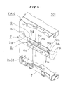
- Fig. 5 is a partially broken, an exploded perspective view showing a state where the rear lid and the connecting plate are attached to the front lid
- Fig. 6(A) is a cross-sectional view for explaining an assembly of main parts of the present invention, wherein the rear lid and the connecting plate are attached to the front lid
- Fig. 6(A) is a cross-sectional view for explaining an assembly of main parts of the present invention, wherein the rear lid and the connecting plate are attached to the front lid
- FIG. 6(B) is a cross-sectional view for explaining an assembly of main parts of the present invention, wherein the upper half member having the front lid is attached to an upper half member
- Fig. 6(C) is a cross-sectional view for explaining an assembly of main parts of the present invention, wherein the front lid is attached to a lower half member
- Fig. 7 is, partially broken, a partial perspective view showing, in an assembled state, the tape cassette where the front lid attached with the connecting plate and the rear lid is assembled into a casing.
- a tape cassette 301 of the present invention is halved into an upper half member 2 and a lower half member 3 of a resin material such that the upper half member 2 and the lower half member 3 are assembled into a box-shaped casing 1A.
- This casing 1A is equipped therein with a supply reel 4 and a take-up reel 5, between which a magnetic tape T is provided to move.
- the magnetic tape T wound on the supply reel 4 is guided, after having passed around a guide pole 6a (as clearly shown in Fig.
- the lower half member 3 is provided on its bottom: with holes 3b and 3c, which are aligned correspondingly with the supply reel 4 and the take-up reel 5: with positioning holes 3d and 3e located in the vicinity of the opening 3a for positioning the tape cassette 301 in the apparatus: and with a hole 3f for accepting a light emitting element (not-shown) for detecting the loaded state of the magnetic tape T.
- the aforementioned front lid 7 provided at a front of casing 1A is supported in openable and closable manners on the left-hand and right-hand sides 3g and 3h of the casing 1A by means of a pair of pins 7a 1 and 7b 1 (although only the pin 7a 1 is explicitly shown) which are formed integrally with the inner walls of the right-hand and left-hand sides 7a and 7b of the front lid 7.
- the front lid 7 is retained by a front lid lock member 12 which is disposed on the left-hand side 3g of the lower half member 3, so that it is kept to be closed state.
- the opening action of the front lid 7 is allowed only when the tape cassette 301 is loaded into the (not-shown) magnetic recording and/or reproducing apparatus.
- the front lid lock member 12 is released by a lid opening device of the apparatus to allow the front lid 7 to be opened, but a detailed description is omitted here.
- the aforementioned rear lid 8 is suspended from a connecting plate 9 provided on the front lid 7 in such manners that both the rear lid 8 and the connecting plate 9 oppose a back face of the magnetic tape T which is extendingly interposed between the front lid 7 and the rear lid 8 connected to the connecting plate 9 along the back of the front lid 7.
- These rear lid 8 and the connecting plate 9 are integrally operable in openable and closable manners in cooperation with the front lid 7.
- the rear lid 8 and the connecting plate 9 protect the back face of the magnetic tape T against the dust invading from the openings 3a 1 ⁇ 3a 3 provided on the lower half member 3. They further protect the magnetic tape T itself from being scratched by fingers or foreign objects which may come through the opening 3a.
- the above mentioned tape cassette 301 of the present invention is constructed to keep an interchangeability with an industry standard VHS tape cassette, however, it is not limited to the standard VHS tape cassette but is adaptable to any kinds of tape cassettes having moderate size configurations.
- the upper half member 2 and the lower half member 3 are individually formed and are separated at a height H 2 from a bottom of the lower half member 3, which is about one half of the height H 1 of the front lid 7 being substantially equal to that of the tape cassette 301.
- the upper half member 2 is protrudingly formed with front rims 2a 1 , 2a 2 , each having a thin thickness, being separated each other at a predetermined distance at the front thereof.
- the front rims 2a 1 , 2a 2 are respectively provided with engagement recess 2a 11 , 2a 21 (explicitly shown in Fig. 6(B))at bottoms thereof.
- the engagement recesses 2a 11 , 2a 21 are respectively connected to open tops of guide grooves 3p 1 , 3q 1 provided in protruding portions 3p, 3q of the lower half member 3 as described hereafter.
- the assembly of the tape cassette is made easy, in particular, when the upper half member 2 temporarily assembled with the front lid 7 provided with the rear lid 8, is attached to the lower half member 3 as described hereafter.
- a guide 2a 3 for guiding the connecting plate 9 is protrudingly formed in a tapered shape in front of the upper half member 2 between the left-hand and the right-hand front rims 2a 1 , 2a 2 .
- the guide 2a 3 is detachably contacted with a cam 9a provided at a back surface of the connecting plate 9 supported by the front lid 7.
- the connecting plate 9 When the front lid 7 is closed by a biasing force of a first biasing member 10 (referred to as torsion spring 10) provided on a pin 7a 1 of the front lid 7 for biasing the front lid 7 in a lid closing direction, the connecting plate 9 is biased in a lid opening direction by a second biasing member 11 (referred to as torsion spring 11) for biasing the connecting plate 9 in a direction of the bottom of an upper plate 7d provided in the front lid 7, i.e., in a clockwise direction, however, the connecting plate 9 is restricted to move and keeps a closed state against the biasing force of the torsion spring 11 by causing the cam 9a thereof to abut on the guide 2a 3 of the upper half member 2.
- the rear lid 8 suspended from the connecting plate 9 is also biased in the lid opening direction by the torsion spring 11, but keeps a closed state subjected to the action of the connecting plate 9 against the torsion spring 11 as well.
- the guide 2a 3 of the upper half member 2 and the cam 9a of the connecting plate 9 constitute a rear lid restricting tool for restricting the opening action of the rear lid 8 connected to the connecting plate 9 when the front lid 7 is closed.
- front portions of the left-hand and right-hand sides 3g, 3h of the lower half member 3 respectively have a height H 3 slightly lower than the height H 1 of the front lid 7 and the rear portions of the left-hand and right-hand sides 3g, 3h have a height H 2 .
- the upper half and lower half members 2, 3 are assembled into the casing 1A supporting the front lid 7 thereby, as follows.
- the front lid 7 is supported by the upper half member 2 by causing the pins 7a 1 , 7b 1 of the front lid 7 to be inserted into holes 2g 1 , 2h 1 having open ends each defined at the left side 2g and the right side 2h of the upper half member 2.
- the upper half member 2 is assembled into the casing 1A by causing peripheral portions thereof to abut on peripheral portions of the lower half member 3.
- the front lid 7 is supported in the openable and closable manners in front of the casing 1A thereby.
- tape guides 3i, 3j projecting from a wall of the lower half member 3 for guiding the magnetic tape T are protrudingly and integrally provided in a plate shape separated at a predetermined distance.
- These tape guides 3i, 3j are slightly higher than the height H 2 of the lower half member 3.
- These tape guides 3i, 3j have a function to prevent the magnetic tape T from being closely contacted with the rear lid 8 and the connecting plate 9 due to static electricity.
- these tape guides 3i, 3j are defined with recesses 3m, 3n therebehind to cause cutouts 8c 1 , 8c 2 formed in the rear lid 8 to mount therein as described hereafter,
- these tape guide 3i, 3j are provided with tape guide rims 3i 1 , 3j 1 at lower ends thereof for preventing the magnetic tape T from slipping off from the tape guides 3i, 3j.
- the tape guides 3i, 3j are integrally provided with a pair of protruding portions 3p and 3q therebehind, respectively, in conjunction with the recesses 3m, 3n so that the paired protruding portions protrude upward to have a height H 3 slightly lower than the height H 1 of the front lid 7.
- the paired protruding portions 3p, 3q are provided with a pair of opposing guide portions 3p 1 and 3q 1 (as will be referred to as the "guide grooves") which are "boot-shaped" grooves each having an open top in the lid opening direction and a closed bottom in the lid closing direction, respectively.
- guide grooves there can be snugly and slidably fitted (in engagement) guide pins 8d 1 and 8d 2 which are formed on the rear lid 8.
- the rear lid 8 of the present invention is easily assembled into the tape cassette 301, thanks to the provision of the open top of the paired guide grooves 3p 1 , 3q 1 , and is sufficiently opened in operation without slipping off from the paired guide grooves 3p 1 , 3q 1 and the front rims 2a 1 , 2a 2 of the upper half member 2 for coverring the open tops.
- the guide grooves 3p 1 , 3q 1 for guiding the guide pins 8d 1 , 8d 2 are provided nearby innermost portions of the opening 3a 2 defined approximately in front of the center of the lower half member 3, thus, the lid opening and closing operations can be performed without disturbing the tape loading members of the apparatus by causing the rear lid 8 and the connecting plate 9 to be kept parallel to the front lid 7.
- the lower half member 3 is defined with holes 3r, 3s for installing the guide poles 6a, 6b shown in Fig. 7.
- the magnetic tape T is extendingly disposed between the guide poles 6a, 6b fitted in the holes 3r, 3s as shown with double-dotted lines.
- the front lid 7 is provided with a front plate 7c connected vertically to the upper plate 7d downward between a left-hand plate 7a and a right-hand plate 7b thereof, forming an "inverted L-shape" in cross section, and the front plate 7c has its lower end slightly extended backward to form a triangular (sectional view) portion 7c 1 .
- the triangular portion 7c 1 has a function to cover the lower end of the magnetic tape T, which is disposed along the back surface of the front lid 7, in a sealed state together with a later-described lower end portion 8b 1 of the rear lid 8, when the front lid 7 is closed.
- the triangular portion 7c 1 protects the magnetic tape T in a state isolated from the openings 3a 1 ⁇ 3a 3 .
- connecting plate supporting portions 7d 1 , 7d 2 (as will be referred to as the "plate supporting portion 7d 1 , 7d 2 ") separated at a predetermined distance.
- the plate supporting portions 7d 1 , 7d 2 are defined with holes 7d 11 , 7d 21 , respectively, for rotatably supporting the connecting plate 9.
- the connecting plate 9 of the main part of the present invention is disposed under the bottom of the upper plate 7d of the front lid 7 and has a function to protect the upper portion of the back face of the magnetic tape T disposed along the back surface of the front lid 7 by coverring it.
- the connecting plate 9 made of resin is formed so as to have a width approximately same to that of the rear lid 8, and so as to have an "inverted L-shape" at the front 9b opposite to the back surface of the front lid 7.
- the aforementioned cam 9a projects from the back surface of the connecting plate 9, and a pair of left-hand and right-hand pins 9c 1 , 9c 2 are integrally provided with at a wall of a hollow mass portion which defines a hollow portion and with a distal end of the connecting plate 9, respectively, so as to face horizontally in a right direction.
- the connecting plate 9 can be rotatably and horizontally supported by the front lid 7 along the back surface of the front lid 7 by causing the left-hand pin 9c 1 with a torsion spring 11 to be inserted into the hole 7d 11 of the plate supporting portion 7d 1 and by causing the right-hand pin 9c 2 to be inserted into the hole 7d 21 of the plate supporting portion 7d 2 .
- the torsion spring 11 forces the connecting plate 9 in the bottom surface direction of the upper plate 7d of the front lid 7 and the rear lid 8 suspended from the connecting plate 9 in the lid opening direction.
- a reinforcement frame having an "U" letter-shape is provided around the hollow mass portion of the connecting plate 9.
- an arms 9d 1 is protrudingly provided in a slant downward direction from a wall of a left-hand cutout and an arm 9d 2 is provided in the same manner at a right-hand distal end, of the connecting plate 9.
- the arms 9d 1 and 9d 2 are respectively formed with holes 9d 11 , 9d 21 , horizontally.
- the rear lid 8 is suspended from the arms 9d 1 , 9d 2 by causing the pins 8a 1 , 8a 2 thereof to be inserted into the abovementioned holes 9d 11 , 9d 21 .
- the rear lid 8 of the present invention has a function to protect the back face and the under portion of the magnetic tape T disposed along the back surface of the front lid 7 by covering the under portion thereof.
- the above rear lid 8 is formed by using resin to have an enough length in a longitudinal direction to cover the openings 3a 1 ⁇ 3a 3 at a lower portion thereof by causing the lower portion to be inserted into the openings 3a 1 ⁇ 3a 3 , and a front side 8b of the rear lid 8 facing to the back surface of the front lid 7 has an inverted L letter-shape in a height direction.
- a pair of pins 8a 1 , 8a 2 project horizontally in the inverted L-shape from the upper portion nearby both sides of the rear lid 8.
- the rear lid 8 is rotatably suspended from the connecting plate 9 by causing the paired pins 8a 1 , 8a 2 to be inserted into the holes 9d 11 , 9d 21 of the arms 9d 1 , 9d 2 provided on the connecting plate 9.
- a pair of cutouts 8c 1 , 8c 2 are formed at an under portion of the rear lid 8 separated at a predetermined distance, and each of the guide pins 8d 1 , 8d 2 protrudes horizontally in an opposite direction from a wall of the respective cutouts 8c 1 , 8c 2 .
- pins 8d 1 , 8d 2 are slidably fitted with the guide grooves 3p 1 , 3q 1 , respectively, formed in the protruding portions 3p, 3q of the lower half member 3 as mentioned in the foregoing.
- parts of the cutouts 8c 1 , 8c 2 of the rear lid 8 are formed to be allowed to freely enter into the recesses 3m, 3n of the lower half member 3 without abutting thereon.
- the lower end portion 8b 1 except for the cutouts 8c 1 , 8c 2 protects the lower portion of the magnetic tape T in a wrapping manner by abutting on the inner wall of the triangle portion 7c 1 of the front lid 7.
- the rear lid 8 when the rear lid 8 is connected to the front lid 7 by using the connecting plate 9, the rear lid 8 is rotated on the two pairs of rotating pins consisting of the paired pins (9c 1 , 9c 2 ) connecting the connecting plate 9 to the front lid 7 and the paired pins (8a 1 , 8a 2 ) connecting the connecting plate 9 to the rear lid 8, thus, the rear lid 8 has two degrees of freedom of motion in link mechanism, which enables the connecting plate 9 and the rear lid 8 to be opened and closed smoothly parallel to the front lid 7 in cooperation with the font lid 7.
- the torsion spring 10 is inserted into the the pin 7a 1 of the front lid 7.
- the connecting plate 9 is rotatably supported on the front lid 7 by causing the pin 9c 1 to be supported with plate supporting portion 7d 1 of the front lid 7.
- the rear lid 8 is suspended from the connecting plate 9 by causing the pin 8a 1 of the rear lid 8 to be supported with the arm 9d 1 of the connecting plate 9, thus the rear lid 8 is connected to the front lid by means of the connecting plate 9.
- the front lid 7 is temporarily assembled to the upper half member 2.
- the front lid 7 is temporarily fabricated to the upper half member 2 by causing the guide pin 8d 1 of the rear lid 8 to be engaged with the engagement recess 2a 11 of the upper half member 2 manually.
- the upper half member 2 is assembled to the lower half member 3 keeping a state where the guide pin 8d 1 is engaged with the engagement recess 2a 11 .
- the upper half member 2 carrying the front lid 7 and the rear lid 8 in a lid opened state is safely and securely assembled to the lower half member 3 without causing the front and rear lids 7, 8 to contact with the magnetic tape T.
- the front rim 2a 1 of the upper half member 2 abuts on the upper end portion of the protruding portion 3p, connecting the engagement recess 2a 11 to the open top of the guide groove 3p 1 . Therefore, the guide pin 8d 1 of the rear lid 8 is guided by the guide groove 3p 1 without coming off from the open top of the guide groove 3p 1 , which enables a speedy and secure assembly to be performed and contributes to increase reliability and quality of the tape cassette 301.
- the magnetic tape T is extended along the tape guides 3i, 3j from the guide pole 6a of the supply side to the guide pole 6b of the take-up side.
- the front face of the magnetic tape T is protected by being covered with the front lid 7 and the upper and lower portions of the rear face thereof are respectively protected by being covered with the connecting plate 9 and the rear lid 8.
- connection plate 9 rotational movement of the connecting plate 9 is restricted by the cam 9a provided at the back surface of the connecting plate 9 to abut on the guide 2a 3 protrudingly provided on the upper half member 2 in the tapered shape, so that the connecting plate 9 is held in a closed state against the biasing force of the torsion spring 11.
- the guide pins 8d 1 , 8d 2 of the rear lid 8 suspended from the connecting plate 9 come to the lower ends of the guide grooves 3p 1 , 3q 1 of the protruding portions 3p, 3q provided on the lower half member 3, and the rear lid 8 is held in the closed state by being subjected to the closed state of the connecting plate 9.
- the rear lid 8 and the connecting plate 9 are prevented from displacing in the right and left directions toward the front lid 7 by being connected to one another.
- Fig. 8(A) is a cross-sectional view for explaining lid opening and closing actions of the tape cassette, wherein the front lid, the rear lid and the connecting plate are closed
- Fig. 8(B) is a cross-sectional view for explaining lid opening and closing actions of the tape cassette, wherein the front lid, the rear lid and the connecting plate are on the way to the opening state
- Fig. 8(C) is a cross-sectional view for explaining lid opening and closing actions of the tape cassette, wherein the front lid is fully opened, and the pin 8d 1 of the rear lid comes to the open top of the guide groove of the lower half member.
- FIG. 8(A) A state shown in Fig. 8(A) is identical to one shown in Fig.7 where the front lid 7 is closed, and the magnetic tape T is extended along the back surface of the front lid 7. Further, the connecting plate 9 is rotatably supported on the plate supporting portion 7d 1 of the front lid 7 therebehind by causing the pin 9c 1 thereof to be engaged, and the rear lid 8 is suspended from the arm 9d 1 of the connecting plate 9 by causing the pin 8a 1 of the rear lid 8 to be engaged, and the front lid 7 is biased in the lid closed direction with the torsion spring 10.
- the guide pin 8d 1 provided nearby the under portion of the rear lid 8 comes to the closed end of the guide groove 3p 1 formed in the protruding portion 3p of the lower half member 3 being engaged with the guide groove 3p 1 .
- the rear lid 8 protects the lower portion of the magnetic tape T against dust and the fingerprint from the openings 3a 1 ⁇ 3a 3 (Fig. 7) in a wrapping manner by causing the lower end portion 8b 1 of the rear lid 8 to abut on the inner wall of the triangle portion 7c 1 of the front lid 7.
- the magnetic tape T Since the front face of the magnetic tape T is protected with the front lid 7, and the upper and lower portions of the back face thereof are respectively protected with the connecting plate 9 and the rear lid 8, thus the magnetic tape T is completely protected when the front lid 7 is closed, i.e., when it is not used.
- connecting plate 9 is restricted to be held in the closed state against the biasing force of the torsion spring 11 by causing the cam 9a thereof to abut on the guide 2a 3 protrudingly provided in the tapered shape on the upper half member 2.
- the front lid 7 is rotated to open in a clockwise direction (an arrow direction) on the pins 7a 1 , 7b 1 of the front lid 7.
- the connecting plate 9 is displaced upward by causing the cam 9a provided at back surface of the connecting plate 9 to be abutting on the guide 2a 3 of the upper half member 2, whereby the rear lid 8 suspended from the connecting plate 9 is displaced upward by being pivoted with the pin 8a 1 thereof, thus, the guide pin 8d 1 provided on the rear lid 8 is displaced upward along the guide groove 3p 1 .
- the rear lid 8 suspended from the connecting plate 9 is opened in cooperation with the opening action of the front lid 7.
- the rear lid 8 can be smoothly opened parallel to the front lid 7 because of achieving two phases of freedom in the link mechanism.
- the triangle portion 7c 1 of the front lid 7 recedes from the front face of the magnetic tape T
- the rear lid 8 is opened so that the lower end portion 8b 1 of the rear lid 8 is kept away from contacting with the back face of the magnetic tape T because the guide pin 8d 1 of the rear lid 8 is guided in the guide groove 3p 1 .
- the guide pin 8d 1 provided on the rear lid 8 is prevented from coming off the guide groove 3p 1 upward by the front rim 2a 1 of the upper half member 2.
- the front and rear lids 7, 8 to open sufficiently, which contributes to improve the reliability and quality of the tape cassette 301.
- the tape cassette 301 when the tape cassette 301 is not mounted on the recording and/or reproducing apparatus, the front face of the magnetic tape extended along the back surface of the front lid is protected by the front lid, and the upper and lower portions of the back face of the magnetic tape are respectively protected by the connecting plate and the rear lid, thus the magnetic tape is completely protected against invasion of dust and fingerprints and further against foreign objects.
- the rear lid is more easily opened and closed parallel to the front lid because the rear lid suspended by the front lid through the connecting plate is given a more degree of freedom, i.e., 2 degrees of freedom based on a pivot point between the front lid and the connecting plate, and another pivot point between the connecting plate and the rear lid, compared with the foregoing prior art such as 8 mm tape cassette wherein the rear lid is directly suspended on the front lid.
- the pin of the rear lid is guided by the guide groove of which the top open end is covered with the engagement recess, so that the pin is prevented from coming off from the open top of the guide groove, which enables a speedy and secure assembly to be performed and contributes to increase reliability and quality of the tape cassette 301.
Landscapes
- Packaging Of Annular Or Rod-Shaped Articles, Wearing Apparel, Cassettes, Or The Like (AREA)
Abstract
The present invention discloses a tape cassette having a
front lid for protecting a magnetic face of a magnetic tape
accommodated in a casing made of upper and lower half
members against dust or the like, and a connecting plate
and a rear lid suspended from the connecting plate for
protecting an upper portion and a lower portion of the rear
face of the magnetic tape respectively. The front lid is
rotatably supported at sides of the casing. The rear lid is
rotatably suspended on the connecting plate which is rotatably
supported on the front lid. The magnetic tape is
protected between the front lid and the rear lids together
with the connecting plate in a lid closed state. A pair of
pins provided on the rear lid is snugly fitted in a pair of
guide grooves formed in protruding portions provided in the
lower half member so that the rear lid may move in opening
and closing directions. The guide grooves have open tops so
that the pins of the rear lid are easily inserted into the
guide grooves in the assembly process. The open tops are
covered with front rims provided on the upper half member in
the assembly process.
Description
The present invention relates to a tape cassette for use
with a magnetic recording and/or reproducing apparatus.
Particularly, the present invention
relates to a tape cassette having front and rear lids for
protecting a magnetic tape against dust and having its rear
lid suspended from the front lid by means of a connecting
plate.
A tape cassette to be used with a magnetic recording
and/or reproducing apparatus such as a video tape recorder
is exemplified by a VHS standard tape cassette having a tape
width of 1/2 inch, or by an 8mm tape cassette having a tape
width of 8 mm, as is well known in the prior art.
Fig. 1(A) is a perspective view of the VHS standard tape
cassette; and Fig. 1(B) is a side view for explaining a lid
opening action of the VHS standard tape cassette.
A VHS tape cassette 100, as shown in Figs. 1(A) and
1(B), is assembled from an upper half member 101 and a lower
half member 102 into a box-shaped casing. This VHS standard
tape cassette 100 is used to perform recording and/or
reproducing operations by not-shown magnetic recording
and/or reproducing apparatuses. For these operations, the
VHS standard tape cassette 100 has its external size and
shape generally standardized to keep interchangeability with
the apparatus.
Moreover, a magnetic tape T is made to move between a
supply reel 103 and a take-up reel 104, which are disposed
in the VHS standard tape cassette 100. The magnetic tape T
wound on the supply reel 103 is guided around a supply side
guide pole 105 and along a front lid 106 disposed at
openings 102a of the lower half member 102 and is guided
around a take-up side guide pole 107 so as to be taken-up on
the take-up reel 104.
The openings 102a1∼102a3 of the lower half member 102 is
opened at its bottom for permitting insertion of tape
loading members (not-shown) of the apparatus.
On the other hand, the front lid 106 is provided for
protecting the magnetic face of the magnetic tape T against
dust and finger-prints or the like. This front lid 106 is so
supported at the right-hand and left-hand sides of the tape
cassette 100 that it can be opened or closed on a pair of
pins 106a and 106a (although only one is shown) integrated
with the inner side of the right-hand and left-hand sides
of the front lid 106. However, the front lid 106 is retained
and closed by a front lid lock member 108 disposed at the
left-hand side of the tape cassette 100.
Referring to Fig. 1(B), only when the VHS standard tape
cassette 100 is inserted into the magnetic recording and/or
reproducing apparatus, the front lid lock member 108 is
released by a lid opening device of the apparatus so that
the front lid 106 is opened on the pins 106a formed on the
front lid 106, as indicated by double-dotted lines. At this
time, an opening angle 1 of the front lid 106 is not so
large for a small-sized, lightweight portable apparatus but
is sufficiently large for a large-sized tape deck or
professional-use apparatus.
With the front lid 106 being opened, the apparatus is
loaded with the magnetic tape T along its predetermined tape
path by the (not-shown) tape loading members entered into
the openings 102a1∼102a3.
Fig. 2(A) is a perspective view of the 8 mm tape
cassette of the prior art; and Fig. 2(B) is a side view for
explaining a lid opening action of the 8 mm tape cassette.
On the other hand, the 8 mm tape cassette 200 as shown
in Fig. 2(A) and 2(B), has a construction substantially
similar to the aforementioned one and is assembled of upper
and lower half members 201 and 202 into a box-shaped casing,
which is equipped therein with a supply reel 203 and a
take-up reel 204 for causing the magnetic tape T to move. At
an opening 202a provided on the lower half member 202 and at
the back of a front lid 205, there is disposed a rear lid
206 for protecting the back face of the magnetic tape T, the
side opposite to the magnetic tape.
This 8 mm tape cassette 200 is disclosed in the Japanese
Laid-Open Patent Publication No. 168979/1984. Here, a brief
description is given to the vicinity of the front lid 205
and the rear lid 206. Along the front lid 205 which is
disposed at the side of the opening 202a of the lower half
member 202, there is guided the magnetic tape T which is
protected while being interposed between the front lid 205
and the rear lid 206.
Specifically, the front lid 205 is so supported at the
right-hand and left-hand sides of the upper and lower half
members 201 and 202 that it can be freely opened or closed
on a pair of pins 205a and 205a formed integrally with the
inner walls of the right-hand and left-hand sides thereof.
From the middle portion of the front lid 205, on the other
hand. there concurrently depend a pair of projections 205b
and 205b, which rotatably support the generally "T-shaped"
rear lid 206 such that the rear lid 206 can rotate by means
of a pair of pins 206a and 206a integrated therewith.
From the lower ends of the right-hand and left-hand
sides of the rear lid 206, there are concurrently
projected a pair of guide pins 206b and 206b. These guide
pins 206b and 206b are fitted in a pair of guide grooves
202b and 202b which are formed in the right-hand and left-hand
sides of the opening 202a of the lower half member 202.
Only when a not-shown magnetic recording and/or
reproducing apparatus is loaded with the 8mm tape cassette
200, as shown in Fig. 2(B), the front lid 205 and the rear
lid 206 are opened together by a lid opening device of the
apparatus, rotating around the supporting pins 205a formed
on the front lid 205 which opens, as indicated by double-dotted
lines.
Here, the rear lid 206 associatively with the opening
action of the front lid 205 has to be opened to a position
where the rear lid 206 is not contacted with the tape
loading member for extracting the magnetic tape. However, a
center of rotation of the rear lid 206 is in accordance with
a common center line of the pair of pins 206a each
projecting from a respective side thereof, thus, the rear
lid 206 has only one phase in freedom of motion in the lid
opening action, which requires the front lid to be opened
largely.
In recent years, the magnetic tape T is required to
undergo the recording and/or reproducing operations in a
high density with excellent performance quality. At the
present stage, moreover, the recording and reproducing
operations can be digitally effected, the recording and/or
reproducing qualities are apt to be seriously deteriorated
if the magnetic tape T becomes dusty or is stained with
fingerprints as well as foreign objects from the openings
102a1∼102a3.
It is, therefore, considered that member corresponding
to the disclosed rear lid (206) of the aforementioned 8 mm
tape cassette 200 is attached to the VHS tape cassette 100.
However, the not-shown magnetic recording and/or reproducing
apparatus adopting the VHS tape cassette 100 has already
been widely used in the relevant field. Considering the
interchangeability between the VHS tape cassette 100 and the
apparatus, the following problems (1)∼(3) will arise to the
users seriously, if the construction of the 8 mm tape
cassette 200 is applied to the VHS tape cassette 100 as it
is. Thus, it is difficult to adopt the member corresponding
to the rear lid (206) into the existing construction.
In summary, the rear lid opening/closing structure
associated with the front lid have to be constructed so
that the rear lid is connected to the front lid by means of
the connecting plate not only to increase phases in freedom
of motion but also to completely cover the back face of the
magnetic tape with the rear lid together with the connecting
plate. Further, when the rear lid is sufficiently opened
associatively with the opening action of the front lid, the
guide pins provided on the rear lid have to be prevented
from coming off the open tops of the guide grooves.
Furthermore, in the assembly process, when the upper half
member temporarily fabricated with front lid provided with
the rear lid by means of the connecting plate is assembled
into the casing, the guide pins of the rear lid have to be
securely fitted in the guide grooves in efficient manners
without contacting with the magnetic tape, no matter how
much its external shape might be different. Thus, there has
been desired a tape cassette which can satisfy those
conditions.
Accordingly, a general object of the present invention
is to provide a novel and useful tape cassette in which the
above disadvantage has been eliminated.
A more specific object of the present invention is to
provide a tape cassette having a casing for accommodating a
pair of reels disposed in the casing for winding a magnetic
tape on the pair of reels and threading the magnetic tape
along a front of the casing, a front lid disposed in
openable/closable manners at the front of the casing for
protecting a front face of the magnetic tape and a rear lid
disposed at a back side of the front lid for protecting a
back face of the magnetic tape, wherein the tape cassette
comprises, plate supporting means provided on an upper side
of the front lid, a connecting plate having arm member means
and first pin means for rotatably supporting the connecting
plate on the plate supporting means of the front lid to
protect an upper portion of the back face of the magnetic
tape when the front lid is closed, the rear lid comprising
second pin means and guide pin means for operating in
cooperation with opening and closing actions of the front
lid, the rear lid being suspended from the connecting plate
by causing the second pin means to engage with the arm
member means of the connecting plate to protect a lower
portion of the back face of the magnetic tape, guide groove
means provided in the casing for slidably guiding the guide
pin means in the lid opening and closing directions by
being engaged with the guide pin means of the rear lid,
first biasing means for biasing the front lid in lid
opening direction, second biasing means for displacing the
rear lid in the lid opening direction by biasing the
connecting plate toward a direction of the upper side of
the front lid, and rear lid restricting means for
restricting an opening action of the rear lid biased in the
lid opening direction by the second biasing means when the
front lid is closed.
Another specific object of the present invention is to
provide a tape cassette having a casing comprising an upper
half member and a lower half member for accommodating a
pair of reels disposed in the casing for winding a magnetic
tape on the pair of reels and threading the magnetic tape
along opening means, a front lid disposed in openable/closable
manners at the front of the casing for protecting a
front face of the magnetic tape and a rear lid disposed at
a back side of the front lid for protecting a back face of
the magnetic tape, wherein said tape cassette comprises, the
opening means defined in a front of the lower half member
for allowing insertion of tape loading members of a recording
and reproducing apparatus, and a pair of tape guides
for guiding the magnetic tape therealong, the pair of tape
guide projecting outwardly from a wall of the lower half
member in the opening means in such a manner that the
opening means is divided into three openings.
The tape cassette according to the present invention
will be described in the following in connection with the
embodiments thereof with reference to Figs. 3 to 8(C). This
description will be made in detail individually for the
embodiments in the order of the items of <Construction of
Tape Cassette> and <Lid Opening Action of Tape Cassette>.
Fig. 3 is a perspective view showing an entire construction
of a tape cassette according to the present
invention; Fig. 4 is, partially broken, an exploded perspective
view showing a front lid, a rear lid and a connecting
plate together with their vicinity constituting essential
parts of the tape cassette according to the present
invention; Fig. 5 is a partially broken, an exploded
perspective view showing a state where the rear lid and the
connecting plate are attached to the front lid; Fig. 6(A) is
a cross-sectional view for explaining an assembly of main
parts of the present invention, wherein the rear lid and the
connecting plate are attached to the front lid; Fig. 6(B) is
a cross-sectional view for explaining an assembly of main
parts of the present invention, wherein the upper half
member having the front lid is attached to an upper half
member; Fig. 6(C) is a cross-sectional view for explaining
an assembly of main parts of the present invention, wherein
the front lid is attached to a lower half member; and Fig. 7
is, partially broken, a partial perspective view showing,
in an assembled state, the tape cassette where the front lid
attached with the connecting plate and the rear lid is
assembled into a casing.
A tape cassette 301 of the present invention, as shown
in Fig. 3, is halved into an upper half member 2 and a lower
half member 3 of a resin material such that the upper half
member 2 and the lower half member 3 are assembled into a
box-shaped casing 1A. This casing 1A is equipped therein
with a supply reel 4 and a take-up reel 5, between which a
magnetic tape T is provided to move. The magnetic tape T
wound on the supply reel 4 is guided, after having passed
around a guide pole 6a (as clearly shown in Fig. 3) at a
supply side, through a gap between a front lid 7 and a rear
lid 8, which are disposed at a front side of openings
3a1∼3a3 provided at a bottom of the lower half member 3, and
is taken up by the take-up reel 5 after having passed a
guide pole 6b at a take-up side.
In addition to these opening 3a1∼3a3, the lower half
member 3 is provided on its bottom: with holes 3b and 3c,
which are aligned correspondingly with the supply reel 4 and
the take-up reel 5: with positioning holes 3d and 3e located
in the vicinity of the opening 3a for positioning the tape
cassette 301 in the apparatus: and with a hole 3f for
accepting a light emitting element (not-shown) for detecting
the loaded state of the magnetic tape T.
The aforementioned front lid 7 provided at a front of
casing 1A is supported in openable and closable manners on
the left-hand and right- hand sides 3g and 3h of the casing
1A by means of a pair of pins 7a1 and 7b1 (although only
the pin 7a1 is explicitly shown) which are formed integrally
with the inner walls of the right-hand and left- hand sides
7a and 7b of the front lid 7. Before the apparatus is loaded
with the tape cassette 301, the front lid 7 is retained
by a front lid lock member 12 which is disposed on the
left-hand side 3g of the lower half member 3, so that it is
kept to be closed state.
Incidentally, the opening action of the front lid 7 is
allowed only when the tape cassette 301 is loaded into the
(not-shown) magnetic recording and/or reproducing apparatus.
At this time, the front lid lock member 12 is released by a
lid opening device of the apparatus to allow the front lid 7
to be opened, but a detailed description is omitted here.
Behind the front lid 7, the aforementioned rear lid 8 is
suspended from a connecting plate 9 provided on the front
lid 7 in such manners that both the rear lid 8 and the
connecting plate 9 oppose a back face of the magnetic tape
T which is extendingly interposed between the front lid 7
and the rear lid 8 connected to the connecting plate 9
along the back of the front lid 7. These rear lid 8 and
the connecting plate 9 are integrally operable in openable
and closable manners in cooperation with the front lid 7.
When the front lid 7 is closed, a magnetic face or a front
face of the magnetic tape T is protected by being covered
with the front lid 7 and concurrently, upper and lower
portions of the back face of the magnetic tape T are
respectively protected by being covered with the connecting
plate 9 and the rear lid 8.
Thus, the rear lid 8 and the connecting plate 9 protect
the back face of the magnetic tape T against the dust
invading from the openings 3a1∼3a3 provided on the lower
half member 3. They further protect the magnetic tape T
itself from being scratched by fingers or foreign objects
which may come through the opening 3a.
The above mentioned tape cassette 301 of the present
invention is constructed to keep an interchangeability with
an industry standard VHS tape cassette, however, it is not
limited to the standard VHS tape cassette but is adaptable
to any kinds of tape cassettes having moderate size
configurations.
Next, a detailed description is given to major structural
members constituting the essential portions of the
present invention referring to Fig. 4.
As shown in Fig. 4, with some exceptional portions the
upper half member 2 and the lower half member 3 are
individually formed and are separated at a height H2 from a
bottom of the lower half member 3, which is about one half
of the height H1 of the front lid 7 being substantially
equal to that of the tape cassette 301.
Further, the upper half member 2 is protrudingly formed
with front rims 2a1, 2a2, each having a thin thickness,
being separated each other at a predetermined distance at
the front thereof. The front rims 2a1, 2a2 are respectively
provided with engagement recess 2a11, 2a21 (explicitly shown
in Fig. 6(B))at bottoms thereof. The engagement recesses
2a11, 2a21 are respectively connected to open tops of guide
grooves 3p1, 3q1 provided in protruding portions 3p, 3q of
the lower half member 3 as described hereafter.
Thanks to the above construction, the assembly of the
tape cassette is made easy, in particular, when the upper
half member 2 temporarily assembled with the front lid 7
provided with the rear lid 8, is attached to the lower half
member 3 as described hereafter.
Moreover, a guide 2a3 for guiding the connecting
plate 9 is protrudingly formed in a tapered shape in front
of the upper half member 2 between the left-hand and the
right-hand front rims 2a1, 2a2. The guide 2a3 is detachably
contacted with a cam 9a provided at a back surface of the
connecting plate 9 supported by the front lid 7. When the
front lid 7 is closed by a biasing force of a first biasing
member 10 ( referred to as torsion spring 10) provided on a
pin 7a1 of the front lid 7 for biasing the front lid 7 in a
lid closing direction, the connecting plate 9 is biased in a
lid opening direction by a second biasing member 11
(referred to as torsion spring 11) for biasing the connecting
plate 9 in a direction of the bottom of an upper plate
7d provided in the front lid 7, i.e., in a clockwise
direction, however, the connecting plate 9 is restricted to
move and keeps a closed state against the biasing force of
the torsion spring 11 by causing the cam 9a thereof to abut
on the guide 2a3 of the upper half member 2. Concurrently,
the rear lid 8 suspended from the connecting plate 9 is also
biased in the lid opening direction by the torsion spring
11, but keeps a closed state subjected to the action of the
connecting plate 9 against the torsion spring 11 as well.
Thus, the guide 2a3 of the upper half member 2 and the
cam 9a of the connecting plate 9 constitute a rear lid
restricting tool for restricting the opening action of the
rear lid 8 connected to the connecting plate 9 when the
front lid 7 is closed.
Next, front portions of the left-hand and right- hand
sides 3g, 3h of the lower half member 3 respectively have a
height H3 slightly lower than the height H1 of the front lid
7 and the rear portions of the left-hand and right- hand
sides 3g, 3h have a height H2.
The upper half and lower half members 2, 3 are assembled
into the casing 1A supporting the front lid 7 thereby, as
follows. After the torsion spring 10 is inserted into the
pin 7a1 of the front lid 7, the front lid 7 is supported by
the upper half member 2 by causing the pins 7a1, 7b1 of the
front lid 7 to be inserted into holes 2g1, 2h1 having open
ends each defined at the left side 2g and the right side
2h of the upper half member 2. Then, the upper half member
2 is assembled into the casing 1A by causing peripheral
portions thereof to abut on peripheral portions of the
lower half member 3. Thus, the front lid 7 is supported in
the openable and closable manners in front of the casing 1A
thereby.
Further, nearby both the sides of an opening 3a2
defined in front of an approximate center of the lower half
member 3, tape guides 3i, 3j projecting from a wall of the
lower half member 3 for guiding the magnetic tape T are
protrudingly and integrally provided in a plate shape
separated at a predetermined distance. These tape guides
3i, 3j are slightly higher than the height H2 of the lower
half member 3. These tape guides 3i, 3j have a function to
prevent the magnetic tape T from being closely contacted
with the rear lid 8 and the connecting plate 9 due to static
electricity. Further, these tape guides 3i, 3j are defined
with recesses 3m, 3n therebehind to cause cutouts 8c1, 8c2
formed in the rear lid 8 to mount therein as described
hereafter,
Further, these tape guide 3i, 3j are provided with tape
guide rims 3i1, 3j1 at lower ends thereof for preventing the
magnetic tape T from slipping off from the tape guides 3i,
3j.
Moreover, the tape guides 3i, 3j are integrally provided
with a pair of protruding portions 3p and 3q therebehind,
respectively, in conjunction with the recesses 3m, 3n so
that the paired protruding portions protrude upward to have
a height H3 slightly lower than the height H1 of the front
lid 7. The paired protruding portions 3p, 3q are provided
with a pair of opposing guide portions 3p1 and 3q1 (as will
be referred to as the "guide grooves") which are "boot-shaped"
grooves each having an open top in the lid opening
direction and a closed bottom in the lid closing direction,
respectively. In these paired guide grooves 3p1 and 3q1,
there can be snugly and slidably fitted (in engagement)
guide pins 8d1 and 8d2 which are formed on the rear lid 8.
In assembly process, after the guide pins 8d1, 8d2 of the
rear lid 8 are inserted into the paired guide grooves 3p1,
3q1 having the open tops thereof, the open tops of the guide
grooves 3p1, 3q1 are covered by the front rims 2a1, 2a2 of
the upper half member 2 by causing the upper half member 2
to be placed in stacked manner on the lower half member 3.
Thus, the guide pins 8d1, 8d2 of the rear lid 8 are
prevented from coming off the open tops of the paired guide
grooves 3p1, 3q1. Thus, the rear lid 8 of the present
invention is easily assembled into the tape cassette 301,
thanks to the provision of the open top of the paired guide
grooves 3p1, 3q1, and is sufficiently opened in operation
without slipping off from the paired guide grooves 3p1, 3q1
and the front rims 2a1, 2a2 of the upper half member 2 for
coverring the open tops.
Further, the guide grooves 3p1, 3q1 for guiding the
guide pins 8d1, 8d2 are provided nearby innermost portions
of the opening 3a2 defined approximately in front of the
center of the lower half member 3, thus, the lid opening
and closing operations can be performed without disturbing
the tape loading members of the apparatus by causing the
rear lid 8 and the connecting plate 9 to be kept parallel
to the front lid 7.
The lower half member 3 is defined with holes 3r, 3s
for installing the guide poles 6a, 6b shown in Fig. 7. The
magnetic tape T is extendingly disposed between the guide
poles 6a, 6b fitted in the holes 3r, 3s as shown with
double-dotted lines.
Next, the front lid 7 is provided with a front plate 7c
connected vertically to the upper plate 7d downward
between a left-hand plate 7a and a right-hand plate 7b
thereof, forming an "inverted L-shape" in cross section,
and the front plate 7c has its lower end slightly extended
backward to form a triangular (sectional view) portion 7c1.
The triangular portion 7c1 has a function to cover the lower
end of the magnetic tape T, which is disposed along the back
surface of the front lid 7, in a sealed state together with
a later-described lower end portion 8b1 of the rear lid 8,
when the front lid 7 is closed. Thus, the triangular
portion 7c1 protects the magnetic tape T in a state isolated
from the openings 3a1∼3a3.
At the back side of the front lid 7, on the other hand,
there depends from a bottom of the back of the upper plate
7d, connecting plate supporting portions 7d1, 7d2 (as will
be referred to as the " plate supporting portion 7d1, 7d2")
separated at a predetermined distance. The plate supporting
portions 7d1, 7d2 are defined with holes 7d11, 7d21,
respectively, for rotatably supporting the connecting plate
9.
Next, the connecting plate 9 of the main part of the
present invention is disposed under the bottom of the upper
plate 7d of the front lid 7 and has a function to protect
the upper portion of the back face of the magnetic tape T
disposed along the back surface of the front lid 7 by
coverring it. The connecting plate 9 made of resin is formed
so as to have a width approximately same to that of the rear
lid 8, and so as to have an "inverted L-shape" at the front
9b opposite to the back surface of the front lid 7.
Moreover, the aforementioned cam 9a projects from the
back surface of the connecting plate 9, and a pair of left-hand
and right-hand pins 9c1, 9c2 are integrally provided
with at a wall of a hollow mass portion which defines a
hollow portion and with a distal end of the connecting plate
9, respectively, so as to face horizontally in a right
direction. Thus, the connecting plate 9 can be rotatably
and horizontally supported by the front lid 7 along the back
surface of the front lid 7 by causing the left-hand pin 9c1
with a torsion spring 11 to be inserted into the hole 7d11
of the plate supporting portion 7d1 and by causing the
right-hand pin 9c2 to be inserted into the hole 7d21 of the
plate supporting portion 7d2. Incidentally, a distal end of
the torsion spring 11 is engaged with the plate supporting
portion 7d1, and another distal end of the torsion spring 11
is engaged with the back surface of the connecting plate 9,
thus, the torsion spring 11 forces the connecting plate 9 in
the bottom surface direction of the upper plate 7d of the
front lid 7 and the rear lid 8 suspended from the
connecting plate 9 in the lid opening direction.
Incidentally, a reinforcement frame having an "U"
letter-shape is provided around the hollow mass portion of
the connecting plate 9.
Further, an arms 9d1 is protrudingly provided in a slant
downward direction from a wall of a left-hand cutout and an
arm 9d2 is provided in the same manner at a right-hand
distal end, of the connecting plate 9. The arms 9d1 and 9d2
are respectively formed with holes 9d11, 9d21, horizontally.
The rear lid 8 is suspended from the arms 9d1, 9d2 by
causing the pins 8a1, 8a2 thereof to be inserted into the
abovementioned holes 9d11, 9d21.
Next, the rear lid 8 of the present invention has a
function to protect the back face and the under portion of
the magnetic tape T disposed along the back surface of the
front lid 7 by covering the under portion thereof.
The above rear lid 8 is formed by using resin to have
an enough length in a longitudinal direction to cover the
openings 3a1∼3a3 at a lower portion thereof by causing the
lower portion to be inserted into the openings 3a1∼3a3, and
a front side 8b of the rear lid 8 facing to the back surface
of the front lid 7 has an inverted L letter-shape in a
height direction.
Further, a pair of pins 8a1, 8a2 project horizontally
in the inverted L-shape from the upper portion nearby both
sides of the rear lid 8. The rear lid 8 is rotatably
suspended from the connecting plate 9 by causing the paired
pins 8a1, 8a2 to be inserted into the holes 9d11, 9d21 of
the arms 9d1, 9d2 provided on the connecting plate 9.
Further, a pair of cutouts 8c1, 8c2 are formed at an under
portion of the rear lid 8 separated at a predetermined
distance, and each of the guide pins 8d1, 8d2 protrudes
horizontally in an opposite direction from a wall of the
respective cutouts 8c1, 8c2.
These pins 8d1, 8d2 are slidably fitted with the guide
grooves 3p1, 3q1, respectively, formed in the protruding
portions 3p, 3q of the lower half member 3 as mentioned in
the foregoing.
Incidentally, parts of the cutouts 8c1, 8c2 of the rear
lid 8 are formed to be allowed to freely enter into the
recesses 3m, 3n of the lower half member 3 without abutting
thereon. When the front lid 7 is closed, the lower end
portion 8b1 except for the cutouts 8c1, 8c2 protects the
lower portion of the magnetic tape T in a wrapping manner by
abutting on the inner wall of the triangle portion 7c1 of
the front lid 7.
As mentioned above, when the rear lid 8 is connected to
the front lid 7 by using the connecting plate 9, the rear
lid 8 is rotated on the two pairs of rotating pins
consisting of the paired pins (9c1, 9c2) connecting the
connecting plate 9 to the front lid 7 and the paired pins
(8a1, 8a2) connecting the connecting plate 9 to the rear lid
8, thus, the rear lid 8 has two degrees of freedom of motion
in link mechanism, which enables the connecting plate 9 and
the rear lid 8 to be opened and closed smoothly parallel
to the front lid 7 in cooperation with the font lid 7.
Next, a description is given to an assembly process of
the tape cassette 301 using the aforementioned major components
referring to Figs 5∼7. Reference characters shown in
Figs. 6(A)∼6(C) show those of left-hand components with
respect to a center line, and the description of those of
the right-hand components which are symmetrical to those of
the left-hand ones are omitted.
Referring to Figs. 5 and 6(A), at first, the torsion
spring 10 is inserted into the the pin 7a1 of the front lid
7. After the torsion spring 11 is inserted into the pin 9c1
of the connecting plate 9, the connecting plate 9 is
rotatably supported on the front lid 7 by causing the pin
9c1 to be supported with plate supporting portion 7d1 of the
front lid 7. Further, the rear lid 8 is suspended from the
connecting plate 9 by causing the pin 8a1 of the rear lid 8
to be supported with the arm 9d1 of the connecting plate 9,
thus the rear lid 8 is connected to the front lid by means
of the connecting plate 9.
Next, referring to Fig. 6(B), the front lid 7 is
temporarily assembled to the upper half member 2.
In this process, after the pin 7a1 of the front lid 7 is
inserted into the open end hole 2g1 of left side of the
upper half member 2 from a front direction, the front lid 7
is displaced upward to open and is held at that position
manually against the torsion spring 10.
In cooperation with the above action, since the rear lid
8 is also displaced upward, the front lid 7 is temporarily
fabricated to the upper half member 2 by causing the guide
pin 8d1 of the rear lid 8 to be engaged with the engagement
recess 2a11 of the upper half member 2 manually.
Next, as shown in Fig. 6(C), the upper half member 2 is
assembled to the lower half member 3 keeping a state where
the guide pin 8d1 is engaged with the engagement recess
2a11. Incidentally, since the magnetic tape T is accommodated
in the lower half 3 in advance, the upper half member 2
carrying the front lid 7 and the rear lid 8 in a lid opened
state is safely and securely assembled to the lower half
member 3 without causing the front and rear lids 7, 8 to
contact with the magnetic tape T.
In this stage, the front rim 2a1 of the upper half
member 2 abuts on the upper end portion of the protruding
portion 3p, connecting the engagement recess 2a11 to the
open top of the guide groove 3p1. Therefore, the guide pin
8d1 of the rear lid 8 is guided by the guide groove 3p1
without coming off from the open top of the guide groove
3p1, which enables a speedy and secure assembly to be
performed and contributes to increase reliability and
quality of the tape cassette 301.
When the guide pin 8d1 of the rear lid 8 is manually
released from the engagement recess 2a11, the front lid 7
is rotated downward to close by the biasing force of the
torsion spring 10, thus, the guide pins 8d1, 8d2 of the rear
lid 8 descend along the guide grooves 3p1, 3q1 in
cooperation with the closing action of the front lid 7, as
shown in Fig. 7, thus, the assembly of the tape cassette 301
is completed.
In this tape cassette assembled state, the magnetic tape
T is extended along the tape guides 3i, 3j from the guide
pole 6a of the supply side to the guide pole 6b of the take-up
side. The front face of the magnetic tape T is protected
by being covered with the front lid 7 and the upper and
lower portions of the rear face thereof are respectively
protected by being covered with the connecting plate 9 and
the rear lid 8.
Incidentally, rotational movement of the connecting
plate 9 is restricted by the cam 9a provided at the back
surface of the connecting plate 9 to abut on the guide 2a3
protrudingly provided on the upper half member 2 in the
tapered shape, so that the connecting plate 9 is held in a
closed state against the biasing force of the torsion
spring 11.
Further, the guide pins 8d1, 8d2 of the rear lid 8
suspended from the connecting plate 9 come to the lower ends
of the guide grooves 3p1, 3q1 of the protruding portions
3p, 3q provided on the lower half member 3, and the rear lid
8 is held in the closed state by being subjected to the
closed state of the connecting plate 9. The rear lid 8 and
the connecting plate 9 are prevented from displacing in the
right and left directions toward the front lid 7 by being
connected to one another.
A description is given to lid opening and closing
actions of the tape cassette 301 referring to the Figs. 7
and 8(A)∼8(C).
Fig. 8(A) is a cross-sectional view for explaining lid
opening and closing actions of the tape cassette, wherein
the front lid, the rear lid and the connecting plate are
closed; Fig. 8(B) is a cross-sectional view for explaining
lid opening and closing actions of the tape cassette,
wherein the front lid, the rear lid and the connecting plate
are on the way to the opening state; and Fig. 8(C) is a
cross-sectional view for explaining lid opening and closing
actions of the tape cassette, wherein the front lid is fully
opened, and the pin 8d1 of the rear lid comes to the open
top of the guide groove of the lower half member.
It is noted that in Figs. 8(A)∼8(C), the left-hand
reference characters of the components of the tape cassette
301 only are shown and a description for the right-hand
ones symmetric to the left-hand ones are omitted for
simplicity.
A state shown in Fig. 8(A) is identical to one shown in
Fig.7 where the front lid 7 is closed, and the magnetic tape
T is extended along the back surface of the front lid 7.
Further, the connecting plate 9 is rotatably supported on
the plate supporting portion 7d1 of the front lid 7
therebehind by causing the pin 9c1 thereof to be engaged,
and the rear lid 8 is suspended from the arm 9d1 of the
connecting plate 9 by causing the pin 8a1 of the rear lid 8
to be engaged, and the front lid 7 is biased in the lid
closed direction with the torsion spring 10.
Further, the guide pin 8d1 provided nearby the under
portion of the rear lid 8 comes to the closed end of the
guide groove 3p1 formed in the protruding portion 3p of the
lower half member 3 being engaged with the guide groove
3p1. The rear lid 8 protects the lower portion of the
magnetic tape T against dust and the fingerprint from the
openings 3a1∼3a3 (Fig. 7) in a wrapping manner by causing
the lower end portion 8b1 of the rear lid 8 to abut on the
inner wall of the triangle portion 7c1 of the front lid 7.
Since the front face of the magnetic tape T is protected
with the front lid 7, and the upper and lower portions of
the back face thereof are respectively protected with the
connecting plate 9 and the rear lid 8, thus the magnetic
tape T is completely protected when the front lid 7 is
closed, i.e., when it is not used.
Further, the connecting plate 9 is restricted to be held
in the closed state against the biasing force of the torsion
spring 11 by causing the cam 9a thereof to abut on the guide
2a3 protrudingly provided in the tapered shape on the upper
half member 2.
As shown in Fig. 8(B), when the tape cassette 301 is
loaded in the recording and reproducing apparatus (not
shown), the front lid 7 is rotated to open in a clockwise
direction (an arrow direction) on the pins 7a1, 7b1 of the
front lid 7.
As the front lid 7 is rotated to open against the
biasing force of the torsion spring 10, the connecting plate
9 is displaced upward by causing the cam 9a provided at
back surface of the connecting plate 9 to be abutting on the
guide 2a3 of the upper half member 2, whereby the rear lid 8
suspended from the connecting plate 9 is displaced upward by
being pivoted with the pin 8a1 thereof, thus, the guide pin
8d1 provided on the rear lid 8 is displaced upward along the
guide groove 3p1.
Therefor, the rear lid 8 suspended from the connecting
plate 9 is opened in cooperation with the opening action of
the front lid 7. The rear lid 8 can be smoothly opened
parallel to the front lid 7 because of achieving two phases
of freedom in the link mechanism.
Further, when the front and rear lids 7, 8 are rotated
to open, the triangle portion 7c1 of the front lid 7
recedes from the front face of the magnetic tape T, on the
other hand, the rear lid 8 is opened so that the lower end
portion 8b1 of the rear lid 8 is kept away from contacting
with the back face of the magnetic tape T because the
guide pin 8d1 of the rear lid 8 is guided in the guide
groove 3p1.
Next, when the front lid 7 is further opened clockwise
(i.e., in the direction of arrow) on the pin 7a1 from the
state of Fig. 8(B) as shown in Fig. 8(C), the guide pin 8d1
of the rear lid 8 associated with the front lid 7 comes to
the open top of the guide groove 3p1 to abut on the
engagement recess 2a11 provided on the bottom of the front
rim 2a1 for coverring the open top of the guide groove 3p1,
thus the rear lid 8 is held at a position where it is not
allowed to be opened any more.
At this time, the guide pin 8d1 provided on the rear lid
8 is prevented from coming off the guide groove 3p1 upward
by the front rim 2a1 of the upper half member 2. Thus, it
enables the front and rear lids 7, 8 to open sufficiently,
which contributes to improve the reliability and quality of
the tape cassette 301.
Incidentally, when the front and rear lids 7, 8 are
closed, the closing action is reversed from the
aforementioned ones, i.e., in the order of Fig. 8(C), Fig.
8(B), and Fig. 8(A), and their detailed description is
omitted.
As a result, according to the present invention, when
the tape cassette 301 is not mounted on the recording and/or
reproducing apparatus, the front face of the magnetic tape
extended along the back surface of the front lid is
protected by the front lid, and the upper and lower portions
of the back face of the magnetic tape are respectively
protected by the connecting plate and the rear lid, thus
the magnetic tape is completely protected against invasion
of dust and fingerprints and further against foreign
objects.
When the tape cassette is mounted in the apparatus, the
rear lid is more easily opened and closed parallel to the
front lid because the rear lid suspended by the front lid
through the connecting plate is given a more degree of
freedom, i.e., 2 degrees of freedom based on a pivot
point between the front lid and the connecting plate, and
another pivot point between the connecting plate and the
rear lid, compared with the foregoing prior art such as 8
mm tape cassette wherein the rear lid is directly suspended
on the front lid.
In the assembly process, when the front lid connected
with rear lid is attached to the upper half member, the pin
of the rear lid is temporarily engaged with the engagement
recess of the upper half member, thus, the above semi-assembled
upper half member is securely and safely attached
to the lower half member without causing the front lid and
the rear lid to contact with the magnetic tape accommodated
in the lower half member.
Moreover, the pin of the rear lid is guided by the
guide groove of which the top open end is covered with the
engagement recess, so that the pin is prevented from coming
off from the open top of the guide groove, which enables a
speedy and secure assembly to be performed and contributes
to increase reliability and quality of the tape cassette
301.
Claims (2)
- A tape cassette having a casing comprising an upper half member (2) and a lower half member (3) for accommodating a pair of reels (4, 5) disposed in the casing for winding a magnetic tape on the pair of reels (4, 5) and threading the magnetic tape (T) along opening means (3a1, 3a2, 3a3), a front lid (7) disposed in openable/closable manners at the front of the casing (1A) for protecting a front face of the magnetic tape (T) and a rear lid (8) disposed at a back side of the front lid (7) for protecting a back face of the magnetic tape (T), characterized in thatthe opening means (3a1, 3a2, 3a3) defined in a front of the lower half member (3) for allowing insertion of tape loading members of a recording and reproducing apparatus: anda pair of tape guides (3i, 3j) for guiding the magnetic tape (T) therealong, the pair of tape guides (3i, 3j) projecting outwardly from a wall of the lower half member (3) in the opening means (3a1, 3a2, 3a3) in such a manner that the opening means (3a1, 3a2, 3a3) is divided into three openings.
- A tape cassette as claimed in claim 1 characterized in that each of the tape guides (31, 33) is provided with a tape guide rim (3i1, 3j1) at a lower end portion thereof for preventing the magnetic tape (T) from slipping off from the tape guides (3i, 3j).
Applications Claiming Priority (5)
| Application Number | Priority Date | Filing Date | Title |
|---|---|---|---|
| JP13298293A JP2730449B2 (en) | 1993-05-11 | 1993-05-11 | Tape cassette |
| JP132982/93 | 1993-05-11 | ||
| JP141434/93 | 1993-05-20 | ||
| JP5141434A JP2778413B2 (en) | 1993-05-20 | 1993-05-20 | Tape cassette |
| EP94303353A EP0624874B1 (en) | 1993-05-11 | 1994-05-10 | Tape cassette |
Related Parent Applications (1)
| Application Number | Title | Priority Date | Filing Date |
|---|---|---|---|
| EP94303353A Division EP0624874B1 (en) | 1993-05-11 | 1994-05-10 | Tape cassette |
Publications (1)
| Publication Number | Publication Date |
|---|---|
| EP0859363A1 true EP0859363A1 (en) | 1998-08-19 |
Family
ID=26467426
Family Applications (2)
| Application Number | Title | Priority Date | Filing Date |
|---|---|---|---|
| EP98106252A Withdrawn EP0859363A1 (en) | 1993-05-11 | 1994-05-10 | Tape cassette |
| EP94303353A Expired - Lifetime EP0624874B1 (en) | 1993-05-11 | 1994-05-10 | Tape cassette |
Family Applications After (1)
| Application Number | Title | Priority Date | Filing Date |
|---|---|---|---|
| EP94303353A Expired - Lifetime EP0624874B1 (en) | 1993-05-11 | 1994-05-10 | Tape cassette |
Country Status (3)
| Country | Link |
|---|---|
| EP (2) | EP0859363A1 (en) |
| KR (1) | KR0136707B1 (en) |
| DE (1) | DE69415856T2 (en) |
Citations (3)
| Publication number | Priority date | Publication date | Assignee | Title |
|---|---|---|---|---|
| GB2243144A (en) * | 1990-04-20 | 1991-10-23 | Sony Corp | Tape cassette : protective lids |
| EP0501719A2 (en) * | 1991-02-25 | 1992-09-02 | Sony Corporation | Tape cassette |
| EP0529964A2 (en) * | 1991-08-27 | 1993-03-03 | Sony Corporation | Tape cassette |
Family Cites Families (3)
| Publication number | Priority date | Publication date | Assignee | Title |
|---|---|---|---|---|
| JPH0413796Y2 (en) * | 1985-01-07 | 1992-03-30 | ||
| US4685016A (en) * | 1985-08-20 | 1987-08-04 | Ampex Corporation | Door operating mechanism for a cassette usable in a magnetic tape recorder |
| KR100273031B1 (en) * | 1992-08-26 | 2000-12-01 | 사토 도리 | Tape cartrideg |
-
1994
- 1994-05-10 EP EP98106252A patent/EP0859363A1/en not_active Withdrawn
- 1994-05-10 EP EP94303353A patent/EP0624874B1/en not_active Expired - Lifetime
- 1994-05-10 DE DE69415856T patent/DE69415856T2/en not_active Expired - Fee Related
- 1994-05-10 KR KR1019940010388A patent/KR0136707B1/en not_active IP Right Cessation
Patent Citations (3)
| Publication number | Priority date | Publication date | Assignee | Title |
|---|---|---|---|---|
| GB2243144A (en) * | 1990-04-20 | 1991-10-23 | Sony Corp | Tape cassette : protective lids |
| EP0501719A2 (en) * | 1991-02-25 | 1992-09-02 | Sony Corporation | Tape cassette |
| EP0529964A2 (en) * | 1991-08-27 | 1993-03-03 | Sony Corporation | Tape cassette |
Also Published As
| Publication number | Publication date |
|---|---|
| KR0136707B1 (en) | 1998-05-15 |
| DE69415856T2 (en) | 1999-05-27 |
| KR940026932A (en) | 1994-12-10 |
| EP0624874A3 (en) | 1995-02-01 |
| DE69415856D1 (en) | 1999-02-25 |
| EP0624874B1 (en) | 1999-01-13 |
| EP0624874A2 (en) | 1994-11-17 |
Similar Documents
| Publication | Publication Date | Title |
|---|---|---|
| EP0437943B1 (en) | Magnetic tape cassettes | |
| US5543991A (en) | Tape cassette having a rear cover composed of two pieces of plates rotatably connected to each other | |
| US5453896A (en) | Tape cassette with coordinated front and rear lids and a front rim member for protection of the tape and a rotatable lever connecting the lids | |
| EP0624874B1 (en) | Tape cassette | |
| EP0452148A2 (en) | Tape cassette | |
| EP0545634B1 (en) | Tape cassette | |
| EP0611139B1 (en) | Tape Cassette | |
| JPH06295556A (en) | Tape cassette | |
| JP2586674B2 (en) | Tape cassette | |
| JP2730453B2 (en) | Tape cassette | |
| EP0530700A2 (en) | A cassette tape mount for use in a cassette tape recorder | |
| JP2730449B2 (en) | Tape cassette | |
| US5999363A (en) | Cassette housing having cassette stoppers to prevent mis-insertion | |
| JP2730448B2 (en) | Tape cassette | |
| JP2629431B2 (en) | Tape cassette | |
| JP2584979Y2 (en) | Tape cassette | |
| JPH06333361A (en) | Tape cassette | |
| JP2730442B2 (en) | Tape cassette | |
| JPS60202585A (en) | Tape cassette | |
| JPS6316832B2 (en) | ||
| JPH07153228A (en) | Tape cassette | |
| JPH11213607A (en) | Magnetic tape cassette | |
| JPH04206082A (en) | Tape cassette | |
| JPH03235278A (en) | Tape cassette and cassette holder | |
| JPS6318271B2 (en) |
Legal Events
| Date | Code | Title | Description |
|---|---|---|---|
| PUAI | Public reference made under article 153(3) epc to a published international application that has entered the european phase |
Free format text: ORIGINAL CODE: 0009012 |
|
| AC | Divisional application: reference to earlier application |
Ref document number: 624874 Country of ref document: EP |
|
| AK | Designated contracting states |
Kind code of ref document: A1 Designated state(s): DE FR GB |
|
| 17P | Request for examination filed |
Effective date: 19981118 |
|
| 17Q | First examination report despatched |
Effective date: 20030415 |
|
| STAA | Information on the status of an ep patent application or granted ep patent |
Free format text: STATUS: THE APPLICATION IS DEEMED TO BE WITHDRAWN |
|
| 18D | Application deemed to be withdrawn |
Effective date: 20030825 |