EP0859267B1 - Dispositif optique pour l'amplification ou l'inversion de modulation à faible bruit ou la production de lumière calme - Google Patents
Dispositif optique pour l'amplification ou l'inversion de modulation à faible bruit ou la production de lumière calme Download PDFInfo
- Publication number
- EP0859267B1 EP0859267B1 EP98400340A EP98400340A EP0859267B1 EP 0859267 B1 EP0859267 B1 EP 0859267B1 EP 98400340 A EP98400340 A EP 98400340A EP 98400340 A EP98400340 A EP 98400340A EP 0859267 B1 EP0859267 B1 EP 0859267B1
- Authority
- EP
- European Patent Office
- Prior art keywords
- phase
- signal
- optical
- input signal
- intensity
- Prior art date
- Legal status (The legal status is an assumption and is not a legal conclusion. Google has not performed a legal analysis and makes no representation as to the accuracy of the status listed.)
- Expired - Lifetime
Links
Images


Classifications
-
- H—ELECTRICITY
- H04—ELECTRIC COMMUNICATION TECHNIQUE
- H04B—TRANSMISSION
- H04B10/00—Transmission systems employing electromagnetic waves other than radio-waves, e.g. infrared, visible or ultraviolet light, or employing corpuscular radiation, e.g. quantum communication
- H04B10/29—Repeaters
- H04B10/291—Repeaters in which processing or amplification is carried out without conversion of the main signal from optical form
-
- G—PHYSICS
- G02—OPTICS
- G02F—OPTICAL DEVICES OR ARRANGEMENTS FOR THE CONTROL OF LIGHT BY MODIFICATION OF THE OPTICAL PROPERTIES OF THE MEDIA OF THE ELEMENTS INVOLVED THEREIN; NON-LINEAR OPTICS; FREQUENCY-CHANGING OF LIGHT; OPTICAL LOGIC ELEMENTS; OPTICAL ANALOGUE/DIGITAL CONVERTERS
- G02F1/00—Devices or arrangements for the control of the intensity, colour, phase, polarisation or direction of light arriving from an independent light source, e.g. switching, gating or modulating; Non-linear optics
- G02F1/35—Non-linear optics
- G02F1/39—Non-linear optics for parametric generation or amplification of light, infrared or ultraviolet waves
Definitions
- the present invention relates to the field of optical signal processing whose amplitude or the intensity is modulated to convey information.
- signal processing optics is achieved by opto-electronic processes or all-optical.
- the devices existing analogs have limited bandwidth and add noise to the processed signal.
- All-optical devices, operating on the based on absorptive mechanisms add noise to the signal and are limited in bandwidth. When absorption is not present, there remains the problem of degradation of the signal-to-noise ratio.
- Optical information processing requires implementation of optical functions equivalent to those commonly used in electronics. There are few optical devices for performing such logic functions. For example, for the inversion of a modulation, there are only a few in the literature propositions, based on absorptive processes (see F.R. Beyette Jun et al: "Integrated optical inverter using light amplifying optical switch (LAOS) ", Electronics Letters, Vol.27, N ° 6, March 1991, pages 497-499, or Y. Maeda, "Optical inverter signal of erbium-doped yttrium aluminum garnet with red shift of laser diodes ", Applied Optics, Vol.33, N ° 23, August 1994, pages 5448-5450). In the best case, the response time is a few nanoseconds, and cannot not be reduced due to the recombination time of photocreated charges or of the very principle of the loop servo.
- LAOS light amplifying optical switch
- a particularly interesting configuration is the one where the two modes of the parametric amplifier, usually called “signal” and “complementary” (or “idler”), are excited. Its noise factor can then be almost equal to 1, i.e. it amplifies without degrade the signal-to-noise ratio (see J.A. Levenson and al: “Reduction of quantum noise in optical parametric amplification ", Journal of the Optical Society of America B, Flight. 10, 1993, pages 2233-2238).
- optical transistor Another approach proposed in the literature, called “optical transistor”, is based on the generation of second harmonic in the presence of a phase mismatch between the fundamental and the harmonic (see G.I. Stegeman et al: “Large nonlinear phase shifts in second-order nonlinear-optical processes ", Optics Letters, Vol.18, N ° 1, January 1993, pages 13-15). In this case, the bandwidth is limited by phase mismatch. This constraint can be bypassed when a weak signal at 2 ⁇ is also injected (see P. St. J. Russell: “All-optical high gain transistor action using second-order nonlinearities ", Electronics Letters, Vol. 29, No. 13, June 1993, pages 1228-1229). Note that the very principle of the device described in this last document implies a strong transfer of energy between the pump and the signal, so that using the same pump for a second function is impossible.
- This system operates in a gain saturation regime, which leads to a reformatting of optical pulses, which in turn reduces classical noise and contributes to reducing the degradation of the BER (Bit Error Rate) caused by classic amplification.
- This improvement is not valid that if the quantum noise is negligible compared to the conventional noise; otherwise, the whole introduces excess noise which degrades the signal-to-noise ratio Quantum. Note that outside the context of the transmission, this system does not perform any useful processing: the reason for the parametric amplifier is the attenuation caused by the spread over a large distance.
- a perfect single mode laser produces a beam optics whose fluctuations obey a statistic isotropic, i.e. the values of the electric field according to two perpendicular phases present identical fluctuations.
- the laser is said to be perfect in this sense that the variance of these two field values, which are conjugate, is at the limit set by the relations Heisenberg uncertainty.
- the Heisenberg's principle can be expressed using conjugate variables that are the number of photons (or the energy, or the intensity which are proportional to it) and the sentence.
- the statistic is fish, that is to say that the number of photons follows a Poisson distribution whose variance is equal to the value average. Any other conventional light source produces a number of photons whose variance is at least equal to the average.
- Another category of devices is based on a opto-mechanical effect: the radiation pressure on a mobile mirror (see C. Fabre et al: “Quantum-noise reduction using a cavity with movable mirror ", Physical Review A, Vol. 49, No. 2, February 1994, pages 1337-1343; or A. Heidmann et al: "Photon noise reduction by reflection from a movable mirror "Physical Review A, Vol.50, N ° 5, November 1994, pages 4237-4243). In these devices, the whole must be cooled to very low temperatures to increase bandwidth, up to remaining values weak nonetheless (a few MHz).
- An object of the present invention is to provide a mode of optical processing of amplitude modulated signals which does not degrade the signal-to-noise ratio, and which allows very wide operating bandwidths.
- the invention also aims to propose a unit for treatment capable of performing different functions depending on the values of certain adjustment parameters, such as optical logic, optical amplification functions and / or the production of calm light mentioned above.
- the phase-dependent amplification and the non-linear phase shift can be obtained using second or third order nonlinearities order.
- the light beam constituting the input signal first undergoes a non-linear phase shift of the Kerr type (phase of the light field which depends on the intensity), which creates a non-linear displacement of the optical beam phase.
- This non-linear phase is accompanied by a change in the quantum state of the light beam.
- This quantum state modified constitutes the input of the second component of the unit that produces parametric amplification phase dependent (depending on the input phase, the signal is amplified or attenuated). This operation is accompanied by a modification of the quantum noise of the light beam.
- the unit according to the invention makes it possible to obtain amplification, inversion or equalization of modulations of a carrier in the regime of small signals.
- the device can be pumped by an intense optical beam.
- the passage of a function to another is obtained either by change of the average intensity of the input signal, either by change a phase shift between the pump and the signal (which can be achieved by adjusting the path difference between the pump and signal).
- An important feature of the invention is the possibility of obtaining an operation without degradation of the signal-to-noise ratio.
- a second feature is its high bandwidth.
- the bandwidth of the unit is limited either by that of the non-linear interaction in progressive wave regime, either by that of the resonator in cavity regime. In the first case, the bandwidth can exceed 600 GHz.
- the operating wavelengths are determined by the particular configuration adopted: the type of non-linear effect used for amplification dependent on the phase and for the non-linear phase shift, and the type of material.
- the type of non-linear effect used for amplification dependent on the phase and for the non-linear phase shift and the type of material.
- This condition can be carried out either by "natural" methods (birefringence), either by artificial methods such as virtual phase agreement (periodic domain inversion).
- One of these methods is an amplification method, in which the intensity range of the optical input signal and the phase shift between the pumping beam and the signal are such that the differential gain between the signal parametric amplifier output and optical signal input is greater than 1.
- Another of these methods is an inversion method modulation, in which the signal strength range input optics and the phase shift between the beam pumping and signal are such that the differential gain between the output signal of the parametric amplifier and the optical input signal is negative.
- a third of these methods is a method of quiet light production in which the intensity range of the input optical signal and the phase shift between the pumping beam and signal are such that the quantum fluctuations of the output signal from the parametric amplifier are sub-fish.
- a such calm light can be observed in particular in case where the differential gain between the output signal of parametric amplifier and optical input signal is close to 0.
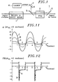
- the optical processing unit shown in the figure 1 has two main parts 1, 2 successively crossed by the optical signal modulated in intensity.
- the first part is a medium 1 to which the optical input signal is presented, and which produces a non-linear phase shift ⁇ NL depending on the intensity I s of the input signal.
- This medium 1 is transparent at the operating wavelength, that is to say that it causes practically no attenuation of the signal.
- the non-linear phase shift can be produced by the Kerr effect which results from a third order non-linearity.
- Kerr effect is not the only physical effect capable of producing the non-linear phase shift in medium 1.
- a phase shift of the same form (formula (1)) can in particular be obtained, more effectively , with a cascade of second order non-linearities in a material almost tuned in phase, such as lithium niobate (LiNbO 3 ) (see P.
- the second part of the processing unit is a phase-sensitive amplifier (PSA) 2, the input of which receives the phase-shifted signal delivered by the medium 1.
- a coupler 3 can consist in a dichroic blade as in the simple example shown diagrammatically in FIG. 1, superimposed on the phase shifted signal a pumping beam coming from a laser source 4.
- the pumping beam and the signal pass through a transparent non-linear medium where the energy transfer, and at the output of which another coupler 5 separates the pumping beam from the amplified signal.
- the gain G of a phase-sensitive parametric amplifier depends on the non-linearity of the medium used, the length z of interaction in this medium, the intensity I p of the pumping beam, and a relative phase ⁇ of the pumping beam with respect to the input signal of the amplifier which excites its two modes.
- the nonlinear medium is of type I, which is the case of crystals quasi-tuned in phase
- the two modes of the amplifier are of the same polarization.
- a type I medium degenerate into ⁇
- the two modes are also of the same pulsation ⁇ s , and the amplifier is always sensitive to the phase. This is the case of LiNbO 3 or KTP almost tuned in phase.
- the two modes have perpendicular polarization directions.
- Amplifier is phase sensitive when signal phase shifted supplied at its input is polarized at 45 ° with respect to to these two directions of polarization.
- the noise factor FB is not a significant parameter.
- the saturation of the gain is accompanied a reduction in the power of noise, such as shows figure 2, so that we can observe sub-fish intensity fluctuations in the signal output if the input signal of the unit comes from a source, such as a conventional laser, emitting light with a fish statistics.
- the unit then delivers the calm light, which can be observed by means of a spectrum analyzer.
- Figures 5 and 6 illustrate how one can switch from one operating region to another, i.e. select the type of processing performed by the unit, by adjusting the intensity range of the input signal .
- a control beam of wavelength ⁇ s and of programmable intensity, is superimposed on the signal to be processed by means of a coupler 17 at the input of the medium 1 producing the non-linear phase shift, and a beam of cancellation is possibly injected into the unit by the output of the amplifier sensitive to phase 2 by means of another coupler 18 to remove the control beam at the output.
- the signal-to-noise ratio is then preserved when the reflectivity of the coupler 18 is high (see M.
- the unit 1,2 operates as a modulation inverter when the control beam has the intensity I 1 , and as an amplifier when it has the intensity I 2 .
- phase shift ⁇ 0 shifts phase ⁇ to which amplifier 2 is sensitive (see relation (4)).
- the offset ⁇ 0 ⁇ p - ⁇ s is the difference between the phase ⁇ p of the pump and the phase ⁇ s of the signal at the input of the amplifier in the absence of non-linear phase shift (I s ⁇ 0 ), taken from an arbitrary common reference.
- the offset ⁇ 0 can therefore be adjusted by playing on the optical path (distances traveled and / or linear indices of the media crossed) either of the pumping beam or of the signal up to the input of the amplifier.
- phase ⁇ p of the pump can be adjusted simply using a mirror 6 (FIG. 1) mounted on a piezoelectric actuator 7 in the path followed by the pumping beam between its source 4 and the amplifier 2.
- the actuator 7 can be controlled by a servo circuit so that the desired processing is accomplished.
- Figures 7 and 8 show the differential gain g and the noise factor FB in small signal mode as a function of the phase ⁇ p of the pump in a given configuration ( ⁇ s fixed) when the intensity of the input signal ( plus the intensity of the small modulating signal) corresponds to a non-linear phase shift ⁇ NL of 0.5 radians.
- the noise factor is very close to 1 in amplification (Figure 8), especially for the highest differential gains.
- Figures 9 and 10 are graphs obtained under the same conditions as those of Figures 7 and 8, but for an intensity of the input signal giving rise to a non-linear phase shift ⁇ NL of 1 radian ( respectively 2 radians).
- ⁇ NL increases, the observed differential gains become larger, the observed differential gains in inversion get closer to those observed in simple amplification, and the noise factor is closer and closer to the ideal
- 1 in amplification but also in modulation inversion.
- phase adjusted is that ⁇ s of the phase shifted optical signal at the input of amplifier 2, which is equivalent, this adjustment can be carried out either upstream or downstream of the phase shifting medium 1, for example by means of one or more movable mirrors.
- the processing unit according to the invention does not involve light absorption, so you get very high bandwidth.
- the presence of the cavity then limits bandwidth. This limitation depends on the cavity quality. In such a case, the bandwidth generally will not exceed a few tens of MHz.
- the processing unit is carried out in progressive wave configuration, the value of this band mainly depends on the configuration and non-linear materials adopted. It is then located in the scale of a few hundred GHz.
- a unit according to the present invention can be hybrid or monolithic. It can be manufactured by serialization of two different materials (for example zinc selenide ZnSe for monitored non-linear phase shift of KTP for parametric amplification sensitive to phase) or, preferably, from a single material capable of producing the two non-linear effects. This is possible from organometallic materials, semiconductors, organic and glass.
- phase shift ⁇ 0 between the pump and the signal is then fixed, once and for all, "mechanically" when the device is produced, by checking the different lengths involved.
- a control system for this phase shift will allow the choice of output intensity and switching between the different operating modes.
- the phase can then be controlled by mechanical methods (mirrors mounted on piezoelectric wedges) or by optoelectronic methods.
- Silica fibers can be used to constitute the two parts of a unit according to the invention. Such optical fibers are commonly used for obtain a non-linear phase shift of the Kerr type, for example in the "Sagnac loops". The accumulated non-linear index over a length of 100 meters provides phase shifts of the order of ⁇ for relatively small signal strengths. Furthermore, these same fibers can present a second order nonlinearity when they are heat and / or electrically treated to obtain a near phase agreement (QPM) (see P.G. Kazansky et al: "High Second-Order Nonlinearities Induced in Lead Silicate Glass by Electron Beam Irradiation ", Optics Letters, Vol. 18, No. 9, May 1993, pages 693-695).
- QPM near phase agreement
- a possible realization represented on figure 13 consists in a fiber 8 of 100 meters including the last 10 centimeters are processed to obtain the non-linearity of the second order.
- a coupler allows to inject and extract the pumping beam in the non-linear medium of the second order.
- Figures 14 and 15 schematically show two monolithic crystals 9, 10 of a non-linear material such as LiNbO 3 can be the seat of the two effects put in series according to the invention.
- ⁇ k be the difference in wave vectors between the pump and the combination of waves carrying information.
- a non-linear waterfall effect, equivalent to the Kerr effect, on the other hand was demonstrated when a slight phase mismatch ( ⁇ k ⁇ 0) is carried out in the quasi-phase agreement (aforementioned article by P. Vidakovic et al.).
- the beam of pumping can be injected at the entrance of the guide or by a coupler installed in the second part of it.
- the length of the last section 15 is such that it allows parametric amplification when a pumping beam is injected using a coupler.
Landscapes
- Physics & Mathematics (AREA)
- Nonlinear Science (AREA)
- General Physics & Mathematics (AREA)
- Optics & Photonics (AREA)
- Electromagnetism (AREA)
- Engineering & Computer Science (AREA)
- Computer Networks & Wireless Communication (AREA)
- Signal Processing (AREA)
- Optical Modulation, Optical Deflection, Nonlinear Optics, Optical Demodulation, Optical Logic Elements (AREA)
Description
- des moyens déphaseurs agencés pour recevoir le signal optique d'entrée et lui appliquer un déphasage non-linéaire dépendant de son intensité ; et
- des moyens d'amplification optique paramétrique pour appliquer au signal optique déphasé produit par les moyens déphaseurs une amplification sensible à la phase par interaction avec un faisceau de pompage.
- on applique au signal optique d'entrée un déphasage non linéaire dépendant de son intensité ; et
- on amplifie le signal optique déphasé par interaction avec un faisceau de pompage dans un amplificateur optique paramétrique sensible à la phase.
- la figure 1 est un schéma de principe d'une unité de traitement optique selon l'invention ;
- la figure 2 est un graphique montrant les variations de l'intensité du signal (a) et du bruit (b) à la sortie en fonction de l'intensité du signal à l'entrée dans une unité selon l'invention ;
- les figures 3 et 4 sont des graphiques correspondant à celui de la figure 2 et montrant respectivement les variations du gain en régime de petits signaux et celles du facteur de bruit ;
- la figure 5 est un graphique intensité de sortie/intensité d'entrée illustrant une façon de sélectionner la fonction assurée au moyen d'un faisceau de contrôle ;
- la figure 6 est un schéma montrant des moyens de superposition et d'annulation du faisceau de contrôle ;
- les figures 7 à 12 sont des graphiques illustrant l'influence de la gamme d'intensité du signal d'entrée et de la phase du faisceau de pompage sur les fonctions assurées par une unité selon l'invention ; et
- les figures 13 à 15 sont des vues schématiques de matériaux non-linéaires employés dans des unités selon l'invention.
Claims (12)
- Unité de traitement d'un signal optique d'entrée modulé en intensité sans dégradation du rapport signal/bruit , comprenant, en série:des moyens déphaseurs (1) agencés pour recevoir le signal optique d'entrée et lui appliquer un déphasage non-linéaire (ΔΦNL) dépendant de son intensité (Is) ; etdes moyens d'amplification optique paramétrique (2) pour appliquer au signal optique déphasé produit par les moyens déphaseurs une amplification sensible à la phase par interaction avec un faisceau de pompage.
- Unité selon la revendication 1, dans laquelle les moyens déphaseurs (1) et les moyens d'amplification optique paramétrique (2) sont dans deux portions distinctes d'un même élément monolithique (8 ; 9; 10).
- Unité selon la revendication 2, dans laquelle ledit élément monolithique est une fibre optique (8).
- Unité selon la revendication 2, dans laquelle ledit élément monolithique est un cristal de matériau non-linéaire ayant au moins une région (11, 12 ; 14, 15) quasi-accordée en phase.
- Unité selon l'une quelconque des revendications 1 à 4, comprenant en outre des moyens de sélection de fonction par réglage de la gamme d'intensité du signal optique d'entrée.
- Unité selon la revendication 5, dans lequel lesdits moyens de sélection comprennent des moyens (17) pour superposer au signal optique d'entrée un faisceau de contrôle de même longueur d'onde et d'intensité programmable.
- Unité selon l'une quelconque des revendications 1 à 6, comprenant en outre des moyens (6, 7) de sélection de fonction par réglage d'un décalage de phase (Φ0) entre le faisceau de pompage et le signal déphasé à l'entrée des moyens d'amplification optique paramétrique (2).
- Unité selon la revendication 7, dans laquelle lesdits moyens de sélection par réglage du décalage de phase comprennent au moins un miroir mobile (6) sur lequel se réfléchit le faisceau de pompage le signal optique d'entrée ou le signal optique déphasé.
- Procédé d'amplification d'un signal optique d'entrée modulé en intensité sans dégradation du rapport signal/bruit, dans lequel :la gamme d'intensité (Is) du signal optique d'entrée et un décalage de phase (Φ0) entre le faisceau de pompage et le signal optique déphasé étant tels que le gain différentiel (g) entre le signal de sortie de l'amplificateur paramétrique et le signal optique d'entrée soit plus grand que 1.on applique au signal optique d'entrée un déphasage non-linéaire (ΔΦNL) dépendant de son intensité ; eton amplifie le signal optique déphasé par interaction avec un faisceau de pompage dans un amplificateur optique paramétrique sensible à la phase (2),
- Procédé d'inversion de la modulation d'un signal optique d'entrée modulé en intensité sans dégradation du rapport signal/bruit, dans lequel :la gamme d'intensité (Is) du signal optique d'entrée et un décalage de phase (Φ0) entre le faisceau de pompage et le signal optique déphasé étant tels que le gain différentiel (g) entre le signal de sortie de l'amplificateur paramétrique et le signal optique d'entrée soit négatif.on applique au signal optique d'entrée un déphasage non-linéaire (ΔΦNL) dépendant de son intensité ; eton amplifie le signal optique déphasé par interaction avec un faisceau de pompage dans un amplificateur optique paramétrique sensible à la phase (2),
- Procédé de production de lumière calme sans dégradation du rapport signal/bruit à partir d'un signal optique d'entrée issu d'une source laser dans lequel :la gamme d'intensité (Is) du signal optique d'entrée et un décalage de phase (Φ0) entre le faisceau de pompage et le signal optique déphasé étant tels que les fluctuations quantiques du signal de sortie de l'amplificateur paramétrique soient sub-poissonniennes.on applique au signal optique d'entrée un déphasage non-linéaire (ΔΦNL) dépendant de son intensité ; eton amplifie le signal optique déphasé par interaction avec un faisceau de pompage dans un amplificateur optique paramétrique sensible à la phase (2),
- Procédé selon la revendication 11, dans lequel ladite gamme d'intensité (Is) et ledit décalage de phase (Φ0) sont tels que le gain différentiel (g) entre le signal de sortie de l'amplificateur paramétrique et le signal optique d'entrée soit proche de 0.
Applications Claiming Priority (2)
| Application Number | Priority Date | Filing Date | Title |
|---|---|---|---|
| FR9701880 | 1997-02-18 | ||
| FR9701880A FR2759789B1 (fr) | 1997-02-18 | 1997-02-18 | Unite de traitement d'un signal optique module en intensite, procedes d'amplification, d'inversion de modulation et de production de lumiere calme pouvant etre mis en oeuvre avec une telle unite |
Publications (2)
| Publication Number | Publication Date |
|---|---|
| EP0859267A1 EP0859267A1 (fr) | 1998-08-19 |
| EP0859267B1 true EP0859267B1 (fr) | 2004-09-15 |
Family
ID=9503852
Family Applications (1)
| Application Number | Title | Priority Date | Filing Date |
|---|---|---|---|
| EP98400340A Expired - Lifetime EP0859267B1 (fr) | 1997-02-18 | 1998-02-13 | Dispositif optique pour l'amplification ou l'inversion de modulation à faible bruit ou la production de lumière calme |
Country Status (3)
| Country | Link |
|---|---|
| EP (1) | EP0859267B1 (fr) |
| DE (1) | DE69826159T2 (fr) |
| FR (1) | FR2759789B1 (fr) |
-
1997
- 1997-02-18 FR FR9701880A patent/FR2759789B1/fr not_active Expired - Fee Related
-
1998
- 1998-02-13 DE DE69826159T patent/DE69826159T2/de not_active Expired - Fee Related
- 1998-02-13 EP EP98400340A patent/EP0859267B1/fr not_active Expired - Lifetime
Also Published As
| Publication number | Publication date |
|---|---|
| DE69826159D1 (de) | 2004-10-21 |
| FR2759789B1 (fr) | 1999-04-30 |
| DE69826159T2 (de) | 2005-11-17 |
| EP0859267A1 (fr) | 1998-08-19 |
| FR2759789A1 (fr) | 1998-08-21 |
Similar Documents
| Publication | Publication Date | Title |
|---|---|---|
| CN103403616B (zh) | 光信号放大器 | |
| EP0718992B1 (fr) | Dispositif de régénération en ligne d'un signal tranmis par solitons via la modulation synchrone des solitons à l'aide d'un miroir optique non-linéaire | |
| CA2196333C (fr) | Modulateur kerr independant de la polarisation, et dispositif de recuperation toute optique d'horloge comprenant un tel modulateur | |
| WO2013045674A1 (fr) | Methode et dispositif de synchronisation de sources d'intrication pour reseau de communication quantique | |
| FR2742887A1 (fr) | Modulateur optique reglable d'amplitude et de phase, et regenerateur de solitons comprenant un tel modulateur | |
| EP0788017B1 (fr) | Miroir optique non linéaire en boucle (NOLM) indépendant de la polarisation | |
| Maji et al. | Numerical simulations of an all-optical parity generator and checker utilizing a reflective semiconductor optical amplifier at 200 Gbps | |
| Shehata et al. | Design and optimization of novel two inputs optical logic gates (NOT, AND, OR and NOR) based on single commercial TW-SOA operating at 40 Gbit/s | |
| Takanashi et al. | 4-dB quadrature squeezing with fiber-coupled PPLN ridge waveguide module | |
| Longhi et al. | Superluminal pulse propagation in linear and nonlinear photonic grating structures | |
| WO2014170331A1 (fr) | Generateur d'au moins trois faisceaux laser coherents dans le domaine de l'infrarouge et du visible | |
| EP0980538B1 (fr) | Dispositif et procede de regeneration pour train de solitons | |
| WO2013087645A1 (fr) | Procede et dispositif d'amplification parametrique optique d'impulsions a derive de frequence | |
| FR2725081A1 (fr) | Source optique compacte, basee sur le doublage de frequence d'un laser et auto-stabilisee par depeuplement de la pompe | |
| EP0859267A1 (fr) | Dispositif optique pour l'amplification ou l'inversion de modulation à faible bruit ou la production de lumière calme | |
| Michael et al. | Design of RSOA-based all-optical parity generator and checker | |
| Thomas et al. | Comparing teleportation to direct transmission in high-noise fibers carrying classical communications | |
| EP1089405A1 (fr) | Laser semiconducteur à générations paramétriques | |
| EP0908759A1 (fr) | Dispositif optique non-lineaire de traitement d'un signal optique, comprenant un interferometre à bras multiples | |
| EP4542795B1 (fr) | Source laser accordable bi-polarisation et bi-fréquence | |
| JP2014081578A (ja) | 光送信装置 | |
| JPH10260434A (ja) | 非線形光学媒質および非線形光学装置 | |
| WO2002019574A1 (fr) | Regenerateur tout-optique pour signaux multiplexes en longueur d'onde | |
| FR3111023A1 (fr) | Dispositif de génération de trains d'impulsions radiofréquences | |
| Shehata et al. | Cascaded Wavelength Converter Using Dual Pumping Power Based on Commercial SOA With Remarkable BER and Conversion Efficiency |
Legal Events
| Date | Code | Title | Description |
|---|---|---|---|
| PUAI | Public reference made under article 153(3) epc to a published international application that has entered the european phase |
Free format text: ORIGINAL CODE: 0009012 |
|
| AK | Designated contracting states |
Kind code of ref document: A1 Designated state(s): DE GB |
|
| AX | Request for extension of the european patent |
Free format text: AL;LT;LV;MK;RO;SI |
|
| 17P | Request for examination filed |
Effective date: 19990118 |
|
| AKX | Designation fees paid |
Free format text: DE GB |
|
| RBV | Designated contracting states (corrected) |
Designated state(s): DE GB |
|
| RAP1 | Party data changed (applicant data changed or rights of an application transferred) |
Owner name: ALCATEL |
|
| RAP1 | Party data changed (applicant data changed or rights of an application transferred) |
Owner name: AVANEX CORPORATION |
|
| GRAP | Despatch of communication of intention to grant a patent |
Free format text: ORIGINAL CODE: EPIDOSNIGR1 |
|
| GRAS | Grant fee paid |
Free format text: ORIGINAL CODE: EPIDOSNIGR3 |
|
| GRAA | (expected) grant |
Free format text: ORIGINAL CODE: 0009210 |
|
| AK | Designated contracting states |
Kind code of ref document: B1 Designated state(s): DE GB |
|
| PG25 | Lapsed in a contracting state [announced via postgrant information from national office to epo] |
Ref country code: GB Free format text: LAPSE BECAUSE OF FAILURE TO SUBMIT A TRANSLATION OF THE DESCRIPTION OR TO PAY THE FEE WITHIN THE PRESCRIBED TIME-LIMIT Effective date: 20040915 |
|
| REG | Reference to a national code |
Ref country code: GB Ref legal event code: FG4D Free format text: NOT ENGLISH |
|
| REF | Corresponds to: |
Ref document number: 69826159 Country of ref document: DE Date of ref document: 20041021 Kind code of ref document: P |
|
| GBV | Gb: ep patent (uk) treated as always having been void in accordance with gb section 77(7)/1977 [no translation filed] |
Effective date: 20040915 |
|
| PLBE | No opposition filed within time limit |
Free format text: ORIGINAL CODE: 0009261 |
|
| STAA | Information on the status of an ep patent application or granted ep patent |
Free format text: STATUS: NO OPPOSITION FILED WITHIN TIME LIMIT |
|
| PG25 | Lapsed in a contracting state [announced via postgrant information from national office to epo] |
Ref country code: DE Free format text: LAPSE BECAUSE OF NON-PAYMENT OF DUE FEES Effective date: 20050901 |
|
| 26N | No opposition filed |
Effective date: 20050616 |