EP0859248A2 - Multi-port optical device - Google Patents
Multi-port optical device Download PDFInfo
- Publication number
- EP0859248A2 EP0859248A2 EP98200436A EP98200436A EP0859248A2 EP 0859248 A2 EP0859248 A2 EP 0859248A2 EP 98200436 A EP98200436 A EP 98200436A EP 98200436 A EP98200436 A EP 98200436A EP 0859248 A2 EP0859248 A2 EP 0859248A2
- Authority
- EP
- European Patent Office
- Prior art keywords
- face
- grin lens
- optical
- optical device
- spaced
- Prior art date
- Legal status (The legal status is an assumption and is not a legal conclusion. Google has not performed a legal analysis and makes no representation as to the accuracy of the status listed.)
- Withdrawn
Links
Images


Classifications
-
- G—PHYSICS
- G02—OPTICS
- G02B—OPTICAL ELEMENTS, SYSTEMS OR APPARATUS
- G02B6/00—Light guides; Structural details of arrangements comprising light guides and other optical elements, e.g. couplings
- G02B6/24—Coupling light guides
- G02B6/26—Optical coupling means
- G02B6/28—Optical coupling means having data bus means, i.e. plural waveguides interconnected and providing an inherently bidirectional system by mixing and splitting signals
- G02B6/293—Optical coupling means having data bus means, i.e. plural waveguides interconnected and providing an inherently bidirectional system by mixing and splitting signals with wavelength selective means
- G02B6/29346—Optical coupling means having data bus means, i.e. plural waveguides interconnected and providing an inherently bidirectional system by mixing and splitting signals with wavelength selective means operating by wave or beam interference
- G02B6/29361—Interference filters, e.g. multilayer coatings, thin film filters, dichroic splitters or mirrors based on multilayers, WDM filters
- G02B6/2937—In line lens-filtering-lens devices, i.e. elements arranged along a line and mountable in a cylindrical package for compactness, e.g. 3- port device with GRIN lenses sandwiching a single filter operating at normal incidence in a tubular package
Definitions
- This invention relates generally to a optical device that uses a graded index lens to direct light towards a optical element; more particularly, in a preferred embodiment, the invention relates to a multi-port optical filtering device.
- optical filters are some of the most ubiquitous of all passive optical components found in most optical communication systems.
- One use of optical filters is in the field of optical communications where only a signal of a predetermined wavelength is to be passed.
- this invention is particularly useful with narrow band optical filters, it is not limited to filters which pass only a very narrow band of light (e.g. +0.2 nanometers or less) centered at a predetermined wavelength; however, since such filters are extremely difficult to make and consequently relatively expensive to manufacture the applicability of this invention for the narrow band is evident.
- One known means for providing a selective, narrow band, optical filter is by utilizing a wavelength selective interference filter element whose wavelength characteristic depends on the angle of incidence. Thus, by varying the angle of light incident upon the interference filter, the wavelength of the light that is passed by the filter varies.
- a filter element is described in United States Patent 5,331,651 issued July 19, 1994 and assigned to the Hewlett-Packard Company.
- Another filter of this type is described in allowed U.S. patent application 08/442,365 in the name of Si assigned to JDS Fitel Inc. of Canada.
- optical interference filters commonly comprise a pair of collimating graded index (GRIN) lenses having an interference coating or an interference filter sandwiched between the collimating end faces of the lenses.
- GRIN graded index
- Such a system requires two GRIN lenses and customarily, the use of a refractive index matching epoxy to glue input and output optical fibers to the lenses. Furthermore, index matching epoxy is used to glue the collimating end faces of the lenses to the optical filter.
- This structure in accordance with this invention obviates using an adhesive between a GRIN lens and optical fibers or optical elements, as this invention relies on having a gap between the lens ad adjacent optical elements such as a filter. Conveniently, the provision of this gap, creates space to dispose one or more other optical elements between the lens and for example the filter. In an embodiment not shown, an attenuating element can be placed between the lens and filter while not compromising efficient optical coupling of light.
- the gap provided between optical fibres and an adjacent GRIN lens also creates space for additional filters or elements to be inserted. This is highly advantageous where additional signal isolation may be required.
- an optical device comprising a GRIN lens having a first end face and a second end face, an input port disposed at a first location adjacent the first end face, an output port disposed at a second location adjacent the first end face, an at least partially reflective surface disposed at a third location adjacent the second end face of the GRIN lens, wherein the optical distance between the input port and the first end face of the GRIN lens is substantially the same as the optical distance from the second end face of the GRIN lens and the at least partially reflective surface.
- a GRIN lens 14 is disposed between input and output ports 10 and 12, and a reflective surface 16.
- the input port 10 and the output port 12 are both disposed a distance "d" on opposite side of an imaginary line (shown as a dotted line) that extends from the optical axis of the GRIN lens 14.
- the optical path length from the input port 10 to the input end face 14a of the GRIN lens 14 is the same as the optical path length from the output end face 14b of the GRIN lens 14 to the reflective surface 16.
- the GRIN lens is of a length (less than 0.25 pitch) that ensures that light launched into the input port 10 directed through the lens 14, is substantially collimated at the reflective surface 16 a distance from the end face of the lens. This ensures that light reflecting backwards along the path indicated by the dotted line will be substantially focused at the output port 12.
- the beam of light incident upon the surface 16 essentially remains in the same location and is confined to a small area relative to the size of the end face of the GRIN lens 14.
- the reflecting surface 16 is a wavelength selective interference filter whose wavelength characteristic depends on the angle of incidence; by varying the angle of light incident upon the interference filter, the wavelength of the light that is passed (or reflected) by the filter varies.
- a 3-port wavelength division multiplex (WDM) filter 28 is shown.
- Light of wavelengths ⁇ 1 to ⁇ 4 is launched into the input port 10 as a composite beam of light.
- the beam is incident upon the filter at an angle ⁇ 1 .
- light of wavelengths ⁇ 2 to ⁇ 4 are reflected and ⁇ 1 is passed.
- the transmission band is moved and light of wavelength ⁇ 2 is then passed.
- the filter is tunable.
- This tunability may be used in dynamic sense, by a means capable of moving the input and output ports simultaneously in a same direction toward or away from the optical axis.
- the filter may be tuned in a more static sense, during manufacturing, to achieve a particular response, after which the position of the ports can be fixed with an adhesive.
- Fig. 3 shows an alternative embodiment wherein a wide band filter 37 is placed in front of the reflective surface 16.
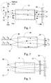
- a 3-port WDM system is shown wherein a pair of GRIN lenses 43a and 43b are provided having a narrow band WDM filter element 48 disposed between and separated from the lenses by an optical path length "s".
- the input and output ports are similarly spaced from their adjacent lens faces by the same optical path length "s".
- the lenses 43a and 43b are selected such that they collimate light at the filter element 48 launched into them at the input or output ports.
- Optical fiber 42, 44, and 46 provide input and output ports respectively.
- the narrow band WDM filter element 48 can be considerably smaller than the size of the end face of the GRIN lens. This is particularly advantageous since larger WDM filters such as the type that are often glued directly to and between a pair of GRIN lenses are more costly and difficult to manufacture due to their large size.
- a WDM filter is shown wherein two GRIN lenses are shown side-by-side.
- this arrangement is preferred to that shown in Figs. 2 or 4, as it facilitates easy placement of the input and output fibres without overcrowding.
- Fig. 5 provides an alternative arrangement.
- a six port filter is shown if Fig. 6, wherein two input ports IP1, IP2, and two output ports OP1 and OP2 are disposed adjacent a input end face GRIN lens 43a. Other output ports OP1 and OP2 are disposed adjacent the output face of the GRIN lens 43b. Although 6 ports are shown on this device, additional ports may be included provided there is sufficient space to place the input and output optical fibres (not shown) at the ports.
- Fig. 7 an embodiment is shown that is similar to the one shown if Fig. 2. However, in Fig. 7 the at least partially reflective surface 16 is tilted at a small angle. In accordance with this tilt, the input and output ports are located at different distances from the optical axis of the GRIN lens 16.
Abstract
Description
Claims (14)
- An optical device comprising:a GRIN lens having an first end face and a second end face;an input port disposed at a first location adjacent to and spaced from the first end face;an output port disposed at a second location, adjacent to and spaced from the first end face;an at least partially reflective surface disposed at a third location adjacent to and spaced from the second end face of the GRIN lens, wherein the optical distance between the input port and the first end face of the GRIN lens is substantially the same as the optical distance from the second end face of the GRIN lens and the at least partially reflective surface.
- An optical device as defined in claim 1, wherein the optical distance between the output port and the first end face of the GRIN lens is substantially the same as the optical distance from the second end face of the GRIN lens and the at least partially reflective surface.
- An optical device as defined in claim 1, wherein the GRIN lens has a length that will substantially collimate an incident beam launched into the input port at the at least partially reflecting surface.
- An optical device as defined in claim 3 wherein the at least partially reflecting surface is a completely reflecting mirror.
- An optical device as defined in claim 3 wherein the at least partially reflecting surface is a WDM interference filter having an output characteristic that varies with an angle of incident light.
- An optical device comprising:a GRIN lens having a first end face, a second end face, and an optical axis extending through its centre;an input and an output port, spaced on different sides of a path extending from the optical axis of the GRIN lens, the ports being spaced from and substantially equidistant from the first end face of the GRIN lens; and,an interference filter having an output characteristic that varies with an angle of incident light, said filter being spaced from the second end face of the GRIN lens and wherein light launched into the input port is collimated by the GRIN lens at the filter, and wherein the distance from the filter to the second end face of the GRIN lens is substantially the same as the distance from the first end face of the GRIN lens to one of the ports.
- An optical device as defined in claim 6, wherein the GRIN lens is less than a quarter pitch lens.
- An optical device comprising:a first GRIN lens having a first end face and a second end face;an input port disposed at a first location adjacent to and spaced from the first end face;an at least partially reflective surface disposed at a third location adjacent to and spaced from the second end face of the first GRIN lens, wherein the optical distance between the input port and the first end face of the first GRIN lens is substantially the same as the optical distance from the second end face of the first GRIN lens and the at least partially reflective surface; and,an output port disposed at a second location, adjacent to and spaced from the first input port for receiving light launched into the input port that has propagated through the first GRIN lens from the at last partially reflective surface.
- An optical device as defined in claim 8, further comprising a second GRIN lens disposed between the output port and the at least partially reflecting surface, to focus light received from the at least partially reflecting surface at the output input port.
- An optical device as defined in claim 9, further comprising a third GRIN lens disposed adjacent to and spaced from the at least partially reflecting surface for directing light that has transmitted through the at least partially reflecting element to a second output port.
- An optical device as defined in claim 10, wherein an optical distance from an end face of the second GRIN lens to the at least partially reflecting surface is approximately the same as the optical distance from an end face of the third GRIN lens to the at least partially reflecting surface.
- An optical device as defined in claim 11, wherein the optical distance from an end face of the second GRIN lens to the at least partially reflecting surface is approximately the same as the optical distance from an end face of the first GRIN lens to the at least partially reflecting surface.
- An optical device as defined in claim 8, wherein the first GRIN lens is of a length that is of a length that is other than a quarter pitch or multiple thereof.
- An optical device as defined in claim 1, wherein the first GRIN lens is of a length that is of a length that is other than a quarter pitch or multiple thereof.
Applications Claiming Priority (2)
| Application Number | Priority Date | Filing Date | Title |
|---|---|---|---|
| US800061 | 1985-11-20 | ||
| US08/800,061 US5799121A (en) | 1997-02-14 | 1997-02-14 | Multi-port optical device |
Publications (2)
| Publication Number | Publication Date |
|---|---|
| EP0859248A2 true EP0859248A2 (en) | 1998-08-19 |
| EP0859248A3 EP0859248A3 (en) | 1999-09-01 |
Family
ID=25177412
Family Applications (1)
| Application Number | Title | Priority Date | Filing Date |
|---|---|---|---|
| EP98200436A Withdrawn EP0859248A3 (en) | 1997-02-14 | 1998-02-12 | Multi-port optical device |
Country Status (4)
| Country | Link |
|---|---|
| US (1) | US5799121A (en) |
| EP (1) | EP0859248A3 (en) |
| JP (1) | JPH1123999A (en) |
| CA (1) | CA2223661A1 (en) |
Cited By (1)
| Publication number | Priority date | Publication date | Assignee | Title |
|---|---|---|---|---|
| EP1085353A2 (en) * | 1999-07-22 | 2001-03-21 | JDS Uniphase Inc. | Lens arrangement for enhancing the coupling of light shifted by an optical element |
Families Citing this family (39)
| Publication number | Priority date | Publication date | Assignee | Title |
|---|---|---|---|---|
| US6130984A (en) * | 1997-05-19 | 2000-10-10 | E-Tek Dynamics, Inc. | Miniature variable optical attenuator |
| US6084994A (en) * | 1998-04-02 | 2000-07-04 | Oplink Communications, Inc. | Tunable, low back-reflection wavelength division multiplexer |
| US6137930A (en) | 1998-07-08 | 2000-10-24 | Optical Switch Corporation | Method and apparatus for aligning optical fibers |
| US6236787B1 (en) | 1998-07-08 | 2001-05-22 | Optical Switch Corporation | Method and apparatus for aligning optical fibers using an alignment spacer |
| US6253007B1 (en) * | 1998-07-08 | 2001-06-26 | Optical Switch Corporation | Method and apparatus for connecting optical fibers |
| US6498676B1 (en) * | 1998-08-07 | 2002-12-24 | Jds Fitel Inc. | Optical filter for use or with an optical amplifier |
| US6459844B1 (en) | 1998-10-30 | 2002-10-01 | Jds Uniphase Corporation | Tunable fiber optic filter |
| US6393191B1 (en) | 1999-04-01 | 2002-05-21 | Jds Uniphase Corporation | Optical terminal for optical fibers with output angle control |
| US6454465B1 (en) | 2000-03-31 | 2002-09-24 | Corning Incorporated | Method of making an optical fiber collimating device |
| US6608685B2 (en) | 2000-05-15 | 2003-08-19 | Ilx Lightwave Corporation | Tunable Fabry-Perot interferometer, and associated methods |
| US6729770B2 (en) * | 2000-06-22 | 2004-05-04 | Avanex Corporation | Methods of making a multiple-port optical package |
| US6343166B1 (en) | 2000-06-22 | 2002-01-29 | Corning Incorporated | Three-port filter and method of manufacture |
| US6960026B2 (en) | 2000-06-22 | 2005-11-01 | Avanex Corporation | Precision fiber ferrules |
| US6767139B2 (en) | 2000-06-22 | 2004-07-27 | Avanex Corporation | Six-port optical package and method of manufacturing |
| US6764224B2 (en) | 2000-06-22 | 2004-07-20 | Avanex Corporation | Precision fiber ferrules |
| US6760516B2 (en) | 2000-06-22 | 2004-07-06 | Avanex Corporation | Multiple -port optical package and DWDM module |
| US6404958B1 (en) | 2000-10-31 | 2002-06-11 | Digital Optics Corp. | Intergrated optical coupler |
| DE10101264A1 (en) * | 2001-01-12 | 2002-07-25 | Aifotec Ag Fiberoptics | Optical coupling device for waveguides such as glass fibers, uses GRIN lenses with input and output ports formed by waveguide ends |
| JP2002243991A (en) * | 2001-02-15 | 2002-08-28 | Nippon Sheet Glass Co Ltd | Coupled optical system and optical device using the same |
| US6721468B2 (en) | 2001-06-08 | 2004-04-13 | Ilx Lightwave Corporation | Resonantly driven fiber polarization scrambler |
| US6885782B2 (en) * | 2001-06-26 | 2005-04-26 | Ilx Lightwave Corporation | Feedback polarization controller |
| US6782146B2 (en) | 2001-09-28 | 2004-08-24 | Corning Incorporated | Multiple polarization combiner-splitter-isolator and method of manufacturing the same |
| US6999663B2 (en) * | 2001-10-31 | 2006-02-14 | Adc Telecommunications, Inc. | Fiber optic tap |
| US6860644B2 (en) | 2001-10-31 | 2005-03-01 | Adc Telecommunications, Inc. | Dual fiber collimator assembly pointing control |
| US6804435B2 (en) * | 2002-03-21 | 2004-10-12 | Adc Telecommunications, Inc. | Fiber collimator coupling assembly |
| US6961496B2 (en) * | 2002-03-26 | 2005-11-01 | Avanex Corporation | Optical package with cascaded filtering |
| US6950574B2 (en) * | 2002-07-29 | 2005-09-27 | Adc Telecommunications, Inc. | Angle tuning wavelength sensitive filters using a variable focal length lens |
| US6925227B2 (en) * | 2002-08-30 | 2005-08-02 | Fujikura Ltd. | Optical device |
| US20040156596A1 (en) * | 2002-09-06 | 2004-08-12 | Adc Telecommunications, Inc. | Fiber optic tap with compensated spectral filter |
| US20040161220A1 (en) * | 2002-09-09 | 2004-08-19 | Adc Telecommunications, Inc. | Method for face-mounting optical components and devices using same |
| JP2004133038A (en) * | 2002-10-08 | 2004-04-30 | Nippon Sheet Glass Co Ltd | Filter module |
| US6915031B2 (en) * | 2002-10-22 | 2005-07-05 | Finisar Corporation | Switch using electrooptic polarization splitter and combiner |
| US6894846B1 (en) | 2003-10-30 | 2005-05-17 | Alliance Fiber Optic Products | Optical add/drop apparatus and the method for making the same |
| US7356222B2 (en) | 2003-11-06 | 2008-04-08 | Nippon Sheet Glass Co., Ltd. | Wavelength selective optical device and method of tuning a wavelength characteristic of the same |
| US6999656B1 (en) | 2004-03-04 | 2006-02-14 | Alliance Fiber Optic Products, Inc. | Optical device with concave mirror |
| CN101076749B (en) * | 2004-11-15 | 2011-05-04 | 日立化成工业株式会社 | Optical reflector, optical system and optical multiplexer/demultiplexer device |
| US7403681B2 (en) | 2006-03-08 | 2008-07-22 | Nippon Sheet Glass Company, Ltd. | Wavelength selective optical device and method of tuning wavelength characteristics |
| DE102007004514A1 (en) * | 2007-01-24 | 2008-07-31 | Schleifring Und Apparatebau Gmbh | Two-channel multimode rotary transmitter |
| US7616851B1 (en) * | 2008-06-26 | 2009-11-10 | Lockheed Martin Corporation | Tunable wavelength filter device |
Citations (8)
| Publication number | Priority date | Publication date | Assignee | Title |
|---|---|---|---|---|
| EP0360686A2 (en) * | 1988-09-20 | 1990-03-28 | Nippon Telegraph And Telephone Corporation | All-optical switch apparatus using a nonlinear etalon |
| EP0463779A1 (en) * | 1990-06-16 | 1992-01-02 | Gec-Marconi Avionics (Holdings) Limited | Fibre optic waveguide beam splitter |
| JPH06175069A (en) * | 1992-12-08 | 1994-06-24 | Matsushita Electric Ind Co Ltd | Optical isolator |
| WO1995016216A1 (en) * | 1993-12-10 | 1995-06-15 | Jds Fitel Inc. | Optical non-reciprocal devices |
| US5555330A (en) * | 1994-12-21 | 1996-09-10 | E-Tek Dynamics, Inc. | Wavelength division multiplexed coupler with low crosstalk between channels and integrated coupler/isolator device |
| CA2146738A1 (en) * | 1995-04-10 | 1996-10-11 | Y. Calvin Si | Narrow Band Filter and Method of Making Same |
| CA2147703A1 (en) * | 1995-04-24 | 1996-10-25 | Gary Stephen Duck | Multi-port fiber optical device |
| US5680237A (en) * | 1995-11-16 | 1997-10-21 | Jds Fitel Inc. | Graded index lens system and method for coupling light |
Family Cites Families (4)
| Publication number | Priority date | Publication date | Assignee | Title |
|---|---|---|---|---|
| US4474424A (en) * | 1981-03-20 | 1984-10-02 | At&T Bell Laboratories | Optical multi/demultiplexer using interference filters |
| US4550975A (en) * | 1982-04-29 | 1985-11-05 | At&T Bell Laboratories | Optical coupling devices |
| DE3217984A1 (en) * | 1982-05-13 | 1983-11-17 | Philips Kommunikations Industrie AG, 8500 Nürnberg | GRADIENT STICK LENS WITH LIGHTWAVE GUIDES |
| US4486071A (en) * | 1982-07-07 | 1984-12-04 | At&T Bell Laboratories | Optical coupling device |
-
1997
- 1997-02-14 US US08/800,061 patent/US5799121A/en not_active Expired - Lifetime
- 1997-12-04 CA CA002223661A patent/CA2223661A1/en not_active Abandoned
-
1998
- 1998-02-12 EP EP98200436A patent/EP0859248A3/en not_active Withdrawn
- 1998-02-13 JP JP10048867A patent/JPH1123999A/en active Pending
Patent Citations (8)
| Publication number | Priority date | Publication date | Assignee | Title |
|---|---|---|---|---|
| EP0360686A2 (en) * | 1988-09-20 | 1990-03-28 | Nippon Telegraph And Telephone Corporation | All-optical switch apparatus using a nonlinear etalon |
| EP0463779A1 (en) * | 1990-06-16 | 1992-01-02 | Gec-Marconi Avionics (Holdings) Limited | Fibre optic waveguide beam splitter |
| JPH06175069A (en) * | 1992-12-08 | 1994-06-24 | Matsushita Electric Ind Co Ltd | Optical isolator |
| WO1995016216A1 (en) * | 1993-12-10 | 1995-06-15 | Jds Fitel Inc. | Optical non-reciprocal devices |
| US5555330A (en) * | 1994-12-21 | 1996-09-10 | E-Tek Dynamics, Inc. | Wavelength division multiplexed coupler with low crosstalk between channels and integrated coupler/isolator device |
| CA2146738A1 (en) * | 1995-04-10 | 1996-10-11 | Y. Calvin Si | Narrow Band Filter and Method of Making Same |
| CA2147703A1 (en) * | 1995-04-24 | 1996-10-25 | Gary Stephen Duck | Multi-port fiber optical device |
| US5680237A (en) * | 1995-11-16 | 1997-10-21 | Jds Fitel Inc. | Graded index lens system and method for coupling light |
Non-Patent Citations (1)
| Title |
|---|
| PATENT ABSTRACTS OF JAPAN vol. 018, no. 510 (P-1804), 26 September 1994 (1994-09-26) -& JP 06 175069 A (MATSUSHITA ELECTRIC IND CO LTD), 24 June 1994 (1994-06-24) * |
Cited By (2)
| Publication number | Priority date | Publication date | Assignee | Title |
|---|---|---|---|---|
| EP1085353A2 (en) * | 1999-07-22 | 2001-03-21 | JDS Uniphase Inc. | Lens arrangement for enhancing the coupling of light shifted by an optical element |
| EP1085353A3 (en) * | 1999-07-22 | 2003-07-30 | JDS Uniphase Inc. | Lens arrangement for enhancing the coupling of light shifted by an optical element |
Also Published As
| Publication number | Publication date |
|---|---|
| EP0859248A3 (en) | 1999-09-01 |
| JPH1123999A (en) | 1999-01-29 |
| US5799121A (en) | 1998-08-25 |
| CA2223661A1 (en) | 1998-08-14 |
Similar Documents
| Publication | Publication Date | Title |
|---|---|---|
| US5799121A (en) | Multi-port optical device | |
| CA2223667C (en) | Grin lensed optical device | |
| US6498876B1 (en) | Multi-port fiber optic device with v-groove ferrule | |
| US5612824A (en) | Narrow band filter and method of making same | |
| CA2029171C (en) | Multiport optical devices | |
| US5796889A (en) | Integrated WDM coupler devices for fiberoptic networks | |
| US5629995A (en) | Wavelength filter arrangements for use in fiber optics | |
| US6198864B1 (en) | Optical wavelength demultiplexer | |
| US6281977B1 (en) | Interferometric optical device including an optical resonator | |
| US4958897A (en) | Thin film optical component for use in optical transmission lines and method of manufacturing the same | |
| US5850493A (en) | Device for focusing light through an optical component | |
| CA2245054C (en) | Multi-pass optical filter | |
| US5754718A (en) | Hybrid optical filtering circuit | |
| US5946435A (en) | Method and system for providing an improved three port wavelength division multiplexer | |
| US6400862B1 (en) | Retro-reflective multi-port filter device with triple-fiber ferrule | |
| US6122420A (en) | Optical loopback apparatus | |
| JPS6145801B2 (en) | ||
| US6941072B2 (en) | Compact optical multiplexer/demultiplexer | |
| US5680237A (en) | Graded index lens system and method for coupling light | |
| US6535668B2 (en) | Retro-reflective multi-port filter device with triple-fiber ferrule | |
| US6292604B1 (en) | Optical coupler arrangement | |
| JP2000131542A (en) | Optical transmission and reception module | |
| US6577398B1 (en) | Resonant optical cavity | |
| JPH07333462A (en) | Parts for optical communication | |
| CA2229956C (en) | Optical filter multiplexing/demultiplexing device |
Legal Events
| Date | Code | Title | Description |
|---|---|---|---|
| PUAI | Public reference made under article 153(3) epc to a published international application that has entered the european phase |
Free format text: ORIGINAL CODE: 0009012 |
|
| AK | Designated contracting states |
Kind code of ref document: A2 Designated state(s): DE FR GB IE |
|
| AX | Request for extension of the european patent |
Free format text: AL;LT;LV;MK;RO;SI |
|
| PUAL | Search report despatched |
Free format text: ORIGINAL CODE: 0009013 |
|
| AK | Designated contracting states |
Kind code of ref document: A3 Designated state(s): AT BE CH DE DK ES FI FR GB GR IE IT LI LU MC NL PT SE |
|
| AX | Request for extension of the european patent |
Free format text: AL;LT;LV;MK;RO;SI |
|
| 17P | Request for examination filed |
Effective date: 20000212 |
|
| AKX | Designation fees paid |
Free format text: DE FR GB IE |
|
| STAA | Information on the status of an ep patent application or granted ep patent |
Free format text: STATUS: THE APPLICATION IS DEEMED TO BE WITHDRAWN |
|
| 18D | Application deemed to be withdrawn |
Effective date: 20030701 |