EP0858846B1 - Apparatus for cold bending of metal sheets for making elongated articles with predetermined profile - Google Patents
Apparatus for cold bending of metal sheets for making elongated articles with predetermined profile Download PDFInfo
- Publication number
- EP0858846B1 EP0858846B1 EP98830068A EP98830068A EP0858846B1 EP 0858846 B1 EP0858846 B1 EP 0858846B1 EP 98830068 A EP98830068 A EP 98830068A EP 98830068 A EP98830068 A EP 98830068A EP 0858846 B1 EP0858846 B1 EP 0858846B1
- Authority
- EP
- European Patent Office
- Prior art keywords
- sheet
- plates
- stop
- bending
- spindles
- Prior art date
- Legal status (The legal status is an assumption and is not a legal conclusion. Google has not performed a legal analysis and makes no representation as to the accuracy of the status listed.)
- Expired - Lifetime
Links
- 238000005452 bending Methods 0.000 title claims description 25
- 239000002184 metal Substances 0.000 title claims description 16
- 230000010355 oscillation Effects 0.000 claims description 4
- 230000000284 resting effect Effects 0.000 claims description 4
- 230000001360 synchronised effect Effects 0.000 claims 1
- 238000004519 manufacturing process Methods 0.000 description 2
- 241000490025 Schefflera digitata Species 0.000 description 1
- 230000001419 dependent effect Effects 0.000 description 1
- 238000000605 extraction Methods 0.000 description 1
- 235000015250 liver sausages Nutrition 0.000 description 1
- 238000006467 substitution reaction Methods 0.000 description 1
Images




Classifications
-
- B—PERFORMING OPERATIONS; TRANSPORTING
- B21—MECHANICAL METAL-WORKING WITHOUT ESSENTIALLY REMOVING MATERIAL; PUNCHING METAL
- B21D—WORKING OR PROCESSING OF SHEET METAL OR METAL TUBES, RODS OR PROFILES WITHOUT ESSENTIALLY REMOVING MATERIAL; PUNCHING METAL
- B21D5/00—Bending sheet metal along straight lines, e.g. to form simple curves
- B21D5/01—Bending sheet metal along straight lines, e.g. to form simple curves between rams and anvils or abutments
- B21D5/015—Bending sheet metal along straight lines, e.g. to form simple curves between rams and anvils or abutments for making tubes
Definitions
- the present invention relates to production of elongated articles with predetermined section profile. It is known the need to produce elongated articles with predetermined profile from sheets of metal.
- Elongated articles of this kind are usually used e.g. for covering some particulars of furniture or the like.
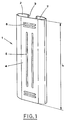
- Figure 1 shows an example of an article of the above mentioned type, indicated with 1.
- This article 1 is substantially formed of a sheet of metal, of length L, whose longitudinal edges 2 are folded so as to form "C" with the edges 3 turned inward.
- the front surface 4 of the article 1 has longitudinal ribs 5 and transversal ribs 6, obtained by deep drawing of the sheet of metal.
- the elongated articles of the type illustrated in Figure 1 are produced from a continuous section obtained from a sheet of metal.
- This section is cut according to the length of the articles to be produced.
- the above mentioned apparatuses generally do not allow to produce special relieves, such as the above mentioned ribs or the like.
- the machine includes basically a base plate, means for locking the metal sheet being folded in a position on the base plate, and folding lateral cross-pieces, situated on both sides of the base plate.
- Each of the folding lateral cross-pieces is hinged to the base plate, along a corresponding edge thereof. Furthermore, each of the folding lateral cross-pieces is composed of two cross-bars hinged to each other. By operating in succession, one after the other, the cross-bars, the metal sheet can be bent and a series of parallel folds are made along the longitudinal extension of the metal sheet to shape it into a polygonal profiled bar.
- the cross-bars include longitudinally extending pads which are aimed at forming a pre-selected thickness. These pads can be removed and replaced with other ones of different thickness.
- the hinge axes can be adjusted in their position to allow different folding of the metal sheets, but they are stationary during operation. The locking action is performed by the means, which include a pressing plate, by means of suitable pads also removable to be replaced with others of different thickness.
- the object of the present invention is to provide an apparatus which allows to obtain elongated articles with predetermined section profile by only one operation in which a metal sheet is cold bent.
- Another object of the present invention is to obtain these elongated articles by an apparatus of limited dimension.
- Still further object of the invention is to provide a bending apparatus, whose characteristic is versatility, which allows to rapidly and easily change the elongated articles being produced.
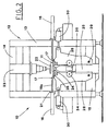
- the numeral 10 indicates the apparatus for cold bending of metal sheets 11 for obtaining elongated articles 1 with predetermined section profile.
- the apparatus 10 includes a structure 12 equipped with uprights 13 connected by an upper cross-bar 14 and a lower cross-bar 15.
- the uprights 13 carry respective actuators 16, opposite to each other and aligned along a horizontal axis.
- the stems 16a of these actuators 16 carry at their extremities relative elements 17 for supporting the opposite sides of the metal sheet 11 being bent, resting thereon.
- These supporting elements 17 are substantially formed by squared and parallel angle bars, which are arranged horizontal and coplanar.
- the angle bars are provided, at one extremity, with suitable shoulders 18 acting as stops for the sheet 11.
- Each of these angle bars is fastened to a pair of rods 19 which slide through relative sleeves 20 carried by a bar 21, which is integral with the uprights 13 of the frame 12 ( Figure 5).
- a form 22 having a section according to the predetermined profile of the articles to produce, is carried parallel and in median position with respect to the supporting angle bars 17, over the sheet 11 resting on the supporting angle bars 17.
- the form 22 is operated vertically, perpendicularly with respect to its longitudinal axis, by a related actuator 23 carried by an upper cross-bar 14 of the frame.
- the form 22 is removably fastened to the stem 23a of this actuator 23, so that it can be changed.
- the form 22 is aimed at clamping the sheet 11 being formed, resting on the supporting angle bars 17, to an opposite stops 24 formed by an elongated horizontal plate, parallel and located in a median position with respect to the angle bars 17.
- the stop plate 24 is operated vertically by a related actuator 25 carried by a lower cross-bar 15 of the frame. Also the stop plate 24 is removably fastened to the stem 25a of the actuator 25 so that it can be replaced.
- the apparatus further includes a couple of plates 28 pivoted so that they can oscillate on a vertical plan transversal to the form 22.
- the plates 28 are pivoted on pins 29 fixed to the lower cross-bar 15 of the frame, and are operated synchronously, in opposite directions, by relative actuators 30 carried by the uprights 13.
- Two spindles 27 are fitted to the plates 28 and are arranged paralle to the stop plate 24 at either side thereof. Respective bending members 26 are set to rotate around the spindles 27 and are parallel to the form 22.
- the bending members 26 are arranged at either side of the stop plate 24.
- the bending members 26 are formed by elongated plates, suitably shaped, are driven into rotation by respective rack 31 engaged with relative pinions 32 integral with the spindles 27 ( Figure 3a).
- the racks 31 are operated by further actuators 33, that are carried respectively by the pates 28.
- the plates 28 carry also respective rollers 34 that are brought to strike against opposite sides of a central shoulder 35 acting as a stop.
- the apparatus includes also an extractor 36 acting along a direction longitudinal with respect to the form 22 so as to take out the already formed article 1 therefrom ( Figure 5).
- the form 22 operated vertically by its actuator 23, clamps the sheet 11 to the stop plate 24 ( Figure 3b).
- the angle bars 17 are brought to a retracted position, in which they do not interfere with subsequent bending operations performed on the sheet 11.
- the bending members 26 are provided with respective teeth 26a, arranged along their edges.
- the task of the teeth is that of introducing the longitudinal edges of the sheet 11 inside the grooves 22a made longitudinally in the form 22, so as to turn inwards the edges 3 of the elongated article 1.
- the so obtained article 1 is then extracted from the form 22 by operating the extractor 36, as indicated with the broken line 36a in Figure 5.
- the size and shape of the form 22 are determined taking in consideration the spring back of the metallic sheet which occurs, when the bending operation is completed. This spring back is advantageous because it facilitates extraction of the already formed article 1 from the form 22.
- the apparatus fulfils the object of producing elongated articles with predetermined section profile by only one cold bending operation performed on the sheet which is already shaped in relation to the size of the articles to be obtained.
- this operation allows to produce special relieves, such as the above mentioned ribs or the like. These relieves can have even complicated shapes.
- One characteristic of the bending apparatus is that it allows to rapidly and easily change the kind of elongated articles being produced.
- the apparatus is very small. In fact, its size corresponds to the length of the articles to be obtained.
Landscapes
- Engineering & Computer Science (AREA)
- Mechanical Engineering (AREA)
- Bending Of Plates, Rods, And Pipes (AREA)
- Shaping By String And By Release Of Stress In Plastics And The Like (AREA)
Description
- The present invention relates to production of elongated articles with predetermined section profile. It is known the need to produce elongated articles with predetermined profile from sheets of metal.
- Elongated articles of this kind are usually used e.g. for covering some particulars of furniture or the like.
- Figure 1 shows an example of an article of the above mentioned type, indicated with 1.
- This
article 1 is substantially formed of a sheet of metal, of length L, whoselongitudinal edges 2 are folded so as to form "C" with theedges 3 turned inward. - The
front surface 4 of thearticle 1 haslongitudinal ribs 5 andtransversal ribs 6, obtained by deep drawing of the sheet of metal. - At present, the elongated articles of the type illustrated in Figure 1 are produced from a continuous section obtained from a sheet of metal.
- This section is cut according to the length of the articles to be produced.
- This requires big, in particular very long apparatuses for folding the sheet of metal until the predetermined profile is obtained.
- The above mentioned apparatuses generally do not allow to produce special relieves, such as the above mentioned ribs or the like.
- Therefore, these relieves must be done separately, by a special deep drawing operation.
- Moreover, these apparatuses are little flexible, and consequently, the change of production requires the substitution of many elements and causes long breaks in the machine operation which results in productivity reduction.
- From the FR-B-1.052.140 a machine is known for cold-bending metal sheets, in particular for producing polygonal profiled bars. The machine includes basically a base plate, means for locking the metal sheet being folded in a position on the base plate, and folding lateral cross-pieces, situated on both sides of the base plate.
- Each of the folding lateral cross-pieces is hinged to the base plate, along a corresponding edge thereof. Furthermore, each of the folding lateral cross-pieces is composed of two cross-bars hinged to each other. By operating in succession, one after the other, the cross-bars, the metal sheet can be bent and a series of parallel folds are made along the longitudinal extension of the metal sheet to shape it into a polygonal profiled bar. The cross-bars include longitudinally extending pads which are aimed at forming a pre-selected thickness. These pads can be removed and replaced with other ones of different thickness. The hinge axes can be adjusted in their position to allow different folding of the metal sheets, but they are stationary during operation. The locking action is performed by the means, which include a pressing plate, by means of suitable pads also removable to be replaced with others of different thickness.
- The object of the present invention is to provide an apparatus which allows to obtain elongated articles with predetermined section profile by only one operation in which a metal sheet is cold bent.
- Another object of the present invention is to obtain these elongated articles by an apparatus of limited dimension.
- Still further object of the invention is to provide a bending apparatus, whose characteristic is versatility, which allows to rapidly and easily change the elongated articles being produced.
- The above mentioned objects are obtained by an apparatus in accordance with
claim 1. The dependent claims describe further embodiments of the invention. - The characteristics of the invention are pointed out in the following description, with particular reference to the enclosed drawings, in which:
- Figure 1 is a perspective view of an elongated article produced by the apparatus being the subject of the invention;
- Figure 2 is a schematic lateral view of the subject apparatus;
- Figures 3a and 3b show an enlarged part of the above lateral view of the apparatus, in different working steps;
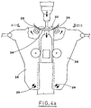
- Figures 4a, 4b and 4c show the same lateral partial view of the apparatus in other working steps;
- Figure 5 is a corresponding partial plan schematic view of the apparatus.
- With reference to the above mentioned figures, the
numeral 10 indicates the apparatus for cold bending ofmetal sheets 11 for obtainingelongated articles 1 with predetermined section profile. - The
apparatus 10 includes astructure 12 equipped withuprights 13 connected by anupper cross-bar 14 and alower cross-bar 15. - In their central part, the
uprights 13 carryrespective actuators 16, opposite to each other and aligned along a horizontal axis. - The
stems 16a of theseactuators 16 carry at their extremitiesrelative elements 17 for supporting the opposite sides of themetal sheet 11 being bent, resting thereon. - These supporting
elements 17 are substantially formed by squared and parallel angle bars, which are arranged horizontal and coplanar. The angle bars are provided, at one extremity, withsuitable shoulders 18 acting as stops for thesheet 11. - Each of these angle bars is fastened to a pair of
rods 19 which slide throughrelative sleeves 20 carried by abar 21, which is integral with theuprights 13 of the frame 12 (Figure 5). - A
form 22 having a section according to the predetermined profile of the articles to produce, is carried parallel and in median position with respect to the supportingangle bars 17, over thesheet 11 resting on the supportingangle bars 17. - The
form 22 is operated vertically, perpendicularly with respect to its longitudinal axis, by arelated actuator 23 carried by anupper cross-bar 14 of the frame. - The
form 22 is removably fastened to thestem 23a of thisactuator 23, so that it can be changed. Theform 22 is aimed at clamping thesheet 11 being formed, resting on the supportingangle bars 17, to anopposite stops 24 formed by an elongated horizontal plate, parallel and located in a median position with respect to theangle bars 17. - The
stop plate 24 is operated vertically by arelated actuator 25 carried by alower cross-bar 15 of the frame. Also thestop plate 24 is removably fastened to thestem 25a of theactuator 25 so that it can be replaced. - The apparatus further includes a couple of
plates 28 pivoted so that they can oscillate on a vertical plan transversal to theform 22. In their lower part, theplates 28 are pivoted onpins 29 fixed to thelower cross-bar 15 of the frame, and are operated synchronously, in opposite directions, byrelative actuators 30 carried by theuprights 13. - Two
spindles 27 are fitted to theplates 28 and are arranged paralle to thestop plate 24 at either side thereof.Respective bending members 26 are set to rotate around thespindles 27 and are parallel to theform 22. - Also the
bending members 26 are arranged at either side of thestop plate 24. - The
bending members 26 are formed by elongated plates, suitably shaped, are driven into rotation byrespective rack 31 engaged withrelative pinions 32 integral with the spindles 27 (Figure 3a). Theracks 31 are operated byfurther actuators 33, that are carried respectively by thepates 28. - The
plates 28 carry alsorespective rollers 34 that are brought to strike against opposite sides of acentral shoulder 35 acting as a stop. - The apparatus includes also an
extractor 36 acting along a direction longitudinal with respect to theform 22 so as to take out the already formedarticle 1 therefrom (Figure 5). - Operation of the apparatus will be described beginning from the step in which a
sheet 11 to be formed is put on theangle bars 17, as shown in Figure 3a. - The
form 22, operated vertically by itsactuator 23, clamps thesheet 11 to the stop plate 24 (Figure 3b). - The
angle bars 17 are brought to a retracted position, in which they do not interfere with subsequent bending operations performed on thesheet 11. - At this point, the
bending plates 26, operated by therespective racks 31, are rotated in suitable time relation with oscillation of theplates 28. Meanwhile, theform 22 and of thestop plate 24 are operated by therespective actuators 23 and 25 (Figure 4a). - The bending action of the
bending members 26 together with the above mentioned movement of theform 22 make the two edges of thesheet 11 fold around the form 22 (Figure 4b). - It is to be pointed out that the above mentioned combined rotation movements of the
bending members 26, oscillation movements of theplates 28 and translation movements of theform 22, allow to further fold thesheet 11 around theform 22 without sliding. This is obtained because thebending members 26 "rotate" on the surface of thesheet 11. - In practice, these movements are suitably programmed in relation to the profile to be obtained.
- When this folding step is finished, the
sheet 11 is completely folded around theform 22 and assumes its shape (Figure 4c). - It is to be pointed out that, in the illustrated case, the
bending members 26 are provided withrespective teeth 26a, arranged along their edges. The task of the teeth is that of introducing the longitudinal edges of thesheet 11 inside thegrooves 22a made longitudinally in theform 22, so as to turn inwards theedges 3 of theelongated article 1. - Otherwise, these turned
inward edges 3 can be made directly on thesheet 11 to be formed. - The so obtained
article 1 is then extracted from theform 22 by operating theextractor 36, as indicated with thebroken line 36a in Figure 5. - Obviously, the size and shape of the
form 22 are determined taking in consideration the spring back of the metallic sheet which occurs, when the bending operation is completed. This spring back is advantageous because it facilitates extraction of the already formedarticle 1 from theform 22. - Therefore, the apparatus fulfils the object of producing elongated articles with predetermined section profile by only one cold bending operation performed on the sheet which is already shaped in relation to the size of the articles to be obtained.
- In particular, this operation allows to produce special relieves, such as the above mentioned ribs or the like. These relieves can have even complicated shapes.
- One characteristic of the bending apparatus is that it allows to rapidly and easily change the kind of elongated articles being produced.
- In order to perform this change, it is necessary to substitute the easily
interchangeable form 22 and the elements connected thereto during the bending step. - Moreover, the apparatus is very small. In fact, its size corresponds to the length of the articles to be obtained.
Claims (7)
- Apparatus for cold bending of metal sheets to obtain elongated articles with predetermined section profile the apparatus including:support means (17) for supporting opposite ends of one sheet (11) to be formed;a form (22), which has a section shaped according to said predetermined profile;a stop (24) that faces said form (22) so that said sheet piece (11) to be formed, resting on said support means (17), is clamped onto said stop (24) due to lowering of said form;two bending members (26) rotating about corresponding spindles (27) positioned on both sides of said stop (24) parallel to said form (22), said bending members being operated to fold the two ends of said sheet (11) round said form (22)the apparatus being characterised in that:two plates (28) are arranged on both sides of said stop (24), oscillating on a vertical plan transversal to said form (22);the spindles (27) are fitted to said plates (28) so as to result arranged and at either sides of said stop plate (24) ;the form (22) is operated perpendicularly with respect to its longitudinal axis to move the stop (24), and the metal sheet clamped therebetween, vertically;actuators (30,33) are provided for oscillation of said plates (28) and for rotation of said bending members about said spindles;combined rotation movements of the bending members (26) about said spindles (27), oscillation movements of the plates (28) and synchronous movements of the form (22) and said stops (24), fold the two ends of said the sheet (11) around the form (22).
- Apparatus, according to claim 1, characterised in that said bending members (26) are formed by elongated plates, suitably shaped, situated on opposite sides of said form (22) and driven into rotation by respective racks (31) engaged with relative pinions (32) integral with spindles (27) and controlled by said actuators (33) carried respectively by said plates (28).
- Apparatus, according to claim 1, characterised in that said stop (24) is formed by an elongated horizontal plate, arranged parallel and in median position with respect to said supporting elements (17), and operated vertically by a relative actuator (25).
- Apparatus, according to claim 1, characterised in that said support elements (17) are carried, arranged symmetrically on both sides of said form (22), by respective actuators (16) which control the retraction of said support elements (17) during the bending step.
- Apparatus, according to claim 1, characterised in that said support elements (17) are substantially formed by parallel, squared angle bars, lists, arranged horizontal and coplanar, provided, at one extremity, with suitable shoulders (18) acting as stops for the sheet (11) to be formed.
- Apparatus, according to claim 1, characterised in that said form (22) is interchangeably carried by an actuator (23) which operates its movement.
- Apparatus, according to claim 1, characterised in that in their lower part, said plates (28) are pivoted on the pins (29) and are operated synchronously, in opposite directions, by said actuators (30).
Applications Claiming Priority (3)
| Application Number | Priority Date | Filing Date | Title |
|---|---|---|---|
| ITBO970072 | 1997-02-18 | ||
| IT97BO000072A IT1290685B1 (en) | 1997-02-18 | 1997-02-18 | EQUIPMENT FOR COLD FORMING OF SHEET SHEETS TO OBTAIN ELONGATED ARTICLES WITH A PREFIXED PROFILE SECTION. |
| US09/370,613 US6185975B1 (en) | 1997-02-18 | 1999-08-07 | Apparatus for cold bending of metal sheets for making elongated articles with predetermined profile |
Publications (3)
| Publication Number | Publication Date |
|---|---|
| EP0858846A2 EP0858846A2 (en) | 1998-08-19 |
| EP0858846A3 EP0858846A3 (en) | 2001-01-17 |
| EP0858846B1 true EP0858846B1 (en) | 2004-01-28 |
Family
ID=26330359
Family Applications (1)
| Application Number | Title | Priority Date | Filing Date |
|---|---|---|---|
| EP98830068A Expired - Lifetime EP0858846B1 (en) | 1997-02-18 | 1998-02-16 | Apparatus for cold bending of metal sheets for making elongated articles with predetermined profile |
Country Status (3)
| Country | Link |
|---|---|
| US (1) | US6185975B1 (en) |
| EP (1) | EP0858846B1 (en) |
| IT (1) | IT1290685B1 (en) |
Families Citing this family (6)
| Publication number | Priority date | Publication date | Assignee | Title |
|---|---|---|---|---|
| TW457995U (en) * | 2000-09-01 | 2001-10-01 | Hon Hai Prec Ind Co Ltd | Bending and forming device |
| US7415857B1 (en) | 2005-06-24 | 2008-08-26 | Davor Petricio Yaksic | Plate bending machines and methods |
| AT514769B1 (en) * | 2013-09-02 | 2015-05-15 | Trumpf Maschinen Austria Gmbh | Bending machine, and method for bending a sheet metal workpiece |
| CN111408638B (en) * | 2020-03-31 | 2021-07-16 | 芜湖仅一机械有限公司 | A bending device for heat dissipation inserts in a radiator for 5G base stations |
| CN113579013A (en) * | 2021-07-07 | 2021-11-02 | 安徽省伊锡尔重工科技有限公司 | Continuous bending machine for right-angle bending of metal plate |
| CN114309270B (en) * | 2021-12-31 | 2024-04-09 | 安徽艾普智能装备有限公司 | A side panel and U shell forming line for snow power display cabinet |
Family Cites Families (14)
| Publication number | Priority date | Publication date | Assignee | Title |
|---|---|---|---|---|
| US1552416A (en) * | 1924-12-05 | 1925-09-08 | American Nat Company | Article shaping and binding means |
| US1710985A (en) * | 1927-01-31 | 1929-04-30 | Monighan Mfg Corp | Excavating-bucket-forming machine |
| US2286255A (en) * | 1940-04-16 | 1942-06-16 | Murray Ohio Mfg Co | Tube bending apparatus |
| US2557346A (en) * | 1948-06-12 | 1951-06-19 | Lee B Green | Multiple-bend metal-bending machine |
| FR1052140A (en) * | 1952-03-06 | 1954-01-21 | Sheet metal bending machine, in particular for the production of polygonal profiles | |
| US2765020A (en) * | 1953-02-16 | 1956-10-02 | Whirlpool Seeger Corp | Foot flange bending mechanism |
| US3595061A (en) * | 1969-09-04 | 1971-07-27 | Kawasaki Yuko Kk | Apparatus for forming curved metal bars such as automobile bumpers |
| US3686952A (en) * | 1970-06-17 | 1972-08-29 | Takeo Hitosugi | Universal automatic bending press |
| DE2218419C2 (en) * | 1972-04-13 | 1973-10-25 | Mannesmann-Meer Ag, 4050 Moenchengladbach | Bending press, especially for a plant for the production of large pipes |
| US3927548A (en) * | 1973-12-28 | 1975-12-23 | Stanray Corp | Apparatus for forming arched roof sheets for automotive carrier vehicle |
| US3914974A (en) * | 1974-04-19 | 1975-10-28 | William Devore | Lithographic plate bending arrangement |
| AU598833B2 (en) * | 1986-07-11 | 1990-07-05 | LJ & JA Woolford Pty Ltd | Prickle chain, means and method of production thereof |
| US5253502A (en) * | 1991-12-24 | 1993-10-19 | Alco Industries, Inc. | Apparatus and method for bending and forming sheet material |
| US5572901A (en) * | 1995-04-21 | 1996-11-12 | Active Design, Inc. | Locator for metal flanging apparatus |
-
1997
- 1997-02-18 IT IT97BO000072A patent/IT1290685B1/en active IP Right Grant
-
1998
- 1998-02-16 EP EP98830068A patent/EP0858846B1/en not_active Expired - Lifetime
-
1999
- 1999-08-07 US US09/370,613 patent/US6185975B1/en not_active Expired - Fee Related
Also Published As
| Publication number | Publication date |
|---|---|
| EP0858846A3 (en) | 2001-01-17 |
| US6185975B1 (en) | 2001-02-13 |
| EP0858846A2 (en) | 1998-08-19 |
| ITBO970072A1 (en) | 1998-08-18 |
| ITBO970072A0 (en) | 1997-02-18 |
| IT1290685B1 (en) | 1998-12-10 |
Similar Documents
| Publication | Publication Date | Title |
|---|---|---|
| US4944176A (en) | Metal plate bending machine | |
| KR20180048772A (en) | Composite machine for wire work and corresponding work method | |
| CA1043242A (en) | Combination cleat bender and bar folder apparatus | |
| DE3222330C2 (en) | ||
| EP0858846A2 (en) | Apparatus for cold bending of metal sheets for making elongated articles with predetermined profile | |
| DE2558269C3 (en) | Folding machine for connecting segment pipe bends | |
| US5114056A (en) | Pleating method and apparatus | |
| CZ186093A3 (en) | Plate-bending machine | |
| EP0865842B1 (en) | Method and machine for automatically bending profiled elements and the like | |
| DE2435366C3 (en) | Ironing machine | |
| EP0567193A1 (en) | A device for moving the blades of a press used for bending sheets | |
| US4209978A (en) | Method of bending a link blank into a chain link and a bending machine for carrying out the method | |
| CN214087034U (en) | Cloth folding device | |
| DE3409943C1 (en) | Device for skinning skins | |
| CN110860617B (en) | A unloading workstation on 12 meters bender for longeron sheet stock is bent | |
| EP3996856B1 (en) | Numerical control machine for cutting sheets of material | |
| IT202100017432A1 (en) | EQUIPMENT FOR FOLDING AND/OR CALENDERING OF OBLONG ELEMENTS | |
| JP2543454B2 (en) | Folding machine | |
| JP2521741B2 (en) | Folding machine | |
| DE69821268T2 (en) | Device for cold bending metal plates for the production of elongated parts with a predetermined profile | |
| KR102871216B1 (en) | Jig hook bending apparatus for plating | |
| DE4217930A1 (en) | Automatic handling of garment sleeves during ironing - has proximity switches to limit movement of handling clamp in three dimensions, avoids need for manual adjustment for different sizes | |
| DE832232C (en) | Device for bending mandrels encircling eyes at the ends of straight or curved profile steels | |
| EP0477148A1 (en) | Sofa bed with folding back-side . | |
| TW321618B (en) | Semi-automatic machine to assemble reinforcement stands for foundation piles |
Legal Events
| Date | Code | Title | Description |
|---|---|---|---|
| PUAI | Public reference made under article 153(3) epc to a published international application that has entered the european phase |
Free format text: ORIGINAL CODE: 0009012 |
|
| AK | Designated contracting states |
Kind code of ref document: A2 Designated state(s): DE FI NL |
|
| AX | Request for extension of the european patent |
Free format text: AL;LT;LV;MK;RO;SI |
|
| PUAL | Search report despatched |
Free format text: ORIGINAL CODE: 0009013 |
|
| AK | Designated contracting states |
Kind code of ref document: A3 Designated state(s): AT BE CH DE DK ES FI FR GB GR IE IT LI LU MC NL PT SE |
|
| AX | Request for extension of the european patent |
Free format text: AL;LT;LV;MK;RO;SI |
|
| RIC1 | Information provided on ipc code assigned before grant |
Free format text: 7B 21D 5/01 A, 7B 21D 5/04 B |
|
| 17P | Request for examination filed |
Effective date: 20010521 |
|
| AKX | Designation fees paid |
Free format text: DE FI NL |
|
| 17Q | First examination report despatched |
Effective date: 20020916 |
|
| GRAP | Despatch of communication of intention to grant a patent |
Free format text: ORIGINAL CODE: EPIDOSNIGR1 |
|
| GRAS | Grant fee paid |
Free format text: ORIGINAL CODE: EPIDOSNIGR3 |
|
| GRAA | (expected) grant |
Free format text: ORIGINAL CODE: 0009210 |
|
| AK | Designated contracting states |
Kind code of ref document: B1 Designated state(s): DE FI NL |
|
| PG25 | Lapsed in a contracting state [announced via postgrant information from national office to epo] |
Ref country code: NL Free format text: LAPSE BECAUSE OF FAILURE TO SUBMIT A TRANSLATION OF THE DESCRIPTION OR TO PAY THE FEE WITHIN THE PRESCRIBED TIME-LIMIT Effective date: 20040128 Ref country code: FI Free format text: LAPSE BECAUSE OF FAILURE TO SUBMIT A TRANSLATION OF THE DESCRIPTION OR TO PAY THE FEE WITHIN THE PRESCRIBED TIME-LIMIT Effective date: 20040128 |
|
| REF | Corresponds to: |
Ref document number: 69821268 Country of ref document: DE Date of ref document: 20040304 Kind code of ref document: P |
|
| NLV1 | Nl: lapsed or annulled due to failure to fulfill the requirements of art. 29p and 29m of the patents act | ||
| PLBE | No opposition filed within time limit |
Free format text: ORIGINAL CODE: 0009261 |
|
| STAA | Information on the status of an ep patent application or granted ep patent |
Free format text: STATUS: NO OPPOSITION FILED WITHIN TIME LIMIT |
|
| 26N | No opposition filed |
Effective date: 20041029 |
|
| PGFP | Annual fee paid to national office [announced via postgrant information from national office to epo] |
Ref country code: DE Payment date: 20100217 Year of fee payment: 13 |
|
| REG | Reference to a national code |
Ref country code: DE Ref legal event code: R119 Ref document number: 69821268 Country of ref document: DE Effective date: 20110901 |
|
| PG25 | Lapsed in a contracting state [announced via postgrant information from national office to epo] |
Ref country code: DE Free format text: LAPSE BECAUSE OF NON-PAYMENT OF DUE FEES Effective date: 20110901 |